This is reference content written and revised with AI. It has not been verified or approved by a professional. Review by a suitably qualified professional and site authorisation are required before use.
Revision: the master JSA is organised into eight stages with four prompts in each main cell. Short conditional release criteria and sixteen record prompts separate evidence from approval. Three six-stage PDFs use task, technical-failure and supervision viewpoints; actual evaluation fields remain blank. Valid prior explanations, sources and history are retained. This is an editorial revision, not professional technical verification.
1. Legal and technical scope
Review update, 12 October 2026: the entries below identify the official material rechecked for this revision and its specific scope. Earlier source notes and dates are retained as revision history; they do not mean that every cited provision was reverified today. Full paid standards, actual equipment manuals, site calculations and approvals were not supplied or verified. Resolve their current applicability with a qualified reviewer before use.
| Source | Scope and limitations |
|---|---|
| HSE — Temporary works | Public guidance covers planning, foreseeable loads, competent design and checking, correct erection and inspection. A temporary-works coordinator is an effective management arrangement; the title is not itself a universal statutory appointment. |
| HSE — Excavations | Plan support before excavation and inspect at the required times and after relevant events. No ground is universally safe to stand unsupported. Full BS 5975 text was not reviewed. |
A. Jurisdiction and purpose
This guide addresses the installation of steel H-section walers, struts and associated excavation supports in Great Britain: England, Scotland and Wales. It uses UK construction terminology and British English. Northern Ireland has a separate legislative framework and requires a jurisdiction-specific review before this document is used.
A Job Safety Analysis (JSA) can support risk assessment and method statements (RAMS). Neither term creates a universal statutory document format or grants permission to start work. The project must satisfy the applicable legal duties and implement a safe, coordinated construction method.
B. Principal legal duties
| Instrument | Application to this work |
|---|---|
| Construction (Design and Management) Regulations 2015 — CDM 2015 | Regulation 19 addresses structural stability and temporary supports. Regulation 22 addresses excavation collapse, falling material, adjacent loading and inspections. Regulation 24 governs reports for specified inspections. Relevant dutyholders must coordinate design, planning and construction. |
| Work at Height Regulations 2005, as amended | Plan and supervise work, use competent people and follow the hierarchy: avoid work at height where reasonably practicable, prevent falls, then minimise the distance and consequences of remaining falls. Give collective protection priority over personal protection. Include rescue arrangements. |
| Lifting Operations and Lifting Equipment Regulations 1998 — LOLER | Lifting operations must be competently planned, appropriately supervised and carried out safely. Applicable lifting equipment and accessories require thorough examination. |
| Provision and Use of Work Equipment Regulations 1998 — PUWER | Select suitable equipment, maintain it and undertake the inspections applicable to its installation, condition and use. Provide appropriate information, instruction and training. |
| Control of Substances Hazardous to Health Regulations 2002, as amended — COSHH | Assess and control exposure to welding fume, coatings, gases and other hazardous substances generated or encountered during the work. |
| Confined Spaces Regulations 1997 | Apply where an excavation or part of it meets the confined-space definition and specified risks are present. Depth alone does not determine classification. |
C. BS 5975 and temporary works management
BS 5975-1:2024 covers management procedures for temporary works. BSI identifies it as current and records publication on 31 December 2024. Together with BS 5975-2:2024, it replaces BS 5975:2019. Part 2 principally addresses falsework design and implementation; it must not be treated as a complete design specification for every excavation support system.
HSE states that the particular title “Temporary Works Coordinator” and the BS process are not themselves universally required by law. Effective management remains necessary. For this guide, “TWC” means the person formally assigned the project’s temporary works coordination function.
British Standards are distinct from legislation. A standard may become a project requirement through a contract, specification or approved design. The designer must identify the applicable structural, geotechnical and execution standards, their editions and relevant UK National Annexes.
D. Status of work permits
Permits to excavate, lift, carry out hot work, preload, load temporary works or enter a confined space must reflect the actual risks and project arrangements. There is no single universal HSE permit that authorises every high-risk construction activity. Where a permit forms part of a required safe system of work, it must be implemented effectively.
A favourable risk score or signed permit cannot waive legislation, equipment limitations, required inspections or an outstanding hold point.
2. Scope and required inputs
A. Work covered
The scope includes delivery, unloading, storage, corbel installation, waler placement, strut erection, connections and restraint, hydraulic preloading, load transfer, access provision and handover for the next approved excavation stage.
“H-beam” is used as a general description. Confirm the actual section designation, material, orientation and connection details from the design. Do not assume that different steel sections or proprietary support systems are interchangeable.
The master table is a planning framework. The approved erection method must establish the actual sequence, including which connections and restraints are required before crane release, preloading and further excavation. Removal, major alteration and emergency stabilisation require separate engineered procedures.
B. Design and site information
• Temporary works register, design brief, current drawings, calculations, design-check records and construction release status.
• Ground investigation, groundwater information, adjacent structures and utilities, surcharge assumptions and plant loading restrictions.
• Excavation stages, permitted unsupported conditions, support levels and the sequence for installing and activating each support.
• Member identification, bearing details, tolerances, connections, lateral restraint and stability requirements during erection and service.
• Preload targets, permissible ranges, equipment arrangement, monitoring requirements, stop criteria and load-transfer details.
• Assessment of crane and MEWP positions, working platforms, excavation edge stability and ground bearing conditions.
C. Work planning and equipment records
• Relevant construction phase plan arrangements, task RAMS, lifting plan and coordination of simultaneous operations.
• Equipment manuals for the actual crane, MEWP, jacks, pumps, hoses, fittings, gauges and proprietary components.
• Applicable thorough examination reports, inspection and maintenance records, and evidence that relevant defects have been resolved.
• Measurement verification or calibration evidence appropriate to the specified preload accuracy.
• Connection inspection plan, specified bolt installation method, welding procedures and personnel competence records where relevant.
• COSHH assessment, fume-control arrangements and confined-space assessment where indicated.
• Emergency arrangements covering falls, suspension, entrapment, structural movement, flooding and equipment failure.
D. Authorisation and communication
Record who may release each hold point, who may approve design changes and who must be contacted when conditions differ from the design. Brief the team on the latest revision and provide an effective means of communication between the lifting team, installers, plant operators and supervisors.
3. Eight-stage JSA
| Job stage | Hazards and effects | Failure factors | Technical and procedural controls | Site verification | P | S | R | A |
|---|---|---|---|---|---|---|---|---|
| 1. Plan and ground | 1. Ground collapse2. Water or base failure3. Service strike4. Adjacent settlement | 1. Wrong ground model2. Excavation too deep3. Unknown services4. Surcharge omitted | 1. Check staged design2. Verify ground and water3. Locate and protect services4. Set monitoring triggers | 1. Design and stage revision2. Ground and water record3. Service clearance4. Baseline and triggers | ||||
| 2. Lift and access | 1. Dropped steel2. Crane or platform overturns3. Fall from access4. Crushing by load | 1. Wrong mass or rigging2. Weak plant support3. Unreachable sling release4. Shared lifting zone | 1. Verify actual lift setup2. Provide checked plant base3. Plan protected access4. Exclude load movement zone | 1. Mass and rigging check2. Plant support assessment3. Access and rescue plan4. Signalling and exclusion | ||||
| 3. Seats and walers | 1. Falling bracket2. Waler rotation3. Weld burn or fire4. Wall connection failure | 1. Wrong bearing detail2. Early hook release3. Uncontrolled hot work4. Unapproved attachment | 1. Match seats to design2. Secure before hook release3. Apply hot-work controls4. Inspect required connections | 1. Seat and bearing check2. Erection release record3. Hot-work and fume controls4. Weld and bolt evidence | ||||
| 4. Place struts | 1. Strut rolls or slips2. Hand crushed at joint3. Fall from bare beam4. Temporary instability | 1. Missing erection restraint2. Hands in bolt holes3. No protected work position4. Wrong member or length | 1. Fit designed restraints2. Use alignment tools3. Keep off bare flanges4. Verify member and seating | 1. Member identification2. Restraint inspection3. Protected access check4. Load-transfer release | ||||
| 5. Connect and brace | 1. Member buckling2. Connection failure3. Dropped tools4. Welding fume exposure | 1. Brace has no load path2. Wrong bolt or weld3. Tools unsecured4. Poor source extraction | 1. Complete load-path details2. Apply connection procedure3. Secure tools and lower zone4. Control fumes at source | 1. Brace and reaction check2. Bolt and weld acceptance3. Tool and zone check4. Exposure-control evidence | ||||
| 6. Preload and lock | 1. Jack or plate ejects2. Hydraulic injection3. Support overload4. Load lost at lock-off | 1. Eccentric jack reaction2. Damaged pressure line3. Wrong force conversion4. Unverified retaining system | 1. Use engineered procedure2. Keep clear of release paths3. Monitor force and movement4. Verify retained load transfer | 1. Jack and gauge records2. Preload and movement log3. Lock-off acceptance4. Leak and pressure checks | ||||
| 7. Inspect and access | 1. Unaccepted support loaded2. Fall from walkway3. Added load overstresses strut4. Unresolved defect | 1. Inspection incomplete2. Missing edge protection3. Walkway load omitted4. Paint mark treated as proof | 1. Close stage defects2. Check walkway and guards3. Verify added loads by design4. Record acceptance evidence | 1. As-built support record2. Walkway and guard check3. Added-load approval basis4. Closed inspection issues | ||||
| 8. Handover and monitor | 1. Next excavation collapses2. Movement goes unnoticed3. Unsafe alteration4. Rescuer exposed | 1. Stage not released2. Monitoring unavailable3. Strut removed for access4. Rescue improvised | 1. Release next stage explicitly2. Maintain trigger response3. Control all support changes4. Use planned protected rescue | 1. Stage and limits handover2. Monitoring status3. Change-control record4. Emergency readiness |
PDF A covers basic task controls; B focuses on technical failures; C covers supervision, records and handover. The article has eight stages with four items per main cell; each PDF has six key stages with three items per main cell. P/S/R/A, measurements, confirmations and signatures remain blank for actual site assessment.
4. Fictional scenario and failure mechanisms
A. Status of the example
The following is a fictional simulation for training and risk assessment. It does not describe an actual accident, a government investigation or an incident involving a particular company.
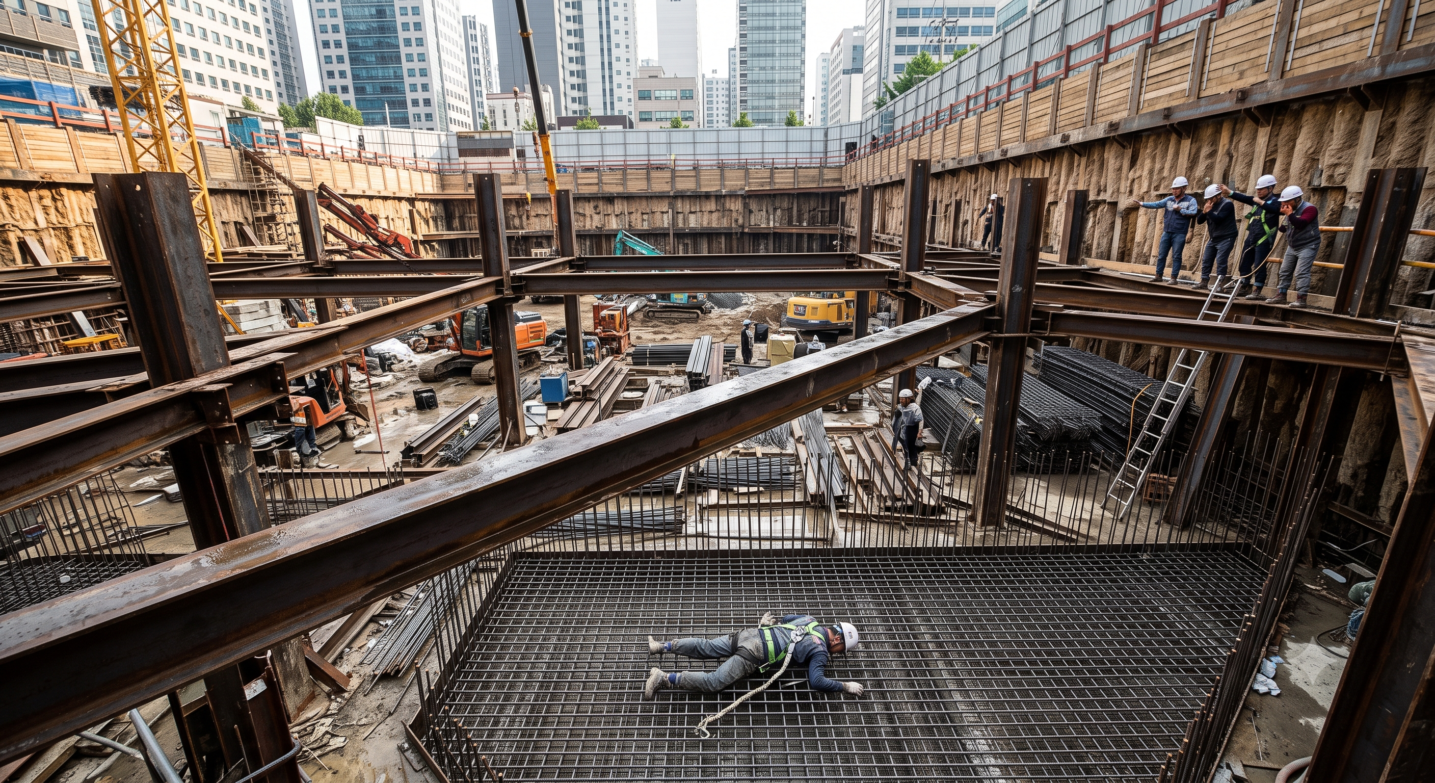
The illustration is a discussion aid. It does not establish equipment geometry, structural adequacy, the condition of a real site or an acceptable working method.
B. Initial conditions and developing hazard
In a fictional London basement project, a crew is installing a third level of steel struts approximately 12 metres above the excavation base. A newly positioned strut has only the temporary connections specified for an intermediate erection condition. Its completion inspection has not yet been carried out.
Overnight cooling has left dew on the upper flange. The morning briefing does not address the change in surface condition. A MEWP is available, but its position and reach for unhooking this particular member have not been confirmed.
To save time, an installer bypasses the planned access arrangement, disconnects the lanyard and steps onto the strut. The lifting team has no effective hold point preventing this access change.
C. Hypothetical event sequence
• The installer walks towards the lifting accessories on a narrow, wet flange.
• A foot slips and the installer loses balance. No guardrail or effective personal protection prevents a fall.
• The installer falls approximately 12 metres to the excavation base, with fatal injury as the assumed training outcome.
• Uncertainty about the member’s restraint and the remaining suspended load complicates the response and exposes would-be rescuers to additional hazards.
The stated height belongs only to this scenario. It is not a threshold below which fall protection is unnecessary.
D. Structural and mechanical interpretation
The fall can occur without any structural failure. Wet steel, narrow footing and the absence of effective fall prevention are sufficient mechanisms.
An incompletely restrained member may also roll, twist or translate under eccentric contact or an unintended erection load. Whether that occurs depends on its supports, connections, section properties and actual loading. Without drawings, calculations and physical evidence, member movement must remain a possible contributing mechanism rather than a proven cause.
In the completed support system, loads pass from the retained ground and groundwater through the retaining structure, walers, struts and designed reactions. Adequate axial capacity alone does not establish safety: end restraint, buckling length, eccentricity, bearing and connection behaviour also matter.
Hydraulic preloading introduces stored energy through pressurised fluid and elastic deformation of the support system. A slip or failure can convert that energy into rapid movement. It is inaccurate to describe the static preloaded condition as stored kinetic energy.
E. Failed protective barriers
| Protective barrier | Failure in the simulation | Required improvement |
|---|---|---|
| Access planning | The method does not demonstrate safe access to the actual unhooking position. | Confirm access and reach for each installation stage before lifting begins. |
| Weather and surface checks | Dew is present but does not trigger reassessment. | Review footing, access and equipment conditions when weather changes. |
| Collective fall prevention | The installer can enter an exposed route over the excavation. | Provide suitable protected access and control entry to incomplete steelwork. |
| Personal protection, where required | The lanyard is disconnected without an alternative protective arrangement. | Design the complete work and transfer method, including suitable anchorage and rescue. |
| Erection-stage control | The team does not distinguish temporary positioning from permission to access or load. | Use separate, clearly defined release conditions for crane support, access and loading. |
| Supervision and communication | A shortcut changes the agreed method without review. | Make stopping work and obtaining a revised safe method an explicit responsibility. |
| Emergency readiness | Structural and lifting hazards obstruct immediate response. | Plan rescue around the actual excavation, access equipment and incomplete structure. |
F. Key lesson
Providing a MEWP or issuing a harness does not, by itself, create a safe method. The task must be planned so that people can install, inspect and disconnect lifting accessories from protected positions, with the member stable for that exact erection stage.
5. Conditional decisions and common errors
| Condition | Action | Evidence | Proceed when |
|---|---|---|---|
| Rain or seepage changes | Hold the affected excavation; assess drainage and support response. | Water observations, movement trends and engineering disposition. | Water and support conditions accepted. |
| Rigging point unreachable | Stop unhooking; revise the protected access and lifting arrangement. | Access reach check, support assessment and lifting-team briefing. | Protected access and stable seating confirmed. |
| Unexpected preload response | Keep people clear; obtain the engineered response without uncontrolled unloading. | Force/movement log, equipment checks and revised load-transfer instruction. | Cause resolved; load retention accepted. |
| Next excavation stage | Close support defects and check monitoring before releasing the next cut. | As-built acceptance, stage drawing and current monitoring. | Required support accepted; monitoring active. |
A. Excavation stability and design assumptions
• Match the construction sequence to the geotechnical and structural design. Do not excavate below the authorised stage or remove restraint to improve access.
• Control plant, spoil, materials and traffic near the excavation according to the assessed surcharge and stability conditions. Do not adopt an arbitrary universal setback.
• Manage groundwater, surface water and dewatering effects on adjacent ground and structures. Pumping can change the conditions assumed in the design.
• Establish monitoring locations, baseline readings, trigger levels, reporting intervals and predefined responses before the relevant loading stage.
• Escalate unexpected soil, voids, water, cracking, settlement, wall movement, impact or support distortion. Keep people out of the affected area until it is assessed and made safe.
B. Lifting and crane release
The lifting plan must address the actual member, lifting points, centre of gravity, sling angles, edge protection, crane configuration and landing conditions. A double-choker hitch is not a universal legal requirement or a substitute for selecting a suitable lifting arrangement.
The load must not be released merely because a beam appears seated. Verify the bearing, connections and restraint required by the erection design, then carry out controlled load transfer under the lifting team’s direction. Welding is required only where the design specifies it.
Unless a competent person’s examination scheme specifies otherwise, LOLER thorough examination intervals are normally six months for equipment used to lift people and for lifting accessories, and twelve months for other lifting equipment. Additional examination circumstances must also be considered. Pre-use checks and maintenance do not replace thorough examination.
C. Access and fall prevention
Select suitable access after considering whether the work can be completed from a safe position without exposure to a fall. Guarded platforms, scaffolds and MEWPs are possible solutions; none is automatically suitable for every location.
• Do not use unprotected beam walking as the installation or unhooking method.
• For MEWPs, check reach, loading, ground support, overhead entrapment, operating limits and emergency recovery. Operators need appropriate training and familiarisation with the actual machine.
• Select restraint or fall-arrest arrangements for the equipment and task. Do not attach a lanyard to an unverified strut, handrail or improvised anchor.
• Where fall arrest is used, verify anchorage, clearance, compatibility and rescue. A harness does not prevent the initiating fall.
• Safety nets arrest falls; they do not perform the same function as guardrails. Personnel safety nets and debris nets are not interchangeable.
D. Connections, intersections and structural restraint
The designer must establish whether intersecting members require a connection and what that connection must achieve. Crossing beams do not automatically provide lateral restraint, and fitting an arbitrary U-bolt does not establish an effective brace.
Verify bolt assemblies, tightening requirements, weld details, stiffeners, bearing plates, packing and tolerances against the approved specification. Paint marks may help identify movement or completed checks but do not prove bolt preload or structural adequacy.
Do not add walkways, handrails, lifting points or service supports to shoring without confirming their loads and attachment details. Do not make site alterations to the steelwork without the required design approval.
E. Hydraulic preloading and energy control
PUWER does not establish one universal calibration interval for every hydraulic jack. Inspection and maintenance address equipment condition; measurement verification addresses the reliability of indicated force. Both must be suitable for the task.
• Confirm compatible jacks, pumps, hoses, couplings and gauges, including the lowest applicable component rating and the manufacturer’s permitted configuration.
• Establish the relationship between the indicated pressure and delivered force for the actual equipment. Gauge pressure alone cannot verify the support’s structural capacity.
• Verify jack alignment, seating, reaction strength, stroke allowance and the designed loading sequence. Do not introduce improvised packing or lateral loads.
• Keep people outside foreseeable ejection, hose-failure and member-movement paths. Use controls and monitoring positions specified in the planned method.
• Apply load in the approved stages and stop on unexpected displacement, pressure behaviour, leakage, noise, distortion or monitoring triggers.
• Complete the specified locking, retention or transfer arrangement before altering hydraulic support. A purpose-designed hydraulic prop may retain pressure as part of its intended operation; a temporary jack may require a different transfer arrangement.
• A zero gauge reading does not prove that a strut is unloaded. Do not loosen connections or dismantle equipment without the approved unloading procedure.
A hydraulic system is not automatically subject to LOLER solely because it uses hydraulic pressure. Assess its actual function: lifting or lowering loads can bring LOLER into scope, while pushing or preloading still requires suitable equipment controls.
F. Welding, fire and atmospheric hazards
Assess welding fume under COSHH. Consider reducing site welding through design-approved alternatives. Where welding remains necessary, provide effective source capture where practicable and suitable respiratory protection where extraction cannot adequately control exposure. HSE specifies suitable RPE for outdoor welding; also protect nearby workers.
Assess the actual excavation’s ventilation. An open top does not demonstrate adequate air movement at the work position. Particulate filters do not protect against oxygen deficiency or every welding gas. Tight-fitting RPE requires appropriate face-fit testing and use.
Implement the project’s hot-work controls, including combustible-material checks, suitable screens, cylinder and hose management, firefighting equipment and fire-watch arrangements where assessed as necessary. Set any post-work monitoring period through the permit assessment rather than inventing a universal duration.
Where the location meets the confined-space definition, apply the relevant entry, atmospheric control and rescue requirements before entry. Do not rely on unplanned rescue by colleagues.
G. Weather and conflicting limits
Record the relevant limits for lifting, MEWP operation, access, welding and hydraulic equipment. Use the most restrictive applicable requirement where the limits concern the same operating condition. Do not directly compare limits that relate to different activities or equipment configurations. A permit cannot authorise operation beyond a manufacturer’s limit.
6. Roles and responsibilities
| Role | Responsibilities for this activity |
|---|---|
| Client and principal designer, where applicable | Ensure relevant project arrangements and information support safe design and construction; coordinate design risks within their respective CDM duties. |
| Principal contractor or contractor controlling the work | Coordinate the construction method, interfaces, resources, access, supervision and implementation of the construction phase plan. |
| TWC or equivalent appointed coordinator | Maintain the temporary works process, coordinate design and site information, track inspections and hold points, and issue or arrange releases within the authority formally assigned. |
| Temporary works designer | Define the support arrangement, erection and loading assumptions, restraints, preload requirements, monitoring criteria and acceptable changes. |
| Design checker | Perform the specified design check within the agreed scope and competence requirements; record findings and unresolved matters. |
| Site supervisor or temporary works supervisor | Check that installation follows the current method and drawings, maintain records, brief the workforce and stop work when conditions depart from the plan. |
| Person planning the lift and lifting supervisor | Establish and implement the lift plan, lifting equipment configuration, responsibilities, communications and load-transfer arrangements. |
| Crane operator and slinger/signaller | Perform the agreed lifting operation within their competence and authorisation; verify signals, rigging and safe load handling. |
| MEWP operator and rescue personnel | Operate the appropriate equipment following training and model familiarisation; maintain the planned recovery and rescue capability. |
| Competent excavation inspector | Inspect at the required times, identify unsafe conditions and communicate findings and reporting requirements. |
| Installers, welders and hydraulic operators | Follow the approved method, use suitable equipment, maintain exclusions and report defects or unexpected behaviour. |
| Safety adviser | Support assessment, briefing and verification without assuming structural design or release authority unless separately competent and appointed. |
A. Competence and authority
Training, an industry card, professional registration, fitness for a task and employer authorisation are different matters. No single card establishes competence for all lifting, access, welding or temporary works activities.
A designer does not automatically become the TWC, and a TWC does not automatically have authority to redesign a connection or change preload values. Record appointments, delegation and limits of authority.
Supervision, records, handover
| Job stage | Technical and procedural controls | Site verification |
|---|---|---|
| Plan ownership | 1. Verify assigned authority2. Check staged design3. Set monitoring triggers | 1. Design and stage revision2. Ground and water record3. Service clearance |
| Team and equipment | 1. Record equipment evidence2. Verify actual lift setup3. Exclude load movement zone | 1. Mass and rigging check2. Plant support assessment3. Access and rescue plan |
| Stage release | 1. Hold stage release2. Fit designed restraints3. Verify member and seating | 1. Member identification2. Restraint inspection3. Protected access check |
| Energy control | 1. Record energy controls2. Use engineered procedure3. Verify retained load transfer | 1. Jack and gauge records2. Preload and movement log3. Lock-off acceptance |
| Inspection closure | 1. Close inspection defects2. Close stage defects3. Record acceptance evidence | 1. As-built support record2. Walkway and guard check3. Added-load approval basis |
| Shift handover | 1. Transmit limits and issues2. Release next stage explicitly3. Use planned protected rescue | 1. Stage and limits handover2. Monitoring status3. Change-control record |
7. Hold points and record comparison
A. Release principles
The following hold points are proposed project controls. Their titles are not presented as universally prescribed statutory permit names. Assign a responsible person, acceptance evidence, validity conditions and a signed release for each applicable stage.
| Hold point | Release conditions | Required evidence and authority |
|---|---|---|
| HP1 — Design and method release | Design and required checks complete; sequence, equipment interfaces and site assumptions resolved. | Current drawings, check records and RAMS; release through the appointed temporary works procedure. |
| HP2 — Excavation and working area ready | Required excavation inspection completed; ground, water, plant support and exclusions acceptable. | Inspection findings, resolved actions and working-platform information; competent inspector and controlling supervisor input. |
| HP3 — Lift and protected access ready | Lift arrangement and access to installation and unhooking points established; rescue provisions available. | Lift plan, equipment status, briefing and access checks; responsible lifting and site personnel. |
| HP4 — Individual member crane release | Required seating, connections and erection restraint installed and checked; safe controlled transfer possible. | Member-specific verification by the appointed competent person and coordinated release by the lifting team. |
| HP5 — Preloading authorised | Design prerequisites, reaction points, hydraulic equipment, monitoring and exclusion arrangements verified. | Preloading procedure, equipment records and installation checks; authorised release with designer input where specified. |
| HP6 — Preload and load transfer accepted | Required preload response and movements accepted; retention or transfer arrangement complete; defects resolved. | Signed preload record, monitoring results and connection checks; acceptance within the project’s assigned authority. |
| HP7 — Next excavation stage authorised | Installed support accepted; loading restrictions and next excavation limits clear. | Completion inspection and applicable permit to load or proceed; authorised temporary works release. |
| HP8 — Restart after change or abnormal event | Incident, weather effect, movement, damage or design change assessed; necessary inspections and revisions complete. | Updated assessment, design instructions and rebriefing; new authorisation by the relevant responsible persons. |
B. Suspension and revalidation
Suspend affected permits when their assumptions cease to hold. Examples include plant relocation, loss of monitoring, altered supports, unexpected groundwater, damaged equipment or changed access. Restart only after the necessary review and release.
Hot-work and confined-space permits, where required by the safe system, remain separate controls with their own limits and close-out requirements.
Record comparison examples
The scenario and record comparisons are fictional teaching examples, not records of real incidents, measurements, inspections, signatures or approvals.
The boxes are static record prompts, not interactive or saved approvals. A tick does not establish suitability or permission to restart. Record the evidence, person, time and unresolved issues; retain the change history.
| Record type | Insufficient record | Record checklist |
|---|---|---|
| Plan and ground | “OK” | □ Design and stage revision□ Ground and water record□ Service clearance□ Baseline and triggers |
| Place struts | “OK” | □ Member identification□ Restraint inspection□ Protected access check□ Load-transfer release |
| Preload and lock | “OK” | □ Jack and gauge records□ Preload and movement log□ Lock-off acceptance□ Leak and pressure checks |
| Handover and monitor | “OK” | □ Stage and limits handover□ Monitoring status□ Change-control record□ Emergency readiness |
8. Site checklist and emergency response
A. Design and excavation
• Confirm the correct design revision, member schedule, excavation stage and installation method.
• Verify that the required excavation inspection is complete and unsafe findings have been resolved.
• Check ground conditions, groundwater, services, adjacent structures and permitted surcharge.
• Confirm plant positions and working-platform conditions against the assessed arrangement.
B. Lifting, access and equipment
• Confirm the crane configuration, lift plan, lifting accessories and competent lifting team.
• Check relevant examination reports, inspections and outstanding equipment defects.
• Confirm safe access to every connection and unhooking position.
• Check MEWP suitability, familiarisation, emergency controls and rescue readiness where a MEWP is used.
• Verify edge protection, controlled access and protection against falling objects.
C. Steelwork and preloading
• Check member identity, condition, orientation, bearing surfaces and required temporary restraint.
• Confirm the specified bolt assemblies, weld requirements and inspection arrangements.
• Verify jack and pump compatibility, hose condition, ratings and force-measurement evidence.
• Confirm preload targets, sequence, monitoring baselines and stop criteria from the approved documents.
• Identify the authorised load-transfer arrangement and prohibit unplanned release of hydraulic support.
D. Work environment and authorisation
• Review wet surfaces, visibility, wind and other relevant operating conditions.
• Confirm welding-fume, fire and atmospheric controls for the actual work location.
• Verify permit boundaries, simultaneous operations, communications and emergency access.
• Confirm named hold-point authorities and the team’s understanding of stop-work triggers.
Record the person completing the checks, date, work area, drawing revision, defects and corrective actions. A ticked checklist does not replace statutory inspections or technical acceptance.
9. Sources and review limits
Review update, 12 October 2026: the entries below identify the official material rechecked for this revision and its specific scope. Earlier source notes and dates are retained as revision history; they do not mean that every cited provision was reverified today. Full paid standards, actual equipment manuals, site calculations and approvals were not supplied or verified. Resolve their current applicability with a qualified reviewer before use.
| Source | Scope and limitations |
|---|---|
| HSE — Temporary works | Public guidance covers planning, foreseeable loads, competent design and checking, correct erection and inspection. A temporary-works coordinator is an effective management arrangement; the title is not itself a universal statutory appointment. |
| HSE — Excavations | Plan support before excavation and inspect at the required times and after relevant events. No ground is universally safe to stand unsupported. Full BS 5975 text was not reviewed. |
A. Legislation and official guidance
The following sources support the legal framework and control principles used in this guide:
| Official source | Relevant application |
|---|---|
| HSE — Managing health and safety in construction, L153 | CDM 2015 regulation text and guidance, including structural stability, excavation inspections and reporting. |
| HSE — Excavations | Collapse prevention, water, adjacent loads and inspection arrangements. |
| Legislation.gov.uk — Work at Height Regulations 2005, original instrument | Original statutory text; subsequent amendments must be checked before use. |
| HSE — Assessing all work at height | Application of the work-at-height hierarchy. |
| HSE — Safe use of lifting equipment, L113 | LOLER regulation text, Approved Code of Practice and guidance. |
| HSE — Thorough examination and inspection of lifting equipment | Examination schemes, intervals and other examination circumstances. |
| HSE — Safe use of work equipment, L22 | PUWER suitability, maintenance, inspection and competence provisions. |
| HSE — Mobile elevating work platforms | MEWP selection, ground conditions, fall protection, training and rescue. |
| HSE — Controlling the risks from welding | Welding-fume control, extraction, respiratory protection and protection of others. |
| HSE — Safe work in confined spaces, L101 | Confined-space assessment, safe systems, permits and emergency arrangements. |
| HSE — Construction administration | Risk assessments, method statements and construction phase planning. |
| HSE — Temporary works FAQs | Temporary works coordination and the distinction between legal duties and particular management titles. |
B. Technical standards
• BSI — BS 5975-1:2024: Management procedures for the control of temporary works.
• BSI — BS 5975-2:2024: Falsework — Design and implementation.
The BSI public records were checked for titles, publication, status and published scope. The paid standards were not read in full; this guide does not claim clause-by-clause verification or certification of conformity.
C. Applying the sources
Applicable legislation must be satisfied. Approved Codes of Practice have a distinct legal status; ordinary guidance and British Standards are not automatically legislation. Project contracts and specifications may nevertheless require particular standards and procedures.
The approved design, equipment instructions and site arrangements must be compatible with those duties. Resolve any conflict through the responsible designer, equipment supplier and project authority before work. Do not select whichever requirement is easiest to meet.
D. Dates, amendments and verification limits
CDM 2015 came into force on 6 April 2015; the original Work at Height Regulations 2005 came into force on 6 April 2005. These commencement dates are different from the dates of later guidance updates.
Publication of the two BS 5975 parts on 31 December 2024 is a standards event, not a statutory commencement date. No universal legal transition period has been assumed. Check the project’s specified editions and change-control arrangements.
Official regulation texts in HSE publications and the original work-at-height instrument were reviewed alongside current HSE web guidance. Access to the live consolidated legislation pages was not available for every instrument. Accordingly, this is not an exhaustive verification of all amendments, commencement provisions or transitional arrangements current at the date below. The responsible reviewer must confirm the legislation in force before site adoption.
E. Inspection and recording distinction
For supported or battered excavations within CDM regulation 22(4), inspection is required at the start of the working shift and after the specified stability-affecting events or unintended falls or dislodgements of material. A weekly reporting provision does not reduce this inspection frequency. Apply regulation 24’s reporting and retention requirements where triggered, and maintain the project’s inspection records.
10. PDF guidance and FAQ
PDF A covers basic task controls; B focuses on technical failures; C covers supervision, records and handover. The article has eight stages with four items per main cell; each PDF has six key stages with three items per main cell. P/S/R/A, measurements, confirmations and signatures remain blank for actual site assessment.
The three PDF sheets are complementary extracts, not a complete work sequence. Apply all eight body stages and the applicable site procedure. PDF HP-0 to HP-4 are worksheet labels: match each to its event, evidence and responsible authority, not to the same number in a different permit or table. An omitted PDF stage is not permission to omit its controls.
A. Proposed document inputs
The following fields are proposed for a structured documentation workflow. They are not a statement that every listed function currently exists in Smart JSA Bridge.
| Field group | Information to capture |
|---|---|
| Project and jurisdiction | Project name, Great Britain jurisdiction, work location, en-GB language and document revision. |
| Temporary works identification | Register reference, support level, member identifiers, designer, checker and coordination appointments. |
| Design references | Drawing and calculation revisions, design-check status, erection sequence and relevant specifications. |
| Site conditions | Groundwater, ground conditions, adjacent assets, services, surcharge and plant positions. |
| Lifting and access | Lift-plan reference, crane configuration, accessories, access method and rescue arrangements. |
| Connections and restraint | Bearing details, specified fixings, inspection records and crane-release prerequisites. |
| Hydraulic preloading | Equipment identification, approved target values, measurement basis, sequence and load-transfer arrangement. |
| Monitoring | Baseline readings, trigger values, inspection frequency, responsible persons and escalation actions. |
| Permits and hold points | Scope, issuer, release authority, evidence, validity conditions, suspension and close-out status. |
| Risk assessment | Site-defined P, S, R and A entries with assessor identity and justification. |
| Review and change control | Review scope, unresolved issues, signatures, approved revisions and rebriefing records. |
B. Proposed workflow checks
• Flag missing design revisions, incomplete hold points and unresolved defects for human review.
• Identify overdue inspection or examination records using the applicable recorded requirements.
• Require review when equipment, geometry, groundwater, loading or the excavation sequence changes.
• Keep design values traceable to the authorised source rather than generating them from generic defaults.
• Retain evidence of who entered, checked and approved each critical item.
These are proposed review rules, not verified automatic interlocks. A software flag cannot physically stop a lift, maintain excavation stability or grant statutory approval.
C. Documentation use
Smart JSA Bridge may be used as part of a document-preparation workflow, subject to confirming its actual available functions. Output must be checked against the project’s design, equipment and site conditions. No claim of automatic HSE compliance, engineering certification or guaranteed safe operation is made.
Is a JSA or RAMS document sufficient to authorise H-beam shoring installation?
No. A JSA or RAMS document supports task planning but does not replace the temporary works design, construction phase plan, lifting plan, equipment examinations, excavation inspections or project authorisations. Installation and further excavation must follow the approved sequence and applicable hold points.
Does UK law require the job title Temporary Works Coordinator?
HSE states that there is no legal requirement to use that particular job title or the BS 5975 process. Temporary works must nevertheless be properly managed. BS 5975-1:2024 provides a recognised management framework, and a project's contract or procedures may require a formally appointed Temporary Works Coordinator.
When can the crane be released from an installed waler or strut?
The crane may be released only after the member has the bearing, connections and temporary restraint required for that erection stage, the responsible person has verified those conditions, and the lifting team has confirmed controlled load transfer. Welding is not universally required because the approved design may use bolted, proprietary or other engineered connections.
Does reaching the specified hydraulic pressure prove that shoring is safe?
No. Hydraulic pressure is one measurement within a designed preloading procedure. Acceptance also depends on the equipment's pressure-to-force relationship, alignment, bearing, connections, restraint, movement readings and the approved load-transfer arrangement. A pressure gauge alone cannot demonstrate structural adequacy.
Must every H-beam installation task use a MEWP?
No. Access must be selected through the work-at-height hierarchy and the task assessment. Suitable guarded platforms, scaffolds or MEWPs may be appropriate. Unprotected beam walking is not an acceptable access method. Any personal fall-protection system needs suitable anchorage, compatible equipment and a workable rescue arrangement.
Has a professional verified or approved this document?
No. Public sources and editorial, layout and consistency checks were reviewed using AI. No site inspection or professional technical approval has been performed. Obtain appropriate professional review before use.
11. Revision history and authorship
A. Document status
This document is a technical draft generated through the Smart JSA Bridge automated engineering-content workflow. It is intended to support preparation of project-specific JSA/RAMS and work-permit arrangements.
B. No verified professional or regulatory approval
Unless supported by an independently verifiable signature and review record, this document must not be represented as authored, reviewed or approved by a practising engineer, safety professional, equipment manufacturer or government authority.
C. No physical inspection
The system has not physically inspected the excavation, ground, supports, lifting equipment, hydraulic equipment, access arrangements or actual working conditions. It cannot confirm installed dimensions, connection quality, equipment condition or compliance on site.
D. Documents and duties not replaced
This draft does not replace legal advice, manufacturer instructions, structural or geotechnical calculations, statutory inspection or examination reports, competence evidence, site risk assessment or work authorisation. The fictional incident and its structural discussion are not an accident investigation or a design calculation.
E. Required review before use
Before site use, appropriately competent and authorised persons must review the content for the jurisdiction, project, support design and actual equipment. Resolve missing information, technical conflicts and outstanding hold points before authorising the affected work. Approval must identify its scope, conditions and limits.
F. Actual professional review record
Any review actually performed must be recorded separately with:
• Reviewer’s name and organisation.
• Relevant qualifications, competence and formal delegation of authority.
• Scope of the review.
• Equipment, drawings, calculations, manuals and other documents reviewed.
• Review date and signature.
• Limitations and exclusions.
• Required amendments and evidence of their resolution.
• Conditions under which approval remains valid, including changes requiring renewed review.
Legislation, guidance and source-check date: 19 September 2026, subject to the verification limits in Section 9. Recheck current legislation, applicable standard editions, manufacturer instructions and site conditions before use.
2026-10-12 · v2026.10.12
Revision: the master JSA is organised into eight stages with four prompts in each main cell. Short conditional release criteria and sixteen record prompts separate evidence from approval. Three six-stage PDFs use task, technical-failure and supervision viewpoints; actual evaluation fields remain blank. Valid prior explanations, sources and history are retained. This is an editorial revision, not professional technical verification.
This is reference content written and revised with AI. It has not been verified or approved by a professional. Review by a suitably qualified professional and site authorisation are required before use.