This revision retains route checks, machine inspection, overhead positioning, installation, descent and charging. It separates load planning and fault response, and replaces universal sensor, harness and travel claims with decisions tied to the actual machine and jurisdiction.
Keep the operator clear of overhead traps and preserve a workable ground rescue route
This is reference content written and revised with AI. It has not been verified or approved by a professional. Review by a suitably qualified professional and site authorisation are required before use.
Stop work
Stop for lost clearance, unexpected motion, damaged guardrails, any bypassed or faulty safety function, unknown floor capacity, load-limit breach, uncontrolled people below, electrical uncertainty or loss of rescue capability. Keep the machine out of service until the cause is addressed.
1. Legal and technical scope
| Basis | Application limits |
|---|---|
| HSE · MEWPs | Official operational guidance, including rescue practice, controls, competence and examination; accessed 12 October 2026. |
| HSE · Entrapment bulletin | 2010 bulletin: equipment selection, planning, model-specific instruction and practised rescue. Historical technical alert, not a current product certificate. |
Great Britain: HSE MEWP guidance explains planning, competence, ground conditions, rescue and examination in the work-equipment framework. This article is not a statutory examination report. Northern Ireland requirements need separate confirmation; paid BS/EN texts were not read.
A training card is evidence to assess, not the employer’s entire competence or site-familiarisation decision. HSE describes six-month examination for lifting people or an examination scheme; pre-use checks are separate. Restraint selection depends on remaining fall risk and suitable manufacturer anchor, rather than a blanket rule for every scissor lift.
2. Scope and required inputs
Included scope
Planned installation of supported building-service components from a scissor platform on a verified floor: route selection, pre-use tests, loading, positioning, fixing, fault response, relocation and secure parking.
Separate review
Lifting suspended loads as a crane, pushing or pulling structures with the platform, leaving an elevated platform, live electrical work and maintenance under an unsupported scissor stack require separate engineered methods. They are not authorised by this example.
| Required input | What to verify |
|---|---|
| Plan route | Slab assessment · Route survey · Traffic plan · Supply identification |
| Inspect lift | Model and serial · Test results · Repair release · Rescue operator |
| Board and load | Load calculation · Carrier approval · Load distribution · Access condition |
| Raise platform | Overhead route · Electrical controls · Wind and slope limits · Guard function |
| Park and charge | Parking condition · Defect handover · Charger compatibility · Battery condition |
Use the exact model, serial range and manual to establish load, extension-deck, wind, side-force, slope and elevated-travel limits. No universal wind speed, floor step, anchor strength, hydraulic force or injury threshold is supplied. A tilt alarm is a warning, not a levelling instrument.
Select head, eye, hand, foot, hearing and respiratory protection for drilling and handling exposures. Guardrails and a closed gate remain essential. Additional restraint or fall protection must meet applicable rules and the manufacturer’s compatible anchor/system instructions; never attach to a handrail or improvise an anchor.
3. Eight-stage JSA
| Job stage | Hazards and effects | Failure factors | Technical and procedural controls | Site verification | P | S | R | A |
|---|---|---|---|---|---|---|---|---|
| 1. Plan route | 1. Wheel drop2. Slab failure3. Pedestrian strike4. Cable contact | 1. Unrated cover2. Hidden void3. Mixed traffic4. Unidentified supply | 1. Verify wheel loads2. Secure rated covers3. Separate pedestrians4. Arrange electrical controls | 1. Slab assessment2. Route survey3. Traffic plan4. Supply identification | ||||
| 2. Inspect lift | 1. Unwanted motion2. Failed lowering3. Hydraulic leak4. Fall at gate | 1. Bypassed interlock2. Damaged hose3. Worn brake4. Open gate | 1. Test per manual2. Quarantine defects3. Check ground controls4. Close entry gate | 1. Model and serial2. Test results3. Repair release4. Rescue operator | ||||
| 3. Board and load | 1. Overload2. Falling material3. Trip on deck4. Overexertion | 1. Extension overloaded2. Load on rail3. Loose cords4. Awkward component | 1. Count people and tools2. Check extension limit3. Use approved carrier4. Keep deck clear | 1. Load calculation2. Carrier approval3. Load distribution4. Access condition | ||||
| 4. Raise platform | 1. Overhead crushing2. Electrical contact3. Tip-over4. Trapped controls | 1. Blind clearance2. Live service3. Excess side force4. Defeated guard | 1. Survey full travel envelope2. Keep body off controls3. Follow model limits4. Stop on lost clearance | 1. Overhead route2. Electrical controls3. Wind and slope limits4. Guard function | ||||
| 5. Install services | 1. Fall from rail2. Dropped drill3. Crush by component4. Dust exposure | 1. Improvised step2. Unsecured tool3. Unsupported load4. Hidden service | 1. Keep feet on deck2. Tether suitable tools3. Independently support load4. Control drilling dust | 1. Safe reach2. Exclusion zone3. Fixing design4. Service isolation | ||||
| 6. Respond to fault | 1. Continued crushing2. Uncontrolled descent3. Delayed rescue4. Electrical injury | 1. Repeated reset2. Unknown controls3. Blocked ground access4. Damaged circuit | 1. Stop and alert2. Apply rehearsed rescue3. Use trained ground person4. Isolate after rescue | 1. Fault location2. Safe release direction3. Rescue access4. Repair evidence | ||||
| 7. Lower and move | 1. Scissor pinch2. Collision3. Overturn on ramp4. Snagged cable | 1. Person in mechanism2. Blind rear path3. Raised travel misuse4. Trailing supply | 1. Clear descent zone2. Lower before relocation3. Follow permitted travel mode4. Secure trailing lines | 1. Ground clearance2. Gate closed3. Route recheck4. Signal agreement | ||||
| 8. Park and charge | 1. Roll-away2. Unauthorised use3. Battery fire4. Electric shock | 1. Incorrect parking2. Key left in place3. Wrong charger4. Damaged cable | 1. Park per manual2. Secure key and controls3. Match battery and charger4. Ventilate as specified | 1. Parking condition2. Defect handover3. Charger compatibility4. Battery condition |
PDF A covers basic task controls; B focuses on technical failures; C covers supervision, records and handover. The article has eight stages with four items per main cell; each PDF has six key stages with three items per main cell. P/S/R/A, measurements, confirmations and signatures remain blank for actual site assessment.
4. Fictional scenario and failure mechanisms
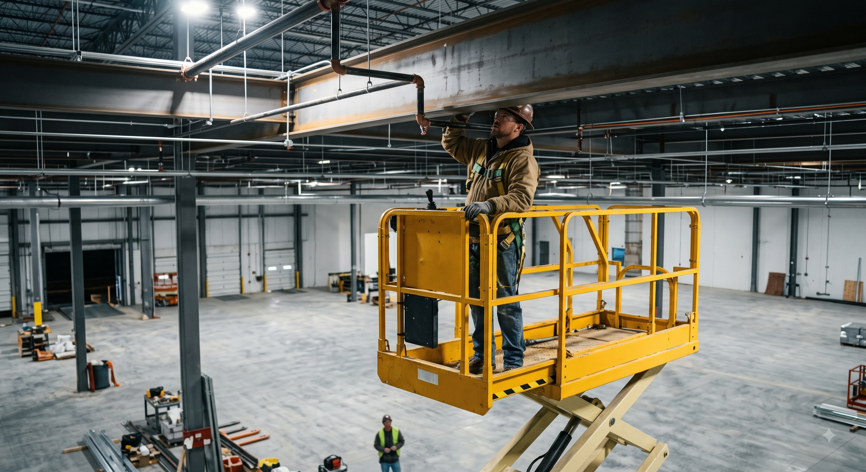
Retained educational illustration; not evidence of an actual incident or site suitability. Its creation method, including possible AI use, has not been verified.
The scenario and record comparisons are fictional teaching examples, not records of real incidents, measurements, inspections, signatures or approvals.
| Item | Fictional scenario |
|---|---|
| Initial situation | A crew plans to fix a cable tray below a beam using a scissor lift. |
| Changed condition | The full clearance envelope is obscured and a fitted protective device repeatedly stops motion. |
| Failure path | Resetting or bypassing that device while leaning over the controller could keep the operator in the crushing path. |
| Possible outcome | Entrapment or a delayed rescue is a possible outcome; no actual accident, investigation or measured force is asserted. |
| Prevention barrier | Stop, lower only in a safe release direction, revise the position or access method and test the rescue arrangements before a new decision. |
Failure mechanisms
As platform height rises, side forces and uneven wheel support can reduce stability. The slab must carry wheel reactions, not merely the total machine weight spread over its footprint. Cover stiffness, voids, extension loads and local edges matter. A small-step or moment formula alone cannot establish a safe route.
Entrapment can force a person onto controls. Protected controls and any compatible secondary protection reduce particular risks but do not sense every obstacle or guarantee reversal. Inspect the fitted system as the manual specifies; repeated triggering requires reassessment, never a bypass.
Count people, tools, materials and approved attachments in the payload, including the extension-deck limit. Do not load rails or use the platform to force a component into place. Support components independently, locate hidden services before drilling, control dust and prevent dropped objects without creating tether snag hazards.
Battery controls depend on chemistry and charger instructions: gas and acid hazards may apply to lead-acid batteries, while damaged lithium batteries need their own isolation and fire response. Match the charger, inspect cables and use the designated charging arrangement; do not generalise hydrogen production to every battery.
Decision sequence
| Decision stage | What to verify |
|---|---|
| Known facts | Known: the protective device has triggered near the overhead beam. |
| Unresolved matters | Unknown: the full movement envelope, fault condition and safest release direction. |
| Reason to hold | Hold: further elevation could trap the operator or worsen an existing pinch. |
| Required evidence | Obtain: model instructions, clearance survey, competent defect assessment and a demonstrated ground rescue procedure. |
| Restart decision | Restart only after the cause is addressed, the route and protection are reassessed and the authorised site decision is recorded. |
5. Conditional decisions and common errors
| Condition | Action | Evidence | Proceed when |
|---|---|---|---|
| Unknown floor cover | Hold outside the cover. | Wheel-load and cover assessment. | Load path verified |
| Repeated guard trip | Stop; investigate the cause. | Clearance survey and function test. | Cause resolved |
| Load exceeds limit | Unload or change method. | Payload and extension calculation. | All limits met |
| Changed travel route | Lower; resurvey the route. | Surface, people and overhead check. | Route clear |
| Battery damage | Stop charging; isolate safely. | Battery-specific competent advice. | Released battery system |
Similar situations, different decisions
The scenario and record comparisons are fictional teaching examples, not records of real incidents, measurements, inspections, signatures or approvals.
| Comparison | Situation A | Situation B |
|---|---|---|
| Alarm reset | Alarm stops after a reset; the cause is unknown, so remain on hold. | Cause is resolved and function is checked; record the new operating decision. |
| Travel | A lowered platform still needs a safe route and clearance. | Raised travel additionally needs explicit model permission and all operating limits. |
| Rescue | Knowing the valve location does not show that its use is safe. | A trained person understands release direction and can reach the correct controls. |
6. Roles and responsibilities
| Role | Responsibility |
|---|---|
| Route release | Assign route assessor · Check wheel-load evidence · Coordinate other trades |
| Accept machine | Check competence · Review defect log · Assign ground rescuer |
| Approve loading | Review total payload · Confirm carrier approval · Allocate material handler |
| Direct overhead work | Brief entrapment envelope · Agree stop signal · Control access below |
| Manage abnormal stop | Keep machine on hold · Coordinate safe rescue · Require repair evidence |
| Hand over and secure | Transfer outstanding defects · Control key custody · Confirm charging arrangements |
Supervision, records, handover
| Job stage | Technical and procedural controls | Site verification |
|---|---|---|
| Route release | 1. Assign route assessor2. Check wheel-load evidence3. Coordinate other trades | 1. Assessor name2. Cover rating3. Pedestrian separation |
| Accept machine | 1. Check competence2. Review defect log3. Assign ground rescuer | 1. Operator authorisation2. Model familiarisation3. Rescue demonstration |
| Approve loading | 1. Review total payload2. Confirm carrier approval3. Allocate material handler | 1. Payload worksheet2. Extension limit3. Handling plan |
| Direct overhead work | 1. Brief entrapment envelope2. Agree stop signal3. Control access below | 1. Briefing record2. Signal agreement3. Exclusion owner |
| Manage abnormal stop | 1. Keep machine on hold2. Coordinate safe rescue3. Require repair evidence | 1. Incident location2. Rescue control direction3. Restart decision |
| Hand over and secure | 1. Transfer outstanding defects2. Control key custody3. Confirm charging arrangements | 1. Handover owner2. Open defect list3. Charger and battery ID |
7. Hold points and record comparison
| Hold point | Evidence before release | Confirmation / approval |
|---|---|---|
| Start | Planned installation of supported building-service components from a scissor platform on a verified floor: route selection, pre-use tests, loading, positioning, fixing, fault response, relocation and secure parking. | |
| HP-1 Inspect lift | Model and serial · Test results · Repair release · Rescue operator | |
| HP-2 Board and load | Load calculation · Carrier approval · Load distribution · Access condition | |
| HP-3 Raise platform | Overhead route · Electrical controls · Wind and slope limits · Guard function | |
| HP-4 Respond to fault | Fault location · Safe release direction · Rescue access · Repair evidence |
Complete after actual checks. Recheck after changes, defects or shift handover.
Record comparison examples
The scenario and record comparisons are fictional teaching examples, not records of real incidents, measurements, inspections, signatures or approvals.
The boxes are static record prompts, not interactive or saved approvals. A tick does not establish suitability or permission to restart. Record the evidence, person, time and unresolved issues; retain the change history.
| Record type | Insufficient record | Record checklist |
|---|---|---|
| Route | Route safe. | □ Slab assessment□ Route survey□ Traffic plan□ Supply identification |
| Inspection | Machine checked. | □ Model and serial□ Test results□ Repair release□ Rescue operator |
| Elevation | Space clear. | □ Overhead route□ Electrical controls□ Wind and slope limits□ Guard function |
| Handover | Lift ready. | □ Parking condition□ Defect handover□ Charger compatibility□ Battery condition |
8. Site checklist and emergency response
| Check item | Result | Person / action |
|---|---|---|
| □ Plan route: Slab assessment | ||
| □ Inspect lift: Model and serial | ||
| □ Board and load: Load calculation | ||
| □ Raise platform: Overhead route | ||
| □ Install services: Safe reach | ||
| □ Respond to fault: Fault location | ||
| □ Lower and move: Ground clearance | ||
| □ Park and charge: Parking condition | ||
| □ Release / handover authority |
Stop work
Stop for lost clearance, unexpected motion, damaged guardrails, any bypassed or faulty safety function, unknown floor capacity, load-limit breach, uncontrolled people below, electrical uncertainty or loss of rescue capability. Keep the machine out of service until the cause is addressed.
Emergency response
Stop motion and raise the alarm. Keep others away and use the practised model-specific rescue plan. A trained ground person must choose a release movement that does not increase crushing; blindly lowering can worsen entrapment. If electrical contact is suspected, prevent approach until the supply authority or competent electrical team makes it safe. After rescue, isolate the lift and preserve the defect record; do not reset and resume.
9. Sources and review limits
2026-10-12
| Source | Scope and limitations |
|---|---|
| HSE · MEWPs | Official operational guidance, including rescue practice, controls, competence and examination; accessed 12 October 2026. |
| HSE · Entrapment bulletin | 2010 bulletin: equipment selection, planning, model-specific instruction and practised rescue. Historical technical alert, not a current product certificate. |
This is reference content written and revised with AI. It has not been verified or approved by a professional. Review by a suitably qualified professional and site authorisation are required before use.
10. PDF guidance and FAQ
PDF A covers basic task controls; B focuses on technical failures; C covers supervision, records and handover. The article has eight stages with four items per main cell; each PDF has six key stages with three items per main cell. P/S/R/A, measurements, confirmations and signatures remain blank for actual site assessment.
Content group ID
jsa-scissor-lift
Does every lift have an anti-crush bar?
No. Select suitable equipment and verify the actual fitted protection and its limitations. A device does not replace clearance planning.
May the lift travel while elevated?
Only where the exact machine instructions and site assessment permit it. Lower before ordinary relocation; do not infer permission from the presence of a drive joystick.
Is a harness always required?
The decision depends on jurisdiction, machine and assessment. Keep guardrails effective and use only compatible approved anchor arrangements if personal protection is required.
What makes rescue ready?
An accessible ground-control route, a trained person, reliable communication and a practised procedure that considers the direction of release.
Has a professional verified or approved this document?
No. Public sources and editorial, layout and consistency checks were reviewed using AI. No site inspection or professional technical approval has been performed. Obtain appropriate professional review before use.
11. Revision history and authorship
This is reference content written and revised with AI. It has not been verified or approved by a professional. Review by a suitably qualified professional and site authorisation are required before use.
| Date | Version | Change | Review status |
|---|---|---|---|
| 2026-08-18 | Original version unmarked | Original preserved | No professional approval |
| 2026-10-12 | 1.1 | Decisions, records, JSA and PDFs revised | No professional approval |
Retained the original six work themes and image. Removed invented regulator investigation results, numerical injury claims and automatic professional/compliance guarantees. The eight-stage revision distinguishes machine-specific protection, movement and fall-control requirements, electrical isolation, support of materials and battery chemistry. Actual assessments and approvals are blank.