Rebar work changes the load path several times: a restrained delivery bundle becomes loose stock, a crane-supported cage becomes a temporarily braced structure, and a completed cage is handed to another trade. Each transfer needs a defined hold point. This revision preserves the original receiving, fabrication, lifting, access, assembly and housekeeping controls while separating planning and final inspection.
Verify temporary stability before releasing the hook
This is reference content written and revised with AI. It has not been verified or approved by a professional. Review by a suitably qualified professional and site authorisation are required before use.
Stop work
Stop for an unverified lifting point, unknown load or deck capacity, ineffective guard, lost signals, missing brace, damaged end protection or weather outside the design limits. Keep people out and resolve the cause before a fresh release.
1. Legal and technical scope
| Basis | Application limits |
|---|---|
| HSE: Temporary works | Reviewed public guidance on temporary-works planning and responsibility; no site design verified. |
| HSE: PUWER overview | Reviewed machinery protection hierarchy; guard selection depends on the actual hazard and equipment. |
| HSE: Inspection | Reviewed risk-based inspection guidance; do not claim every interlock has an identical statutory daily test. |
| OSHA: Rebar guarding interpretation, 1997 | Foreign historical interpretation concerning inadequate small mushroom caps; no product is certified by this article. |
For Great Britain, apply the relevant construction, work-equipment, lifting and work-at-height duties to the actual operation. HSE guidance supports planning and coordination; it is not a cage design. LOLER does not itself prescribe every rebar brace or cap, and BS 8666 is not an anchor approval. US OSHA material below is foreign technical context, not British law.
2. Scope and required inputs
Included scope
Receiving, storing, cutting, bending, lifting, placing, tying and handing over conventional reinforcement. Use the actual cage geometry, bundle mass, deck capacity, lifting arrangement and machine model to complete the assessment with the crew.
Separate review
Prestressing, structural welding, demolition, confined-space work and rescue entry require separate assessments. This article does not design a cage, certify a lifting point or approve a fall-arrest anchor.
| Required input | What to verify |
|---|---|
| Plan sequence | Drawing revision · Load allowance · Route plan · Weather limits |
| Receive / store | Bearing checked · Restraint in place · Gear inspected · Stack limit recorded |
| Cut / bend | Guard test · Sweep area clear · Feed support ready · Isolation verified |
| Lift bundles | Lift plan checked · Capacity checked · Signals agreed · Gear compatible |
| Place / brace | Braces installed · Connections checked · Release authorised · Weather acceptable |
| Clean / hand over | Walkway clear · Waste contained · Protection intact · Handover recorded |
Do not copy a universal stack height, wind speed, lighting value, exclusion distance or anchor strength. Establish limits from the relevant design, site assessment and equipment instructions. No actual machine manual, cage calculation or paid standard was available for this review.
Select head, eye, foot and hand protection for the task. Cut-resistant gloves help with stationary sharp steel, but gloves and loose clothing can increase entanglement at rotating machinery; follow the machine-specific assessment and instructions. Provide effective guards and safe feeding first. Use collective fall prevention before relying on personal fall protection, with suitable anchors and a practicable rescue plan where required.
3. Eight-stage JSA
| Job stage | Hazards and effects | Failure factors | Technical and procedural controls | Site verification | P | S | R | A |
|---|---|---|---|---|---|---|---|---|
| 1. Plan sequence | 1. Cage overturn2. Deck overload3. Plant conflict4. Unplanned wind exposure | 1. Missing brace design2. Unknown bundle mass3. Overlapping work4. Outdated drawing | 1. Design temporary support2. Verify deck capacity3. Separate plant routes4. Set design weather limits | 1. Drawing revision2. Load allowance3. Route plan4. Weather limits | ||||
| 2. Receive / store | 1. Rolling bars2. Falling bundles3. Sharp ends4. Vehicle strike | 1. Uneven dunnage2. Cut straps too early3. Hands below load4. Shared unloading lane | 1. Level and chock stacks2. Restrain before unbanding3. Use suitable lifting gear4. Separate people and trucks | 1. Bearing checked2. Restraint in place3. Gear inspected4. Stack limit recorded | ||||
| 3. Cut / bend | 1. Blade contact2. Rotating bar strike3. Flying fragments4. Unexpected restart | 1. Guard bypassed2. Swing area occupied3. Stock unsupported4. Only emergency stop used | 1. Keep guards effective2. Fence bar sweep area3. Support feed stock4. Isolate before clearing | 1. Guard test2. Sweep area clear3. Feed support ready4. Isolation verified | ||||
| 4. Lift bundles | 1. Dropped load2. Cage distortion3. Crushing4. Sling edge damage | 1. Wrong lifting points2. Unknown capacity3. Conflicting signals4. Packing band used to lift | 1. Use designed lift points2. Check load and radius3. One designated signaller4. Protect sling contact | 1. Lift plan checked2. Capacity checked3. Signals agreed4. Gear compatible | ||||
| 5. Access / ends | 1. Fall from edge2. Impalement3. Platform overload4. Fall during cage climbing | 1. Missing edge protection2. Cosmetic caps only3. Stock piled on deck4. Cage used as anchor | 1. Provide protected access2. Fit rated end protection3. Control platform loading4. Use designed anchors only | 1. Access inspected2. Protection verified3. Deck load checked4. Rescue route ready | ||||
| 6. Place / brace | 1. Cage overturn2. Crushed hands3. Brace anchor failure4. Instability in wind | 1. Early hook release2. Hands in pinch point3. Wrong anchor base4. Ties treated as bracing | 1. Install designed braces2. Keep hands clear3. Check brace foundations4. Release hook after checks | 1. Braces installed2. Connections checked3. Release authorised4. Weather acceptable | ||||
| 7. Tie / inspect | 1. Wire cuts2. Awkward posture3. Dropped tools4. Stability lost in changes | 1. Sharp wire tails2. Overreaching3. Loose tools4. Braces removed for access | 1. Turn wire ends inward2. Use safe work platforms3. Secure small tools4. Review changes before work | 1. Tie pattern checked2. Cover checked3. Access clear4. Braces retained | ||||
| 8. Clean / hand over | 1. Trips on offcuts2. Falling scrap3. Exposed bar ends4. Premature brace removal | 1. Waste left on deck2. Throwing scrap3. Removed protection4. No release sequence | 1. Collect wire and offcuts2. Lower waste safely3. Retain end protection4. Retain braces until release | 1. Walkway clear2. Waste contained3. Protection intact4. Handover recorded |
PDF A covers basic task controls; B focuses on technical failures; C covers supervision, records and handover. The article has eight stages with four items per main cell; each PDF has six key stages with three items per main cell. P/S/R/A, measurements, confirmations and signatures remain blank for actual site assessment.
4. Fictional scenario and failure mechanisms
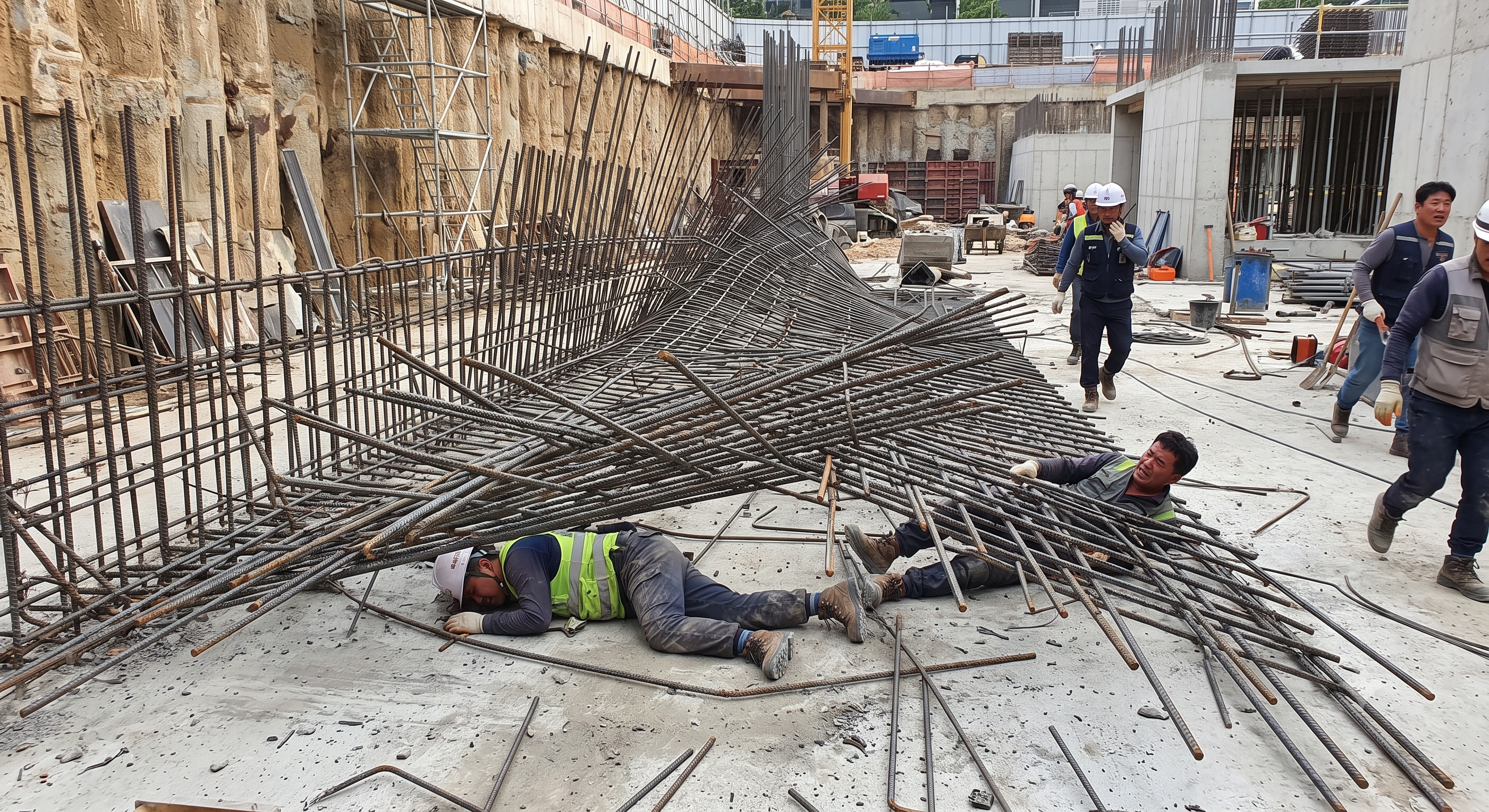
Retained educational illustration; not evidence of an actual incident.
The scenario and record comparisons are fictional teaching examples, not records of real incidents, measurements, inspections, signatures or approvals.
| Item | Fictional scenario |
|---|---|
| Initial situation | A fictional crew positions a wall cage and asks to free the crane for the next load. |
| Changed condition | Only the first planned brace is fitted; the second anchor has not been checked. |
| Reason to stop | A supervisor notices movement and stops the proposed hook release before anyone approaches the cage. |
| Immediate action | Keep people outside the potential fall area and have the temporary-works designer resolve support and sequence. |
| Prevention barrier | Restart only after the specified braces, foundations and connections are checked and the release is recorded. No injury, measurement or actual accident is asserted. |
Failure mechanisms
Tying wire locates bars and may contribute to cage behaviour, but its presence alone does not establish stability during lifting or before concreting. The temporary load path must include the cage, braces, connections and supporting ground or slab.
A tall cage can be affected by eccentric lifting, contact, wind and changes to access or ties. An assumed cantilever formula or a single height threshold cannot replace design of the actual assembly and construction sequence.
Small scratch-protection caps are not automatically impalement protection. Assess the possible fall, support spacing, product suitability and installation of guards or trough systems; colour or a metal insert alone does not demonstrate performance.
Decision sequence
| Decision stage | What to verify |
|---|---|
| Known facts | Check the current drawing and identify who may authorise temporary-support changes. |
| Unresolved matters | Confirm mass, lifting points, sling arrangement, crane radius and landing capacity. |
| Reason to hold | Provide protected access and install the specified braces without entering a crush zone. |
| Required evidence | Check the complete support path while the planned lifting support remains available; do not improvise crane support after instability develops. |
| Restart decision | Release the hook only through the agreed sequence, then retain and inspect bracing until a separate authorised removal point. |
5. Conditional decisions and common errors
| Condition | Action | Evidence | Proceed when |
|---|---|---|---|
| Brace missing | Hold hook release; clear the fall area. | Drawing, brace and anchor checks. | All designed braces checked |
| Machine jam | Stop, isolate and prevent restart. | Isolation check and safe clearing method. | Isolation verified |
| End protection damaged | Close the exposed route and replace protection. | Product suitability and installation check. | Protection restored |
| Wind or layout changes | Suspend affected work and review design limits. | Weather and revised sequence record. | Revised limits satisfied |
Similar situations, different decisions
The scenario and record comparisons are fictional teaching examples, not records of real incidents, measurements, inspections, signatures or approvals.
| Comparison | Situation A | Situation B |
|---|---|---|
| Hook release | A tied cage is assumed self-supporting. | Release follows the designed brace and anchor checks. |
| Bar end protection | A bright cap is treated as fall protection. | The guard is suitable for the actual impalement risk. |
| Clearing a bender | The emergency stop is pressed, then a hand reaches in. | Energy is isolated and restart prevented before safe clearing. |
6. Roles and responsibilities
| Role | Responsibility |
|---|---|
| Work supervisor | Coordinate deck loads, access routes, adjacent trades and hold points; record who controls changes. |
| Technical reviewer | Design or review temporary support and lifting details within professional competence; resolve changes before use. |
| Work crew | Operate only equipment for which competent and authorised; check guards, lifting gear and agreed signals. |
| Inspector / assessor | Inspect the physical installation and evidence; report deviations without inventing a technical approval. |
| Release / handover authority | Explain stop signals and exclusions to the crew, including subcontractors, and confirm the handover boundary. |
Supervision, records, handover
| Job stage | Technical and procedural controls | Site verification |
|---|---|---|
| Plan sequence | 1. Assign design checker2. Approve support sequence3. Control drawing changes | 1. Design responsibility2. Current revision3. Change log |
| Receive / store | 1. Allocate stock area2. Set stack load limit3. Assign unloading control | 1. Storage plan2. Load limit3. Traffic separation |
| Cut / bend | 1. Assign trained operators2. Define isolation method3. Schedule guard checks | 1. Training record2. Isolation procedure3. Defect close-out |
| Lift bundles | 1. Approve lift arrangement2. Coordinate work window3. Name signal controller | 1. Lift plan revision2. Crew briefing3. Capacity evidence |
| Place / brace | 1. Hold hook release2. Check installed supports3. Authorise support changes | 1. Brace inspection2. Anchor evidence3. Release record |
| Clean / hand over | 1. Record retained braces2. Transfer open defects3. Define removal authority | 1. Handover record2. Protection status3. Removal hold point |
7. Hold points and record comparison
| Hold point | Evidence before release | Confirmation / approval |
|---|---|---|
| Start | Receiving, storing, cutting, bending, lifting, placing, tying and handing over conventional reinforcement. Use the actual cage geometry, bundle mass, deck capacity, lifting arrangement and machine model to complete the assessment with the crew. | |
| HP-1 Cut / bend | Guard test · Sweep area clear · Feed support ready · Isolation verified | |
| HP-2 Lift bundles | Lift plan checked · Capacity checked · Signals agreed · Gear compatible | |
| HP-3 Place / brace | Braces installed · Connections checked · Release authorised · Weather acceptable | |
| HP-4 Clean / hand over | Walkway clear · Waste contained · Protection intact · Handover recorded |
Complete after actual checks. Recheck after changes, defects or shift handover.
Record comparison examples
The scenario and record comparisons are fictional teaching examples, not records of real incidents, measurements, inspections, signatures or approvals.
The boxes are static record prompts, not interactive or saved approvals. A tick does not establish suitability or permission to restart. Record the evidence, person, time and unresolved issues; retain the change history.
| Record type | Insufficient record | Record checklist |
|---|---|---|
| Cut / bend | Only OK | □ Guard test□ Sweep area clear□ Feed support ready□ Isolation verified |
| Lift bundles | Only OK | □ Lift plan checked□ Capacity checked□ Signals agreed□ Gear compatible |
| Place / brace | Only OK | □ Braces installed□ Connections checked□ Release authorised□ Weather acceptable |
| Clean / hand over | Only OK | □ Walkway clear□ Waste contained□ Protection intact□ Handover recorded |
8. Site checklist and emergency response
| Check item | Result | Person / action |
|---|---|---|
| □ Plan sequence: Drawing revision | ||
| □ Receive / store: Bearing checked | ||
| □ Cut / bend: Guard test | ||
| □ Lift bundles: Lift plan checked | ||
| □ Access / ends: Access inspected | ||
| □ Place / brace: Braces installed | ||
| □ Tie / inspect: Tie pattern checked | ||
| □ Clean / hand over: Walkway clear | ||
| □ Release / handover authority |
Stop work
Stop for an unverified lifting point, unknown load or deck capacity, ineffective guard, lost signals, missing brace, damaged end protection or weather outside the design limits. Keep people out and resolve the cause before a fresh release.
Emergency response
Raise the site alarm, stop nearby plant where safe and isolate the area. Do not approach a moving or unstable cage, improvise a rescue lift or remove an impaled object. Call the site emergency response and provide the location and access route; trained responders use the site rescue plan.
9. Sources and review limits
2026-10-11
| Source | Scope and limitations |
|---|---|
| HSE: Temporary works | Reviewed public guidance on temporary-works planning and responsibility; no site design verified. |
| HSE: PUWER overview | Reviewed machinery protection hierarchy; guard selection depends on the actual hazard and equipment. |
| HSE: Inspection | Reviewed risk-based inspection guidance; do not claim every interlock has an identical statutory daily test. |
| OSHA: Rebar guarding interpretation, 1997 | Foreign historical interpretation concerning inadequate small mushroom caps; no product is certified by this article. |
This is reference content written and revised with AI. It has not been verified or approved by a professional. Review by a suitably qualified professional and site authorisation are required before use.
10. PDF guidance and FAQ
PDF A covers basic task controls; B focuses on technical failures; C covers supervision, records and handover. The article has eight stages with four items per main cell; each PDF has six key stages with three items per main cell. P/S/R/A, measurements, confirmations and signatures remain blank for actual site assessment.
Content group ID
jsa-rebar-work
Can tying wire replace designed bracing?
No. Confirm the stability of the actual cage and its temporary supports through the construction sequence; do not infer it from the quantity of ties.
Are all rebar caps suitable for a fall onto steel?
No. Guarding must address the actual impalement hazard. Check product capability, support and installation; a scratch cap or colour is not proof.
Does an emergency stop make a jam safe to clear?
No. Isolate the relevant energy, prevent restart and control stored energy before the authorised clearing method.
When may braces be removed?
Only at the documented release point after the responsible person has verified the specified permanent or replacement support. Finishing the tying is not sufficient.
Has a professional verified or approved this document?
No. Public sources and editorial, layout and consistency checks were reviewed using AI. No site inspection or professional technical approval has been performed. Obtain appropriate professional review before use.
11. Revision history and authorship
This is reference content written and revised with AI. It has not been verified or approved by a professional. Review by a suitably qualified professional and site authorisation are required before use.
| Date | Version | Change | Review status |
|---|---|---|---|
| 2026-07-22 | Original version unmarked | Original preserved | No professional approval |
| 2026-10-11 | 1.1 | Decisions, records, JSA and PDFs revised | No professional approval |
Unverified original incident narratives and precise event figures are replaced with an explicitly fictional decision exercise. Universal dimensions and implied platform or expert certification are removed. Valid controls for dunnage, guarding, rigging, protected access, bracing, bar ends and offcut collection remain. The complete original and its references are retained in the recovery archive; changed legal references are explained in the source review. LOLER is no longer cited as a universal brace/cap rule, and BS 8666 is not used to certify fall-protection anchors.