Control the temporary load path before allowing the next movement. This revision links the existing crane-specific hazards to evidence at connection opening, each hydraulic stroke, mast insertion and final release. The eight rows group activities; they do not prescribe the mechanical sequence for an unidentified crane.
This is reference content written and revised with AI. It has not been verified or approved by a professional. Review by a suitably qualified professional and site authorisation are required before use.
Stop work
Stop for missing support confirmation, abnormal pressure or movement, guide binding, loss of communication, weather outside the approved envelope, an incomplete connection or entry into the exposure zone. Stop progressing the sequence; keep the system in its prescribed holding condition.
1. Legal and technical scope
| Basis | Application limits |
|---|---|
| HSE - Planning lifting operations | Risk-based planning, strength, stability, positioning and supervision. |
| HSE - Thorough examinations | Competent examination, assembly/installation and exceptional circumstances; a crew checklist does not replace the required examination. |
Great Britain: HSE explains competent planning, supervision and required thorough examinations. Northern Ireland has separate legislation. BS 7121 is not treated as legislation and its licensed clauses were not read. Determine the applicable LOLER examination arrangements after the configuration change.
2. Scope and required inputs
Use the exact manufacturer climbing manual, approved configuration and jurisdiction-specific engineering documents. No actual model manual or site calculations were supplied. Do not infer wind limits, torque, support capacity, free-standing height or a pin-removal sequence from this guide. A support may carry hydraulic load during a prescribed stroke; mechanical transfer is required at the stages specified for that system.
| Required input | What to verify |
|---|---|
| Plan | Does every document identify the same crane and final configuration?; Are current foundation, tie and temporary-works calculations attached?; Have simultaneous operations and public interfaces been controlled?; Are all permit signatures and competence records complete? |
| Weather | Are current and forecast wind conditions recorded at the permit issue point?; Is the wind indicator functioning and visible to the responsible person?; Are barriers, access controls and signage physically in place?; Can every crew member repeat the emergency-stop signal? |
| Inspect | Has the inspection record been signed and accepted?; Are hydraulic test results within the manufacturer's limits?; Are component identification marks traceable to the approved procedure?; Are all safety-critical defects formally closed? |
| Balance | Is the balance position measured and independently confirmed?; Does the slew-restraint arrangement match the manufacturer's instructions?; Are the balance load and lifting accessories identified and secure?; Are adjacent operations stopped or positively coordinated? |
| Each stroke | Are all pawls, shoes or stools visibly and positively seated?; Is the load supported mechanically before the next hydraulic movement?; Are personnel clear of crush, trapping and shear points?; Are pressure, stroke and alignment readings normal? |
| Insert | Does the mast-section identification match the approved configuration?; Are lifting points and accessories inspected and correctly connected?; Is the section controlled without exposing personnel to trapping?; Is positive retention confirmed before de-rigging? |
| Connect | Are fastener grade, size, batch and condition correct?; Is the torque or tension equipment within calibration?; Has every connection received the required initial and final check?; Are locking devices fully installed and inspection-marked? |
| Release | Are the crane height, tie arrangement and configuration records updated?; Are all climbing equipment and temporary restraints accounted for?; Has the competent person confirmed any required examination?; Is the signed release-to-service record available to the operator? |
2.1 Scope
This guide applies to planned tower crane alteration-of-height operations involving:
- internal or external climbing frames;
- telescoping or jacking of the crane upper structure;
- lifting, transferring and inserting mast sections;
- temporary support on climbing pawls, shoes, stools or frames;
- hydraulic cylinder extension and retraction;
- mast-bolt, pin or connection installation;
- changes to tie or anchorage configuration; and
- post-climb inspection and return to service.
It does not provide a universal operating sequence. The sequence must come from the approved, crane-specific manufacturer procedure and engineered climbing plan.
2.2 Minimum Permit Attachments
The permit issuer should verify that the following current documents are attached or cross-referenced:
- crane make, model, serial number and asset identifier;
- current crane configuration and intended post-climb height;
- manufacturer climbing procedure and revision number;
- lifting plan and climbing method statement;
- task-specific risk assessment and JSA;
- climbing-frame and hydraulic-system inspection records;
- relevant LOLER thorough-examination reports;
- outstanding-defect and maintenance records;
- foundation, tie and anchorage calculations;
- mast and tie elevation drawings;
- temporary-works design checks and design-check category where applicable;
- mast-section and connection-hardware identification;
- bolt-tightening or pin-installation specification;
- weather forecast and wind-monitoring arrangements;
- exclusion-zone and lifting-zone drawing;
- communications and emergency-stop plan;
- work-at-height and rescue plan;
- personnel competence and authorisation records; and
- post-climb inspection and release-to-service requirements.
3. Eight-stage JSA
| Job stage | Hazards and effects | Failure factors | Technical and procedural controls | Site verification | P | S | R | A |
|---|---|---|---|---|---|---|---|---|
| 1. Plan | 1. Incorrect crane model, configuration or climbing sequence2. Unassessed structural reactions causing tower, tie or foundation failure3. Conflicting lifting operations, public interfaces or electrical hazards4. Unqualified personnel directing safety-critical steps | 1. Using a generic method statement without the current manufacturer procedure2. Missing temporary-works calculations or design approval3. No nominated person with authority to stop the operation4. Permit documents showing conflicting crane heights or mast types | 1. Verify the crane make, model, serial number, configuration and climbing-system identity2. Approve crane-specific RAMS, lifting plan and engineered climbing sequence3. Confirm manufacturer prohibitions, hold points and abnormal-condition instructions4. Name the Appointed Person, Crane Supervisor, specialist climbing supervisor and authorised crew | 1. Does every document identify the same crane and final configuration?2. Are current foundation, tie and temporary-works calculations attached?3. Have simultaneous operations and public interfaces been controlled?4. Are all permit signatures and competence records complete? | ||||
| 2. Weather | 1. Wind-induced jib movement, frame racking or suspended mast-section swing2. Lightning, poor visibility, rain, ice or slippery access surfaces3. Falling objects striking personnel below4. Unauthorised entry into the climbing or lifting zone | 1. Assuming a generic wind limit applies to every crane2. Monitoring average wind while ignoring gusts at crane level3. Using cones or tape without controlled access4. No common emergency-stop signal or loss-of-radio procedure | 1. Record the manufacturer's climbing wind limit and any lower project limit2. Provide a functioning anemometer or approved wind-measurement method at the specified location3. Define warning, stop-work, securing and restart criteria4. Establish a guarded exclusion zone covering credible drop, swing and collapse envelopes | 1. Are current and forecast wind conditions recorded at the permit issue point?2. Is the wind indicator functioning and visible to the responsible person?3. Are barriers, access controls and signage physically in place?4. Can every crew member repeat the emergency-stop signal? | ||||
| 3. Inspect | 1. Cracked, distorted or incorrectly assembled climbing-frame components2. Hydraulic hose rupture, leakage or uncontrolled cylinder movement3. Failure of check valves, pressure-limiting devices, pawls or support shoes4. Damaged access platforms, guardrails or anchor points | 1. Accepting components by appearance without positive identification2. Operating with unresolved hydraulic leakage or damaged hoses3. Bypassing interlocks, valves or pressure controls4. Using substituted pins, bolts, hoses or fittings without approval | 1. Complete a documented inspection by competent personnel2. Verify the condition and identity of cylinders, hoses, fittings, pins, rollers, pawls, guides and supports3. Function-test check valves, pressure limits, controls and emergency stops as specified4. Quarantine damaged, incompatible or unidentified components | 1. Has the inspection record been signed and accepted?2. Are hydraulic test results within the manufacturer's limits?3. Are component identification marks traceable to the approved procedure?4. Are all safety-critical defects formally closed? | ||||
| 4. Balance | 1. Unbalanced upper structure causing mast binding or frame distortion2. Unintended slewing due to wind or incorrect brake configuration3. Dropped or swinging balance load4. Collision with nearby cranes, structures or power lines | 1. Estimating trolley position or balance radius by eye2. Using a slew brake as a mechanical lock where this is not approved3. Applying a universal slew-lock arrangement to an incompatible crane4. Failing to control adjacent cranes or obstructions | 1. Place the trolley and any balance load at the manufacturer-defined position and radius2. Orient the jib and counter-jib exactly as required by the approved climbing procedure3. Apply the model-specific slew-restraint, brake or locking arrangement4. Verify clearances and coordinate adjacent crane and site operations | 1. Is the balance position measured and independently confirmed?2. Does the slew-restraint arrangement match the manufacturer's instructions?3. Are the balance load and lifting accessories identified and secure?4. Are adjacent operations stopped or positively coordinated? | ||||
| 5. Each stroke | 1. Sudden descent from hydraulic or support-system failure2. Uneven lifting causing mast or climbing-frame binding3. Hands or body parts trapped at moving interfaces4. Overstroke, excessive pressure or support engagement failure | 1. Supporting the structure on hydraulic pressure alone2. Advancing without confirming both support points are fully engaged3. Workers positioned inside pinch or shear zones4. Continuing after abnormal noise, movement, pressure or alignment | 1. Follow the approved stroke-by-stroke load-transfer sequence2. Establish positive mechanical support before releasing hydraulic load where required3. Use one designated controller and one agreed command system4. Stop immediately for asymmetric movement, binding, pressure loss, leakage or incomplete engagement | 1. Are all pawls, shoes or stools visibly and positively seated?2. Is the load supported mechanically before the next hydraulic movement?3. Are personnel clear of crush, trapping and shear points?4. Are pressure, stroke and alignment readings normal? | ||||
| 6. Insert | 1. Suspended mast section striking the tower, climbing frame or personnel2. Load swing or rotation under changing wind conditions3. Incorrect mast-section type, orientation or connection interface4. Falling tools, pins or loose components | 1. Personnel standing beneath or inside the suspended-load path2. Using uncontrolled hand contact instead of approved positioning aids3. Inserting an unidentified or incompatible mast section4. Removing lifting accessories before positive retention is achieved | 1. Inspect and positively identify the mast section before lifting2. Use approved lifting points, accessories and tag-line arrangements3. Maintain the exclusion zone and control access throughout transfer4. Secure the section against displacement before detaching lifting accessories | 1. Does the mast-section identification match the approved configuration?2. Are lifting points and accessories inspected and correctly connected?3. Is the section controlled without exposing personnel to trapping?4. Is positive retention confirmed before de-rigging? | ||||
| 7. Connect | 1. Connection failure causing loss of tower continuity or structural collapse2. Incorrect bolts, pins, nuts or locking devices3. Under-tightening, over-tightening or inconsistent preload4. Trapping and dropped-object hazards during connection work | 1. Reusing fasteners where reuse is not permitted2. Using uncalibrated or unsuitable torque equipment3. Applying generic torque values instead of the approved specification4. Failing to document each completed connection | 1. Use only manufacturer-approved and traceable connection hardware2. Clean, inspect, lubricate or keep dry as required by the specified tightening method3. Apply the approved torque, tension, turn-of-nut or pin-retention procedure4. Conduct independent inspection and record each accepted connection | 1. Are fastener grade, size, batch and condition correct?2. Is the torque or tension equipment within calibration?3. Has every connection received the required initial and final check?4. Are locking devices fully installed and inspection-marked? | ||||
| 8. Release | 1. Crane operation with incomplete connections or retained climbing restraints2. Tools or materials left within the tower or machinery deck3. Incorrect limits, indicators or safety devices after configuration change4. Use before required inspection or examination is completed | 1. Relying on a verbal completion statement without documented checks2. Removing the exclusion zone before the crane is structurally complete3. Failing to update height, tie or configuration records4. Allowing production lifting before formal release | 1. Complete a systematic tool, material and personnel check2. Restore guards, access systems, restraints, limits and safety devices3. Perform required post-climb inspections, tests and examinations4. Issue written release to service only after all hold points and defects are closed | 1. Are the crane height, tie arrangement and configuration records updated?2. Are all climbing equipment and temporary restraints accounted for?3. Has the competent person confirmed any required examination?4. Is the signed release-to-service record available to the operator? |
PDF A covers basic task controls; B focuses on technical failures; C covers supervision, records and handover. The article has eight stages with four items per main cell; each PDF has six key stages with three items per main cell. P/S/R/A, measurements, confirmations and signatures remain blank for actual site assessment.
Use the exact manufacturer climbing manual, approved configuration and jurisdiction-specific engineering documents. No actual model manual or site calculations were supplied. Do not infer wind limits, torque, support capacity, free-standing height or a pin-removal sequence from this guide. A support may carry hydraulic load during a prescribed stroke; mechanical transfer is required at the stages specified for that system.
4. Fictional scenario and failure mechanisms
The scenario and record comparisons are fictional teaching examples, not records of real incidents, measurements, inspections, signatures or approvals.
The original educational image is retained. It is not evidence of an actual incident or site suitability.
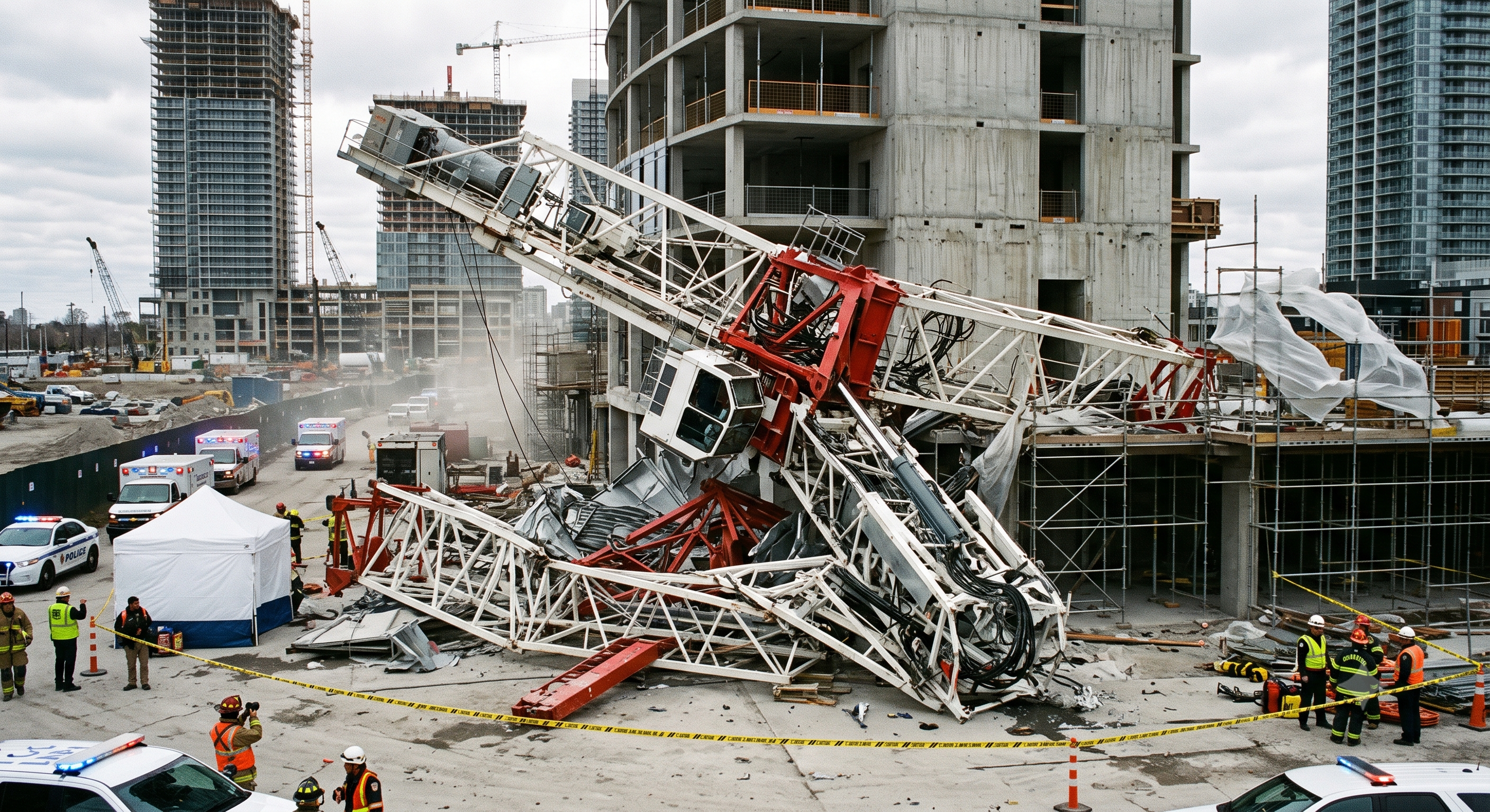
Training scenario only: The following is a hypothetical example and is not presented as a report of an actual HSE investigation or incident.
A climbing crew prepares to add a mast section to a tower crane. The generic RAMS states a wind limit but does not identify whether the value applies to mean wind, gust speed or measurement at crane level. The trolley balance position is copied from a different crane configuration.
During jacking, the upper structure becomes slightly out of balance. One side of the climbing frame lifts before the other, creating binding and elevated hydraulic pressure. The crew continues because the pressure remains below the relief-valve setting.
A gust then moves the jib and the suspended mast section. The climbing frame racks, one support pawl does not fully seat, and a worker attempts to correct the engagement manually while the system remains loaded.
Barrier Failures
- Planning barrier failure: the climbing plan was not verified against the actual crane configuration.
- Weather-control failure: no clear gust limit or crane-level measurement method was established.
- Balance-control failure: the trolley position was not measured against the manufacturer's configuration.
- Load-transfer failure: the next step began without positive confirmation of both support engagements.
- Human-positioning failure: personnel entered a trapping zone while stored and suspended energy remained.
- Stop-work failure: abnormal pressure and asymmetric movement did not trigger an immediate stop.
Required Learning Actions
- Treat configuration, wind, balance and pawl engagement as independent permit hold points.
- Stop for unexpected movement, noise, binding, leakage or pressure change.
- Do not use hands, bars or improvised tools to correct engagement while the system is loaded.
- Secure the crane in accordance with the manufacturer's abnormal-condition procedure.
- Resume only after the defect and its cause have been investigated and the responsible competent persons have reauthorised the work.
5. Conditional decisions and common errors
| Condition | Action | Evidence | Proceed when |
|---|---|---|---|
| Before opening | Balance, restraint and temporary support not confirmed | Keep connections intact; resolve missing evidence | All three verified |
| Every stroke | A support is only partly seated | Stop; use the model contingency | All required seats confirmed |
| Section transfer | Section aligned but not positively retained | Keep approved handling support in place | Restraint accepted |
| Interrupted climb | Weather recovers but defect remains | Keep work suspended; inspect the affected state | Cause and hold points closed |
| Return to service | Bolts complete but tests pending | Retain operational prohibition | Required inspections accepted |
Similar situations, different decisions
| Comparison | Situation A | Situation B |
|---|---|---|
| Balance | A level reading alone | Model method, load/radius, orientation and checker recorded |
| Support | Pressure appears steady | Each specified bearing and retainer checked at the named stroke |
| Connection | Paint mark present | Hardware, method, tool and acceptance result traceable |
| Handover | Crew says complete | Final configuration, tests, defects and release authority recorded |
Use the exact manufacturer climbing manual, approved configuration and jurisdiction-specific engineering documents. No actual model manual or site calculations were supplied. Do not infer wind limits, torque, support capacity, free-standing height or a pin-removal sequence from this guide. A support may carry hydraulic load during a prescribed stroke; mechanical transfer is required at the stages specified for that system.
5.1 Crane-Specific Climbing Procedure
The permit must reference the current procedure for the exact crane and climbing system. Generic diagrams, previous-project method statements and procedures for similar crane models must not be treated as substitutes.
The climbing supervisor must brief the crew on:
- the sequence of operations;
- personnel positions;
- control commands;
- balance configuration;
- mechanical support stages;
- prohibited actions;
- stop-work triggers; and
- emergency securing steps.
5.2 Wind and Weather Control
There is no universal statutory wind-speed number applicable to every tower crane climbing operation in Great Britain.
The permit must record:
- the manufacturer's maximum permitted climbing wind speed;
- whether the limit is an average, instantaneous or gust value;
- the required measurement height and location;
- instrument type and inspection or calibration status;
- warning and stop-work levels;
- forecast monitoring arrangements;
- lightning, visibility, rain, ice and temperature restrictions; and
- securing and restart requirements.
If different documents specify different limits, the lowest safe applicable limit must be used until the discrepancy is resolved.
5.3 Structural and Temporary-Works Control
Before climbing, verify that:
- the foundation remains adequate for the revised crane condition;
- mast-section type, strength class and orientation are correct;
- ties, collars, anchorages and building reactions match the design;
- free-standing height and tie spacing remain within approved limits;
- construction progress provides the assumed structural capacity;
- no unauthorised attachments or modifications affect the crane;
- the intended temporary climbing states have been assessed; and
- design changes have been reviewed through the project's temporary-works procedure.
5.4 Hydraulic and Mechanical Support Control
Hydraulic pressure must not be treated as the sole means of supporting a raised structure unless the manufacturer has expressly designed and authorised that condition.
At every load-transfer stage:
- Stop hydraulic movement.
- Confirm alignment.
- Verify the required pawls, shoes, stools or locking devices are fully engaged.
- Transfer load in the specified manner.
- Confirm stable mechanical support.
- Proceed only after the designated checker authorises the next movement.
5.5 Mast Connection Control
Connection acceptance must address:
- correct fastener or pin specification;
- manufacturer limitations on reuse;
- contact-surface condition;
- required lubrication condition;
- tightening sequence;
- torque, tension or other specified value;
- calibrated tools;
- pin-retention and locking arrangements;
- independent verification; and
- traceable completion records.
Torque alone is not a universal acceptance method. Use the connection method specified by the manufacturer or approved engineering documentation.
5.6 Work at Height and Rescue
The work-at-height system must identify:
- collective protection provided by platforms, guardrails and gates;
- approved access routes;
- personal fall-protection equipment where required;
- suitable anchor points and connection methods;
- controls for transitions between platforms and mast sections;
- prevention of dropped tools and materials;
- rescue equipment;
- trained rescuers;
- casualty recovery routes; and
- suspension-intolerance considerations.
The rescue plan must be practised or otherwise validated as practicable for the crane configuration and site conditions.
5.7 Exclusion-Zone Control
The exclusion zone must be based on the actual operation rather than a universal radius.
Consider:
- mast-section lifting and transfer routes;
- suspended-load swing;
- falling tools and components;
- jib and counter-jib movement;
- climbing-frame and mast collapse envelopes;
- adjacent buildings and occupied areas;
- public roads and footpaths;
- nearby cranes and plant; and
- evacuation routes.
Access must be limited to authorised personnel with an operational need to enter.
Technical failure review
| Job stage | Hazards and effects | Failure factors | Technical and procedural controls | Site verification |
|---|---|---|---|---|
| Plan | 1. Wrong model2. Tie failure3. Crew conflict | 1. Wrong revision2. Unchecked support3. Unassigned command | 1. Match crane and frame2. Approve temporary states3. Assign one director | 1. Manual revision2. Tie design3. Crew authority |
| Weather | 1. Wind torsion2. Falling objects3. Collision | 1. Ground-only reading2. Open boundary3. No securing plan | 1. Set model wind limits2. Control full exposure zone3. Plan safe interruption | 1. Wind basis2. Boundary map3. Securing method |
| Inspect | 1. Hydraulic drift2. Guide failure3. Falls | 1. Leaking circuit2. Worn support3. Unsafe platform | 1. Inspect valves and hoses2. Check guides and supports3. Verify access and rescue | 1. Test record2. Support condition3. Rescue readiness |
| Balance | 1. Eccentric moment2. Unwanted slew3. Support overload | 1. Wrong radius2. Wrong ballast3. Premature release | 1. Set prescribed balance2. Verify slew restraint3. Hold before opening mast | 1. Load and radius2. Restraint state3. Temporary load path |
| Each stroke | 1. Support slip2. Ram side load3. Crushing | 1. Partial seating2. Conflicting signals3. Ignored binding | 1. Follow model sequence2. Check every load transfer3. Stop on abnormal motion | 1. All support seats2. Stroke and pressure3. People clear |
| Insert | 1. Dropped section2. Transfer runaway3. Trapped hands | 1. Wrong section2. Missing end stop3. Forced alignment | 1. Match section and rigging2. Secure before detaching3. Use approved alignment | 1. Section identity2. Stops and retainers3. Temporary restraint |
| Connect | 1. Mast separation2. Fastener damage3. Dropped tools | 1. Wrong hardware2. Uncontrolled tightening3. Matchmarks only | 1. Apply specified method2. Check every connection3. Hold before load change | 1. Part and reuse rule2. Tool and results3. Independent check |
| Release | 1. Premature use2. Loose components3. Limit failure | 1. Open defects2. Old configuration3. Verbal handover | 1. Restore operating state2. Complete required tests3. Authorise return to use | 1. Final configuration2. Defect closure3. Release record |
6. Roles and responsibilities
| Role | Minimum Responsibilities |
|---|---|
| Client / Principal Contractor | Ensure suitable project arrangements, resources, coordination and site controls are provided under CDM 2015. |
| Appointed Person — Lifting Operations | Develop or approve the lifting plan within the limits of competence; identify resources, interfaces and lifting controls. |
| Crane Supervisor | Supervise implementation of the lifting plan and stop the operation if the plan cannot be followed safely. |
| Specialist Climbing or Erection Supervisor | Direct the manufacturer's climbing sequence, control hold points and coordinate the specialist erection crew. |
| Tower Crane Operator | Operate only within the approved procedure, respond to the designated signaller and stop for unsafe or unclear conditions. |
| Slinger/Signaller | Inspect and connect lifting accessories, control mast-section movements and provide agreed signals. |
| Climbing/Erection Crew | Follow the climbing procedure, use approved access and fall protection, verify connections and report defects immediately. |
| Temporary Works Coordinator | Coordinate the temporary-works process, including design briefs, checks, permits and implementation controls. |
| Structural or Temporary-Works Engineer | Assess foundations, ties, anchorages, reactions and temporary configurations within the person's professional competence. |
| Competent Person for Thorough Examination | Determine and undertake the examinations required by LOLER, independently of production pressure. |
| Permit Issuer | Confirm that attachments, controls and signatures are complete before releasing each permit stage. |
| Site Management | Control exclusion zones, simultaneous operations, emergency arrangements and communication with affected parties. |
A single person may perform more than one role only where that person has the required competence, authority, capacity and independence for each duty.
Supervision, records, handover
| Job stage | Technical and procedural controls | Site verification |
|---|---|---|
| Work package | 1. Index the approved documents2. Name competent roles3. Brief rescue and stop rules | 1. Manual revision2. Tie design3. Crew authority |
| External controls | 1. Assign wind and access watch2. Record current conditions3. Confirm one radio channel | 1. Wind basis2. Boundary map3. Securing method |
| Witness inspection | 1. Witness critical inspections2. Quarantine rejected parts3. Close defects before release | 1. Test record2. Support condition3. Rescue readiness |
| Balance release | 1. Witness balance and restraint2. Record independent check3. Control connection release | 1. Load and radius2. Restraint state3. Temporary load path |
| Stroke command | 1. Log every stroke and support2. Confirm commands received3. Suspend on any uncertainty | 1. All support seats2. Stroke and pressure3. People clear |
| Final acceptance | 1. Separate installer and checker2. Accept tests and defect closure3. Record operating release | 1. Final configuration2. Defect closure3. Release record |
7. Hold points and record comparison
| Hold point | Evidence before release | Confirmation / approval |
|---|---|---|
| Start | Use the exact manufacturer climbing manual, approved configuration and jurisdiction-specific engineering documents. No actual model manual or site calculations were supplied. Do not infer wind limits, torque, support capacity, free-standing height or a pin-removal sequence from this guide. A support may carry hydraulic load during a prescribed stroke; mechanical transfer is required at the stages specified for that system. | |
| HP-1 Balance | Is the balance position measured and independently confirmed?; Does the slew-restraint arrangement match the manufacturer's instructions?; Are the balance load and lifting accessories identified and secure?; Are adjacent operations stopped or positively coordinated? | |
| HP-2 Each stroke | Are all pawls, shoes or stools visibly and positively seated?; Is the load supported mechanically before the next hydraulic movement?; Are personnel clear of crush, trapping and shear points?; Are pressure, stroke and alignment readings normal? | |
| HP-3 Connect | Are fastener grade, size, batch and condition correct?; Is the torque or tension equipment within calibration?; Has every connection received the required initial and final check?; Are locking devices fully installed and inspection-marked? | |
| HP-4 Release | Are the crane height, tie arrangement and configuration records updated?; Are all climbing equipment and temporary restraints accounted for?; Has the competent person confirmed any required examination?; Is the signed release-to-service record available to the operator? |
Complete after actual checks. Recheck after changes, defects or shift handover.
Record comparison examples
The boxes are static record prompts, not interactive or saved approvals. A tick does not establish suitability or permission to restart. Record the evidence, person, time and unresolved issues; retain the change history.
| Record type | Insufficient record | Record checklist |
|---|---|---|
| Weather | Verbal or undated confirmation only | □ Wind basis□ Boundary map□ Securing method□ Manual section, time and checker |
| Balance | Verbal or undated confirmation only | □ Load and radius□ Restraint state□ Temporary load path□ Manual section, time and checker |
| Each stroke | Verbal or undated confirmation only | □ All support seats□ Stroke and pressure□ People clear□ Manual section, time and checker |
| Connect | Verbal or undated confirmation only | □ Part and reuse rule□ Tool and results□ Independent check□ Manual section, time and checker |
8. Site checklist and emergency response
| Check item | Result | Person / action |
|---|---|---|
| □ Plan: Does every document identify the same crane and final configuration? | ||
| □ Weather: Are current and forecast wind conditions recorded at the permit issue point? | ||
| □ Inspect: Has the inspection record been signed and accepted? | ||
| □ Balance: Is the balance position measured and independently confirmed? | ||
| □ Each stroke: Are all pawls, shoes or stools visibly and positively seated? | ||
| □ Insert: Does the mast-section identification match the approved configuration? | ||
| □ Connect: Are fastener grade, size, batch and condition correct? | ||
| □ Release: Are the crane height, tie arrangement and configuration records updated? | ||
| □ Release / handover authority |
Stop work
Stop for missing support confirmation, abnormal pressure or movement, guide binding, loss of communication, weather outside the approved envelope, an incomplete connection or entry into the exposure zone. Stop progressing the sequence; keep the system in its prescribed holding condition.
Emergency response
Do not automatically depressurise, reverse the ram, lower onto the nearest support or release a slew restraint. These actions can remove the current load path. Apply the manufacturer contingency for the actual stage, secure the area and obtain the responsible technical direction. Rescue must not depend on moving an unstable crane. Restart requires cause identification, correction, reinspection and repeat release of the affected hold points.
9. Sources and review limits
2026-10-08
Great Britain: HSE explains competent planning, supervision and required thorough examinations. Northern Ireland has separate legislation. BS 7121 is not treated as legislation and its licensed clauses were not read. Determine the applicable LOLER examination arrangements after the configuration change.
| Source | Scope and limitations |
|---|---|
| HSE - Planning lifting operations | Risk-based planning, strength, stability, positioning and supervision. |
| HSE - Thorough examinations | Competent examination, assembly/installation and exceptional circumstances; a crew checklist does not replace the required examination. |
Use the exact manufacturer climbing manual, approved configuration and jurisdiction-specific engineering documents. No actual model manual or site calculations were supplied. Do not infer wind limits, torque, support capacity, free-standing height or a pin-removal sequence from this guide. A support may carry hydraulic load during a prescribed stroke; mechanical transfer is required at the stages specified for that system.
10. PDF guidance and FAQ
PDF A covers basic task controls; B focuses on technical failures; C covers supervision, records and handover. The article has eight stages with four items per main cell; each PDF has six key stages with three items per main cell. P/S/R/A, measurements, confirmations and signatures remain blank for actual site assessment.
jsa-crane-telescoping
Does steady pressure prove safe support?
No. Identify the current load path and verify all supports and retainers required by the model before the next transfer. Pressure alone cannot confirm seating.
Can climbing resume as soon as wind drops?
No. Check the securing state, forecast, defects and changed configuration; repeat affected hold points before authorised restart.
Does a paint mark prove bolt preload?
No. Use the specified installation and verification method with traceable tooling and recorded results. Matchmarks are supplementary.
Are A/B/C separate operating procedures?
No. A summarises field controls, B examines mechanical failures, and C organises supervision and evidence. Read them with the full eight-stage body and actual manufacturer procedure.
Has a professional verified or approved this document?
No. Public sources and editorial, layout and consistency checks were reviewed using AI. No site inspection or professional technical approval has been performed. Obtain appropriate professional review before use.
11. Revision history and authorship
This is reference content written and revised with AI. It has not been verified or approved by a professional. Review by a suitably qualified professional and site authorisation are required before use.
Original body and three A/B/C downloads retained in recovery records; no numeric revision identified in their text or metadata. A/B/C describe perspectives, not chronological revisions. This dated revision is v1.1; it is an editorial revision without professional technical approval.
| Date | Version | Change | Review status |
|---|---|---|---|
| 2026-09-16 | A/B/C | Original preserved | No professional approval |
| 2026-10-08 | v1.1 | Decisions, records, JSA and PDFs revised | No professional approval |
Preserved the useful original controls and training scenario. Consolidated the original stages into eight without treating a grouped row as a machine operating sequence. Added explicit interruption/restart decisions, record comparisons and model-specific load-path limits. Original source links remain traceable in the recovery record; only the current review scope listed here is claimed.