The crane capacity label does not prove that a particular lift is safe. The actual configuration, worst working radius, support reactions and load retention must all match the lift plan before movement begins.
Mobile crane lifting
This is reference content written and revised with AI. It has not been verified or approved by a professional. Review by a suitably qualified professional and site authorisation are required before use.
Stop work
Stop for sling movement, unexpected tilt, ground settlement, a safety-device fault, loss of signal or departure from the planned envelope. Do not bypass a limiter or approach a suspended load to correct the arrangement.
1. Legal and technical scope
| Basis | Application limits |
|---|---|
| HSE - planning lifting operations | Great Britain official guidance: competence, planning and supervision; not a site lift plan. |
| HSE - safe lifting by machine | Official technical guidance on load weight, sling angle and a low trial lift. |
Great Britain: LOLER requires lifting operations to be properly planned by a competent person, appropriately supervised and carried out safely. PUWER duties and examination arrangements remain relevant. A CPCS/NPORS card is evidence to assess, not by itself proof of competence for every lift. Northern Ireland has a separate legal framework.
2. Scope and required inputs
Included scope
Stationary mobile-crane lifting: planning, support setup, pre-use checks, rigging, trial lift, transfer, landing and handover. Retains the original pump-unit lifting example as a clearly hypothetical training case.
Separate review
Tandem lifting, personnel lifting, pick-and-carry, lifting over occupied areas and work near power lines need additional task-specific planning. This reference does not supply a crane setup, electrical clearance or rigging design.
| Required input | What to verify |
|---|---|
| Plan lift | Mass and centre · Worst working radius · Power line plan · Landing design |
| Set supports | Support reactions · Ground capacity · Extension and level · Void assessment |
| Check crane | Inspection record · Device functions · Chart deductions · Repair release |
| Rig load | Rigging sketch · Leg loads and WLL · Edge contact · Component identity |
BS 7121, BS EN 1492, BS EN 13889 and CIRIA C703 full texts were not reviewed. No crane manual, ground design or site examination record was supplied. The original numeric claims are not retained as universal British legal limits.
3. Eight-stage JSA
| Job stage | Hazards and effects | Failure factors | Technical and procedural controls | Site verification | P | S | R | A |
|---|---|---|---|---|---|---|---|---|
| 1. Plan lift | 1. Load drop2. Crane overturn3. Power contact4. Public exposure | 1. Unknown gross mass2. Wrong duty chart3. Unmapped route4. Unclear roles | 1. Confirm load data2. Match configuration3. Plan full route4. Assign lifting team | 1. Mass and centre2. Worst working radius3. Power line plan4. Landing design | ||||
| 2. Set supports | 1. Ground failure2. Crane tilt3. Outrigger crush4. Buried service damage | 1. Weak subgrade2. Undersized mats3. Wrong extension4. Unseen void | 1. Verify ground2. Size support system3. Use matching chart4. Guard moving supports | 1. Support reactions2. Ground capacity3. Extension and level4. Void assessment | ||||
| 3. Check crane | 1. Rope failure2. Block collision3. Unplanned movement4. Load drop | 1. Defective rope2. Failed safety device3. Wrong reeving4. Open defect | 1. Inspect before use2. Test as instructed3. Verify reeving4. Quarantine defects | 1. Inspection record2. Device functions3. Chart deductions4. Repair release | ||||
| 4. Rig load | 1. Load slip2. Leg overload3. Sling cut4. Pin release | 1. Wrong load centre2. Shallow sling angle3. Sharp edge4. Wrong shackle loading | 1. Use planned lift points2. Rate actual hitch3. Fit edge protection4. Secure correct pins | 1. Rigging sketch2. Leg loads and WLL3. Edge contact4. Component identity | ||||
| 5. Trial lift | 1. Load tilt2. Brake slip3. Shock loading4. Rigger crush | 1. Unequal load share2. Load snagged3. Rapid hoisting4. Unsafe standing area | 1. Lift slowly as planned2. Pause near support3. Check grip and balance4. Lower if abnormal | 1. Clear separation2. No sling migration3. Brake holding4. Team clearance | ||||
| 6. Transfer load | 1. Electrical contact2. Crushing3. Load swing4. Collision | 1. Route changed2. Signal lost3. Wind effects4. Tagline snag | 1. Control full route2. Use agreed signals3. Observe weather limits4. Use planned guidance | 1. Clearance envelope2. Signal contact3. Wind and surface area4. Guide line route | ||||
| 7. Land and release | 1. Load overturn2. Finger crush3. Support failure4. Trapped sling | 1. Weak landing bed2. Early release3. Hands in gap4. Unknown stability | 1. Prepare landing bed2. Confirm stable support3. Keep hands clear4. Release without forcing | 1. Bearing and restraint2. Load fully supported3. Release authority4. Rigging free | ||||
| 8. Stow and hand over | 1. Hook snag2. Outrigger crush3. Delayed failure4. Vehicle strike | 1. Gear left hanging2. Blind retraction3. Defect not reported4. Route obstructed | 1. Stow as instructed2. Guide moving supports3. Record outstanding defects4. Clear departure route | 1. Transport condition2. People accounted for3. Defect ownership4. Handover scope |
PDF A covers basic task controls; B focuses on technical failures; C covers supervision, records and handover. The article has eight stages with four items per main cell; each PDF has six key stages with three items per main cell. P/S/R/A, measurements, confirmations and signatures remain blank for actual site assessment.
4. Fictional scenario and failure mechanisms
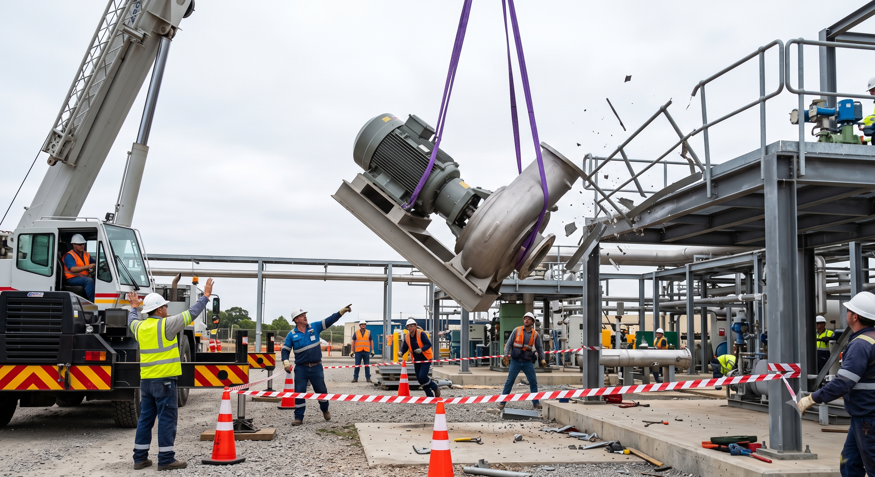
The original educational image is retained. It is not evidence of an actual incident or site suitability.
The scenario and record comparisons are fictional teaching examples, not records of real incidents, measurements, inspections, signatures or approvals.
| Item | Fictional scenario |
|---|---|
| Initial situation | A motor-pump skid is ready for lifting; its motor is offset from the frame centre. |
| Changed condition | The stated mass excludes the lifting beam and the load centre has not been confirmed. |
| Failure path | The crew proposes a direct lift because the crane has a large headline capacity. |
| Possible outcome | A sling could migrate on the painted casing while one leg takes more load than expected. |
| Prevention barrier | Hold the lift on its support, resolve gross load and lift-point geometry, then conduct the planned low trial lift. |
Failure mechanisms
For an ideal symmetric two-leg arrangement with equal sharing, T = W / (2 sin theta), with theta measured from horizontal and W the total force. This is not an exponential relationship and does not establish a universal failure angle. An offset centre, unequal leg stiffness or an unsuitable hitch invalidates equal-sharing assumptions; use rated hitch data and the planned geometry.
A load indicator does not measure ground bearing capacity or prevent sling slip. Ground reactions vary with radius, boom direction, counterweight and setup. Mat area alone cannot establish adequacy: mat bending, ground layers, voids and nearby excavations also matter.
Lift gently to the planned low trial position and check retention, balance and brake holding from a safe place. Stopping cannot correct a bad hitch. Lower to a prepared support before adjustment; do not pull a sling, push a rotating load or force a snag free.
Decision sequence
| Decision stage | What to verify |
|---|---|
| Known facts | The offset motor and unverified rigging are observable. |
| Unresolved matters | Gross lifted mass, centre of gravity, hitch capacity and landing stability remain unconfirmed. |
| Reason to hold | A nominal crane rating and a sling label cannot establish the capacity of this arrangement. |
| Required evidence | Obtain load evidence, configuration-specific chart with deductions, rigging sketch, support assessment and route/landing checks. |
| Restart decision | The designated lift supervisor releases only the checked stage after a satisfactory trial and team briefing; a changed radius or setup requires review. |
5. Conditional decisions and common errors
| Condition | Action | Evidence | Proceed when |
|---|---|---|---|
| Unknown mass | Hold on support | Load and gear evidence | Gross load known |
| Sling migration | Lower safely | Revised rigging sketch | Retention checked |
| Ground movement | Stop affected lift | Support reassessment | Stable setup |
| Lost signal | Stop movement | Communication restored | Route reconfirmed |
Similar situations, different decisions
The scenario and record comparisons are fictional teaching examples, not records of real incidents, measurements, inspections, signatures or approvals.
| Comparison | Situation A | Situation B |
|---|---|---|
| Capacity | Crane maximum tonnage: a headline rating. | Chart for actual radius and setup: relevant capacity evidence. |
| Trial | No movement for a moment: observation only. | Retention, balance, support and brakes checked: basis for next stage. |
| Landing | The load touches the base: partial contact. | Stable support and restraint: basis for de-rigging. |
6. Roles and responsibilities
| Role | Responsibility |
|---|---|
| Work supervisor | Coordinate the lift plan, exclusion zones and signals; stop at an unverified stage. |
| Technical reviewer | Provide competent load, ground, support and rigging assessment within the assigned scope. |
| Work crew | Operator, rigger and signal person work within their competence and agree who controls movement. |
| Inspector / assessor | Record actual inspections and observations; never prefill risk or acceptance results. |
| Release / handover authority | Accept the checked landing/handover scope and retain restrictions on outstanding defects. |
Supervision, records, handover
| Job stage | Technical and procedural controls | Site verification |
|---|---|---|
| Plan lift | 1. Assign lift scope2. Review load evidence3. Record boundaries | 1. Mass and centre2. Worst working radius3. Power line plan |
| Check crane | 1. Assign inspections2. Close safety defects3. Confirm device status | 1. Inspection record2. Device functions3. Chart deductions |
| Rig load | 1. Approve rigging sketch2. Check item identity3. Record load shares | 1. Rigging sketch2. Leg loads and WLL3. Edge contact |
| Trial lift | 1. Brief trial criteria2. Record observations3. Authorise next movement | 1. Clear separation2. No sling migration3. Brake holding |
| Land and release | 1. Identify landing bed2. Confirm stability3. Record release decision | 1. Bearing and restraint2. Load fully supported3. Release authority |
| Stow and hand over | 1. Assign defect owner2. Record final state3. Transfer restrictions | 1. Transport condition2. People accounted for3. Defect ownership |
7. Hold points and record comparison
| Hold point | Evidence before release | Confirmation / approval |
|---|---|---|
| Start | Stationary mobile-crane lifting: planning, support setup, pre-use checks, rigging, trial lift, transfer, landing and handover. Retains the original pump-unit lifting example as a clearly hypothetical training case. | |
| HP-1 Check crane | Inspection record · Device functions · Chart deductions · Repair release | |
| HP-2 Trial lift | Clear separation · No sling migration · Brake holding · Team clearance | |
| HP-3 Land and release | Bearing and restraint · Load fully supported · Release authority · Rigging free | |
| HP-4 Stow and hand over | Transport condition · People accounted for · Defect ownership · Handover scope |
Complete after actual checks. Recheck after changes, defects or shift handover.
Record comparison examples
The scenario and record comparisons are fictional teaching examples, not records of real incidents, measurements, inspections, signatures or approvals.
The boxes are static record prompts, not interactive or saved approvals. A tick does not establish suitability or permission to restart. Record the evidence, person, time and unresolved issues; retain the change history.
| Record type | Insufficient record | Record checklist |
|---|---|---|
| Load | Weight checked | □ Load identity□ Mass source□ Rigging deductions□ Worst radius |
| Ground | Mats installed | □ Support reactions□ Ground evidence□ Mat design□ Setup and level |
| Rigging | Slings certified | □ Component IDs□ Actual hitch□ Leg load assessment□ Retention and edges |
| Release | Lift complete | □ Landing support□ Remaining restraints□ Defects and limits□ Decision and person |
8. Site checklist and emergency response
| Check item | Result | Person / action |
|---|---|---|
| □ Plan lift: Mass and centre | ||
| □ Set supports: Support reactions | ||
| □ Check crane: Inspection record | ||
| □ Rig load: Rigging sketch | ||
| □ Trial lift: Clear separation | ||
| □ Transfer load: Clearance envelope | ||
| □ Land and release: Bearing and restraint | ||
| □ Stow and hand over: Transport condition | ||
| □ Release / handover authority |
Stop work
Stop for sling movement, unexpected tilt, ground settlement, a safety-device fault, loss of signal or departure from the planned envelope. Do not bypass a limiter or approach a suspended load to correct the arrangement.
Emergency response
Keep people outside the fall, swing and collapse zones, warn the operator and activate the site emergency plan. Electrical contact requires the utility emergency procedure; do not approach the crane or load. Recovery of an unstable crane or load requires competent planning.
9. Sources and review limits
2026-10-08
| Source | Scope and limitations |
|---|---|
| HSE - planning lifting operations | Great Britain official guidance: competence, planning and supervision; not a site lift plan. |
| HSE - safe lifting by machine | Official technical guidance on load weight, sling angle and a low trial lift. |
This is reference content written and revised with AI. It has not been verified or approved by a professional. Review by a suitably qualified professional and site authorisation are required before use.
10. PDF guidance and FAQ
PDF A covers basic task controls; B focuses on technical failures; C covers supervision, records and handover. The article has eight stages with four items per main cell; each PDF has six key stages with three items per main cell. P/S/R/A, measurements, confirmations and signatures remain blank for actual site assessment.
Content group ID
jsa-crane-operation
Decision sequence?
Obtain load evidence, configuration-specific chart with deductions, rigging sketch, support assessment and route/landing checks.
Proceed when?
The designated lift supervisor releases only the checked stage after a satisfactory trial and team briefing; a changed radius or setup requires review.
Separate review?
Tandem lifting, personnel lifting, pick-and-carry, lifting over occupied areas and work near power lines need additional task-specific planning. This reference does not supply a crane setup, electrical clearance or rigging design.
Scope and limitations?
BS 7121, BS EN 1492, BS EN 13889 and CIRIA C703 full texts were not reviewed. No crane manual, ground design or site examination record was supplied. The original numeric claims are not retained as universal British legal limits.
Has a professional verified or approved this document?
No. Public sources and editorial, layout and consistency checks were reviewed using AI. No site inspection or professional technical approval has been performed. Obtain appropriate professional review before use.
11. Revision history and authorship
This is reference content written and revised with AI. It has not been verified or approved by a professional. Review by a suitably qualified professional and site authorisation are required before use.
| Date | Version | Change | Review status |
|---|---|---|---|
| 2026-06-27 | Original version unmarked | Original preserved | No professional approval |
| 2026-10-08 | 1.1 | Decisions, records, JSA and PDFs revised | No professional approval |
Preserved inspection, chart checks, stable support, rigging inspection, edge protection, trial lifting, unified signals, exclusion and stable landing. Removed unverified incident identities/costs and claims of professional review. Removed universal 105% cutout, 0.6 m clearance, 30 cm/5 s pause, two-tagline/3 m rule, fixed mat-area and design-factor claims. Trial lifting and taglines remain task-dependent controls. Corrected exponential-angle and guaranteed-overturn-prevention claims.