Start by deciding whether the work needs traffic guidance, pedestrian separation or vehicle restraint. A water-filled unit or a fence can look substantial without being a tested vehicle barrier. Protect the installation crew before unloading, and retain that protection through the final removal stage.
Function → traffic protection → unloading → foundation → connections → visibility → inspection → staged removal
This is reference content written and revised with AI. It has not been verified or approved by a professional. Review by a suitably qualified professional and site authorisation are required before use.
Stop work
Hold work if the traffic protection is absent, the product function is unknown, a connection or terminal is incomplete, the required deflection space is occupied, or a fence moves in wind. After impact, leakage or unauthorised relocation, isolate the affected section and obtain reassessment before relying on it.
1. Legal and technical scope
| Basis | Application limits |
|---|---|
| DfT - Safety at street works and road works | Official 2013 code and stated road exclusions; site layout still requires appropriate authorisation. |
| HSE - CIS53 | Planning protection during installation, maintenance and removal; historical statutory references not asserted as current. |
| FHWA - MUTCD, Part 6K.10 | Foreign technical distinction between guidance and restraint, not British law. |
| Heras - safety measures | Product handling and component-change example; exact supplied system instructions govern. |
Great Britain: coordinate road-authority requirements with the applicable worker-safety duties; Northern Ireland has separate legislation. The DfT Safety at Street Works and Road Works code excludes motorways and dual carriageways with a speed limit of 50 mph or more.
Do not apply a layout outside the code’s road scope. HSE CIS53 discusses risks to the crew setting out, maintaining and removing controls; it is technical guidance with older legislative references, not a current consolidated legal code. LOLER duties require appropriate planning and examination, not an undefined “LOLER-approved” label on all equipment. Full Chapter 8 and British Standards conformity was not audited.
2. Scope and required inputs
Included scope
Selection checks, protected delivery, installation, inspection and removal of identified concrete barriers, water-filled units and temporary fencing beside a road work area, including pedestrian access and temporary lighting.
Separate review
Design of a vehicle restraint system, road closure authorisation, changed traffic routing and untested product combinations require the appropriate designer, road authority or manufacturer. This article does not calculate a taper or certify a crash performance.
| Required input | What to verify |
|---|---|
| Road and users | Identify road authority, road category, actual traffic approach, sight distance, junctions, pedestrians, cyclists, access needs and the authorised layout revision. |
| Device and function | Record product model and purpose: guidance, pedestrian separation or tested restraint. For restraint, confirm the accepted configuration, ends and available working width. |
| Delivery and base | Plan protected unloading, unit mass empty and filled, lifting points, handling aids, pavement slope, drainage, support condition and underground services before stakes. |
| Operation and removal | Assign inspection frequency and change triggers, night visibility checks, weather limits, contact roles, drainage/disposal and a protected withdrawal sequence. |
Use the approved traffic arrangement and the exact product instructions for fill material and level, connection pins, terminals, minimum installation length, support, anchorage and deflection clearance. Do not derive a universal safe wind speed, ballast quantity or two-person lifting rule. Covering a mesh fence changes wind loading; a generic IP rating does not establish electrical suitability.
3. Eight-stage JSA
| Job stage | Hazards and effects | Failure factors | Technical and procedural controls | Site verification | P | S | R | A |
|---|---|---|---|---|---|---|---|---|
| 1. Select function | 1. Vehicle intrusion2. Wrong protection3. Unsafe diversion4. Public injury | 1. Guidance called restraint2. Unknown product3. Old traffic plan4. Missing pedestrian route | 1. Define required function2. Identify exact system3. Confirm authorised layout4. Plan accessible route | 1. Device function2. Product instructions3. Layout revision4. Public access | ||||
| 2. Protect work zone | 1. Vehicle strike2. Reversing impact3. Traffic conflict4. Trapped worker | 1. Signs too late2. Unprotected unloading3. Unclear signals4. No escape route | 1. Establish staged controls2. Use protected work side3. Agree communications4. Keep escape route clear | 1. Advance warning2. Protected delivery zone3. Traffic-control roles4. Escape route | ||||
| 3. Unload and handle | 1. Dropped unit2. Crushing3. Muscle injury4. Panel blown away | 1. Unsuitable lifting point2. Hands in gap3. Awkward manual lift4. Loose transport stack | 1. Use rated handling gear2. Exclude pinch zones3. Use handling aids4. Secure remaining stack | 1. Unit mass2. Lifting points and gear3. Handling assessment4. Stack restraint | ||||
| 4. Prepare support | 1. Sliding unit2. Fence overturn3. Service strike4. Blocked drainage | 1. Sloping weak base2. Wrong footing3. Unlocated services4. Drain covered | 1. Verify stable bearing2. Fit specified feet3. Locate before staking4. Maintain drainage | 1. Base and slope2. Footing arrangement3. Service clearance4. Drainage path | ||||
| 5. Connect and fill | 1. Vehicle penetration2. Separated units3. Impact into workers4. Loss of stability | 1. Missing pins2. Wrong fill level3. Blocked movement space4. Unapproved cover | 1. Fit compatible connections2. Use specified fill3. Keep deflection space clear4. Use approved fence bracing | 1. Pins and ends2. Fill and leak check3. Movement clearance4. Braces and covers | ||||
| 6. Check visibility | 1. Night collision2. Pedestrian trip3. Electric shock4. Confusing guidance | 1. Dirty reflectors2. Projecting feet3. Damaged cables4. Conflicting signs | 1. Check approach visibility2. Protect walking route3. Use suitable electrics4. Remove conflicting cues | 1. Signs and lamps2. Accessible route3. Cable and supply condition4. Sight lines | ||||
| 7. Inspect and hand over | 1. Undetected damage2. Wind collapse3. Loss of restraint4. Uncontrolled change | 1. No post-impact check2. Weather changes3. Slow leakage4. Moved unit | 1. Inspect defined intervals2. Recheck after triggers3. Repair under protection4. Record layout changes | 1. Connection condition2. Wind and damage review3. Fill and support4. Handover responsibility | ||||
| 8. Remove in stages | 1. Vehicle strike2. Falling panel3. Water discharge4. Road debris | 1. Protection removed early2. Brace released first3. Unplanned draining4. Loose pins left | 1. Keep staged protection2. Support before releasing3. Control fill disposal4. Sweep and inspect route | 1. Protected withdrawal2. Handling and support3. Drainage/disposal plan4. Final road check |
PDF A covers basic task controls; B focuses on technical failures; C covers supervision, records and handover. The article has eight stages with four items per main cell; each PDF has six key stages with three items per main cell. P/S/R/A, measurements, confirmations and signatures remain blank for actual site assessment.
4. Fictional scenario and failure mechanisms
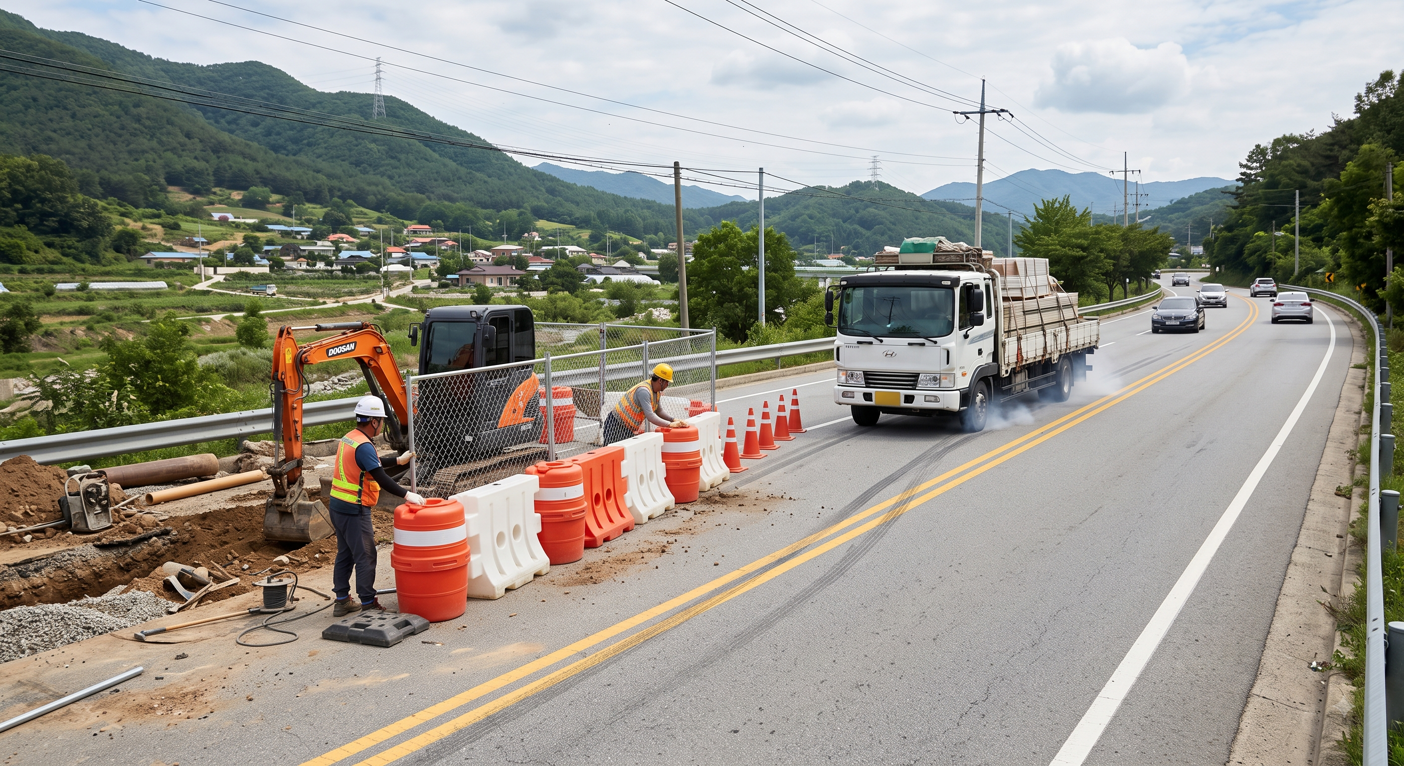
The original educational image is retained. It is not evidence of an actual incident or site suitability.
The scenario and record comparisons are fictional teaching examples, not records of real incidents, measurements, inspections, signatures or approvals.
| Item | Fictional scenario |
|---|---|
| Initial situation | Fictional example: connected water-filled units guide traffic beside an excavation. |
| Changed condition | The crew assumes the units are vehicle restraint and stores materials directly behind them. |
| Failure path | An errant vehicle can move a guidance-only unit; filling it does not establish containment performance. |
| Possible outcome | A worker or stored load may be struck inside the assumed protected zone. |
| Prevention barrier | Verify the required restraint function and exact approved system; keep the specified movement space clear. |
Failure mechanisms
Traffic guidance changes the intended path of a road user. Vehicle restraint must resist and redirect an impact within a tested and accepted system configuration. Filling a plastic unit, or giving it a familiar barrier shape, does not turn a channelizer into that system. Concrete units also depend on the specified connections and end treatment.
A system can have the correct model yet fail its intended arrangement through missing pins, an insufficient run, an exposed end or storage within its movement space. Inspect the complete installation, including interfaces at gates and access openings, rather than counting units alone.
Fence panels transfer wind load into feet, braces and anchors. Solid sheeting increases the exposed area and can alter loading. Do not fit banners, improvise ballast or change to another mesh as an emergency experiment. Use the permitted arrangement and withdraw before the assessed limit is reached.
Workers are exposed while placing and removing the protective devices themselves. Delivery order, vehicle positioning and staged traffic arrangements must leave a protected working side and an escape route. An instruction to always remove in one direction is inadequate where junctions, reversing access or a different traffic stage change the exposure.
Decision sequence
| Decision stage | What to verify |
|---|---|
| Known facts | Identify the units and the excavation exposure in the current layout. |
| Unresolved matters | The restraint acceptance and movement space have not been demonstrated. |
| Reason to hold | Do not describe or use the row as positive protection. |
| Required evidence | Obtain the road-authorised arrangement, exact system instructions and connection/end checks. |
| Restart decision | Proceed only after the selected function, installation and protected work area match the accepted plan. |
5. Conditional decisions and common errors
| Condition | Action | Evidence | Proceed when |
|---|---|---|---|
| Unknown device role | Hold the exposed task | Model and required protection | Function confirmed |
| Cover or wind change | Stop; secure from safe position | Permitted fence arrangement | Stability confirmed |
| Leak or missing pin | Isolate the affected section | Fill and connection inspection | System restored |
| Removal exposes crew | Keep traffic controls in place | Staged withdrawal and escape | Safe stage ready |
Similar situations, different decisions
The scenario and record comparisons are fictional teaching examples, not records of real incidents, measurements, inspections, signatures or approvals.
| Comparison | Situation A | Situation B |
|---|---|---|
| Appearance | Water-filled plastic units | Water-filled plastic units |
| Evidence | Guidance-only product | Accepted restraint system in its required configuration |
| Decision | Guide traffic; no assumed impact protection | Use only with verified ends, connections and clear movement space |
6. Roles and responsibilities
| Role | Responsibility |
|---|---|
| Traffic designer / authority | Defines and authorises the applicable layout, protection function and changes within their responsibilities. |
| Installation lead | Coordinates protected unloading, handling, assembly and stage transitions. |
| Product / technical reviewer | Confirms system identity, compatible components, support and installation limitations. |
| Traffic-control crew | Uses the agreed communications and escape routes; reports intrusions and layout changes. |
| Inspection / handover lead | Records defects, weather or impact reviews, maintenance and the final removal check. |
Supervision, records, handover
| Job stage | Technical and procedural controls | Site verification |
|---|---|---|
| Approve layout | 1. Confirm protection role2. Control plan revisions3. Agree public route | 1. Approved layout2. Product role3. Accessible route |
| Plan delivery | 1. Allocate protected zone2. Confirm handling method3. Brief escape route | 1. Traffic stage2. Lift and delivery plan3. Crew briefing |
| Accept installation | 1. Inspect complete system2. Check fill and braces3. Keep clearance available | 1. Pins and terminals2. Support and fill3. Movement space |
| Release operation | 1. Check signs and lamps2. Inspect pedestrian route3. Assign maintenance | 1. Approach view2. Route condition3. Maintenance owner |
| Manage changes | 1. Require technical review2. Isolate damage3. Record approved changes | 1. Weather review2. Impact inspection3. Layout revision |
| Close and withdraw | 1. Approve staged removal2. Maintain crew protection3. Inspect final road | 1. Withdrawal plan2. Final crew clearance3. Handover record |
7. Hold points and record comparison
| Hold point | Evidence before release | Confirmation / approval |
|---|---|---|
| Start | Selection checks, protected delivery, installation, inspection and removal of identified concrete barriers, water-filled units and temporary fencing beside a road work area, including pedestrian access and temporary lighting. | |
| HP-1 Protect work zone | Advance warning · Protected delivery zone · Traffic-control roles · Escape route | |
| HP-2 Connect and fill | Pins and ends · Fill and leak check · Movement clearance · Braces and covers | |
| HP-3 Inspect and hand over | Connection condition · Wind and damage review · Fill and support · Handover responsibility | |
| HP-4 Remove in stages | Protected withdrawal · Handling and support · Drainage/disposal plan · Final road check |
Complete after actual checks. Recheck after changes, defects or shift handover.
Record comparison examples
The scenario and record comparisons are fictional teaching examples, not records of real incidents, measurements, inspections, signatures or approvals.
The boxes are static record prompts, not interactive or saved approvals. A tick does not establish suitability or permission to restart. Record the evidence, person, time and unresolved issues; retain the change history.
| Record type | Insufficient record | Record checklist |
|---|---|---|
| Selection | Water barriers installed | □ Required function□ Exact product model□ Accepted configuration□ Layout revision |
| Installation | All units connected | □ Pins and terminals□ Fill and leaks□ Support and slope□ Clear movement space |
| Fencing | Extra sandbags added | □ Cover type and area□ Designed feet and braces□ Wind criteria□ Services before stakes |
| Handover | Road looks clear | □ Night visibility□ Accessible pedestrian route□ Inspection responsibility□ Protected removal sequence |
8. Site checklist and emergency response
| Check item | Result | Person / action |
|---|---|---|
| □ Select function: Device function | ||
| □ Protect work zone: Advance warning | ||
| □ Unload and handle: Unit mass | ||
| □ Prepare support: Base and slope | ||
| □ Connect and fill: Pins and ends | ||
| □ Check visibility: Signs and lamps | ||
| □ Inspect and hand over: Connection condition | ||
| □ Remove in stages: Protected withdrawal | ||
| □ Release / handover authority |
Stop work
Hold work if the traffic protection is absent, the product function is unknown, a connection or terminal is incomplete, the required deflection space is occupied, or a fence moves in wind. After impact, leakage or unauthorised relocation, isolate the affected section and obtain reassessment before relying on it.
Emergency response
Warn the traffic-control lead and withdraw along the planned escape route when a vehicle enters the work zone or a fence becomes unstable. Do not run into traffic to retrieve a fallen panel. Arrange safe traffic control before rescue or recovery, call emergency services as required, and preserve the damaged configuration for assessment.
9. Sources and review limits
2026-10-08
| Source | Scope and limitations |
|---|---|
| DfT - Safety at street works and road works | Official 2013 code and stated road exclusions; site layout still requires appropriate authorisation. |
| HSE - CIS53 | Planning protection during installation, maintenance and removal; historical statutory references not asserted as current. |
| FHWA - MUTCD, Part 6K.10 | Foreign technical distinction between guidance and restraint, not British law. |
| Heras - safety measures | Product handling and component-change example; exact supplied system instructions govern. |
This is reference content written and revised with AI. It has not been verified or approved by a professional. Review by a suitably qualified professional and site authorisation are required before use.
10. PDF guidance and FAQ
PDF A covers basic task controls; B focuses on technical failures; C covers supervision, records and handover. The article has eight stages with four items per main cell; each PDF has six key stages with three items per main cell. P/S/R/A, measurements, confirmations and signatures remain blank for actual site assessment.
Content group ID
jsa-barricade-installation
Does filling a plastic unit make it a crash barrier?
No. Establish its declared function and the acceptance of the complete restraint system. Guidance-only devices must not be treated as vehicle impact protection.
Can mesh fencing be covered for privacy?
Only after confirming the permitted wind-loading arrangement, feet, bracing and site conditions. A cover changes the loads; more improvised ballast is not proof of stability.
Should every unit be filled completely with water?
Follow the exact product fill instructions and operating conditions. Frost provisions, alternative fill or additives need manufacturer and environmental compatibility; do not assume one quantity suits all products.
Is a two-person lift always safe?
No. Assess unit mass, size, grip, posture, reach, repetition and traffic exposure. Use appropriate handling aids and the lifting points allowed for that component.
Has a professional verified or approved this document?
No. Public sources and editorial, layout and consistency checks were reviewed using AI. No site inspection or professional technical approval has been performed. Obtain appropriate professional review before use.
11. Revision history and authorship
This is reference content written and revised with AI. It has not been verified or approved by a professional. Review by a suitably qualified professional and site authorisation are required before use.
| Date | Version | Change | Review status |
|---|---|---|---|
| 2026-08-17 | Original version unmarked | Original preserved | No professional approval |
| 2026-10-08 | 1.1 | Decisions, records, JSA and PDFs revised | No professional approval |
Retained advance traffic warning, protected unloading, exclusion and lifting checks, support and connections, wind exposure, visibility, pedestrian protection and staged removal. Corrected the assumption that all filled plastic units provide vehicle restraint. Removed unsupported uniform wind, fill and team-lifting thresholds, arbitrary additives or ballast, and automatic taper-calculation claims. Preserved useful controls while replacing unverified incident/investigation narratives with an explicitly fictional scenario. This is AI reference content without professional approval. Do not apply a layout outside the code’s road scope. HSE CIS53 discusses risks to the crew setting out, maintaining and removing controls; it is technical guidance with older legislative references, not a current consolidated legal code. LOLER duties require appropriate planning and examination, not an undefined “LOLER-approved” label on all equipment. Full Chapter 8 and British Standards conformity was not audited.