This is reference content written and revised with AI. It has not been verified or approved by a professional. Review by a suitably qualified professional and site authorisation are required before use.
Revision: the master JSA is organised into eight stages with four prompts in each main cell. Short conditional release criteria and sixteen record prompts separate evidence from approval. Three six-stage PDFs use task, technical-failure and supervision viewpoints; actual evaluation fields remain blank. Valid prior explanations, sources and history are retained. This is an editorial revision, not professional technical verification.
1. Legal and technical scope
Review update, 12 October 2026: the entries below identify the official material rechecked for this revision and its specific scope. Earlier source notes and dates are retained as revision history; they do not mean that every cited provision was reverified today. Full paid standards, actual equipment manuals, site calculations and approvals were not supplied or verified. Resolve their current applicability with a qualified reviewer before use.
| Source | Scope and limitations |
|---|---|
| SafeWork NSW — Codes of practice | The current register explains the NSW approved-code duty from 1 July 2026: comply or provide equivalent or higher protection. Check the code applicable to the actual work. A JSA does not replace a required SWMS. |
| SafeWork NSW — Excavation work | NSW excavation guidance and the applicable-code reference were reviewed. The actual support design, plant setup and geotechnical evidence remain site inputs. |
A. Jurisdiction and intended use
This guide uses Australian English and the New South Wales legal framework because the source scenario is set in Sydney. It addresses H-beam excavation support comprising steel walers, struts, brackets and associated temporary restraints. Confirm the governing jurisdiction before applying it elsewhere in Australia; NSW provisions and code approval dates must not be treated as nationally uniform.
B. Current NSW legislation
The principal references are the Work Health and Safety Act 2011 and Work Health and Safety Regulation 2025. The 2025 Regulation replaced the 2017 Regulation and generally commenced on 22 August 2025; its separately commenced silica provisions do not provide a grace period for this shoring work. The current Act and Regulation were checked for the provisions relevant to this guide.
• Act sections 19, 22 and 26 address relevant PCBU, designer and installation/construction duties. Sections 27–28 address officers and workers; sections 46–49 address coordination and consultation.
• Regulation sections 34–38 address risk management; sections 78–80 address falls and fall-arrest rescue; section 81 and Schedule 3 address high risk work licensing.
• Sections 291 and 299–303 address high risk construction work and SWMS. Sections 304–306 address underground services and excavation risks, including additional trench controls.
• Sections 49–50 address airborne contaminants and monitoring. Part 4.3 applies where the legal confined space definition is met.
Work Health and Safety Act 2011 — current text
Work Health and Safety Regulation 2025 — current text
C. Approved codes and their legal status
From 1 July 2026, NSW WHS Act section 26A requires a PCBU to comply with an approved code of practice or manage the relevant hazards and risks by another method providing an equivalent or higher standard of health and safety. A code is distinct from legislation, but describing NSW approved codes as merely optional guidance would be misleading. A national model code is not automatically an approved NSW code.
Relevant NSW codes include Excavation work, Construction work, Managing the risk of falls at workplaces, Safe design of structures, Welding processes and, where applicable, Confined spaces. The NSW Elevating work platforms code commenced on 10 July 2026. Older code wording and references must be read alongside current legislation and the current NSW code register.
SafeWork NSW — approved codes and section 26A
D. JSA, SWMS, permits and licences
A JSA is a task risk-analysis tool. A SWMS has specific legal requirements when the task is high risk construction work. A permit-to-work coordinates defined activities and release conditions; a high risk work licence authorises a specified class of work. These documents and authorisations serve different purposes.
For this activity, relevant section 291 triggers may include a risk of falling more than 2 m, work in an area with moving powered mobile plant, work near specified services, or work in or near a shaft or trench deeper than 1.5 m. Identify the actual triggers; do not classify every bulk excavation as a trench solely because of its depth. Fall risks below 2 m must still be managed where injury is reasonably likely.
Section 306 separately addresses trenches at least 1.5 m deep. Its limited exception to specified collapse controls requires written geotechnical-engineer advice, including its period of application and any conditions. It is not a general exemption from risk management.
E. Standards and design documents
AS 1657:2018 concerns fixed platforms, walkways, stairways and ladders. It is not a universal specification for excavation shoring, temporary scaffolds, every edge-protection system or safety nets. Assess its relevance to the particular access installation.
The Standards Australia catalogue listed AS 1657:2018 as current when checked. Only its catalogue information and scope summary were verified; the paid full text and detailed clauses were not reviewed. The designer must identify and obtain the applicable structural, fabrication, welding, lifting and access standards, including the correct parts, editions and amendments.
Standards may acquire mandatory effect through legislation or other applicable instruments, and may also be required by the contract or design. A newly published edition does not automatically replace an edition incorporated into legislation.
AS 1657:2018 — official catalogue
SafeWork NSW — Australian Standards and other Standards
2. Scope and required inputs
A. Included work and boundaries
The installation sequence covers planning, unloading, protected access, bracket and waler installation, strut placement, connection and restraint completion, engineered preloading, verification and handover.
“H-beam” is used descriptively. Actual steel sections, grades, lengths, splice arrangements and connection details must be identified from the project documents. Do not assume all systems have the same corbels, intersecting struts, hydraulic jacks or locking devices.
Pile driving, bored piling, ground-anchor installation, major repair, alteration, de-stressing and dismantling require their own assessed methods. This guide does not authorise those operations.
B. Engineering information required before installation
• Geotechnical information covering soil and rock conditions, groundwater, adjacent foundations, services and foreseeable ground movement.
• Issued temporary works drawings and calculations identifying each construction stage, excavation limits, support levels, load paths, erection restraints and allowable surcharge zones.
• Connection schedules covering bearing details, bolt assemblies, tightening method, weld procedures, inspection requirements and acceptance criteria.
• A documented preload and lock-off procedure where preloading forms part of the design, including targets, tolerances, sequence, monitoring and safe recovery arrangements.
• A monitoring plan with baseline readings, trigger levels, responsibilities, inspection frequency and actions following movement, rainfall, impact or other changes.
• Defined design-review and verification responsibilities, including independent checking where required by the project or applicable obligations.
C. Work planning and personnel records
• A site-specific SWMS identifying the high risk construction work, hazards, controls, and how controls will be implemented, monitored and reviewed.
• A lift plan proportionate to the operation, with member weights, centres of gravity, lifting arrangements, crane configuration, ground assessment and communication arrangements.
• Current equipment manuals, relevant inspection and maintenance records, lifting-gear identification and hydraulic-system verification records.
• Applicable high risk work licences, general construction induction evidence, task competency, equipment familiarisation and employer authorisation.
• Emergency arrangements covering excavation evacuation, collapse, suspended workers, EWP recovery, fire and relevant atmospheric hazards.
D. Permit and authorisation register
Record the basis for each permit: legislation, approved code, asset-owner conditions or project procedure.
• Excavation, lifting and temporary works release authorisations as required for the site.
• Hot-work authorisation addressing ignition sources, surrounding materials, ventilation, fire response and post-work checks. Apply the NSW Welding processes code or document an equivalent or higher control method under section 26A.
• Confined space entry permits where the legal definition and entry requirements apply. Depth or restricted access alone does not determine classification.
• Service isolations and access permissions required by affected asset owners.
A permit, a low risk score or a supervisor’s signature cannot replace a required SWMS, licence, inspection, design verification or outstanding Hold Point. None authorises operation outside manufacturer limits.
3. Eight-stage JSA
| Job stage | Hazards and effects | Failure factors | Technical and procedural controls | Site verification | P | S | R | A |
|---|---|---|---|---|---|---|---|---|
| 1. Plan and ground | 1. Ground collapse2. Water or base failure3. Service strike4. Adjacent settlement | 1. Wrong ground model2. Excavation too deep3. Unknown services4. Surcharge omitted | 1. Check staged design2. Verify ground and water3. Locate and protect services4. Set monitoring triggers | 1. Design and SWMS review2. Ground and water record3. Service clearance4. Baseline and triggers | ||||
| 2. Lift and access | 1. Dropped steel2. Crane or platform overturns3. Fall from access4. Crushing by load | 1. Wrong mass or rigging2. Weak plant support3. Unreachable sling release4. Shared lifting zone | 1. Verify actual lift setup2. Provide checked plant base3. Plan protected access4. Exclude load movement zone | 1. Mass and rigging check2. Plant support assessment3. Access and rescue plan4. Signalling and exclusion | ||||
| 3. Seats and walers | 1. Falling bracket2. Waler rotation3. Weld burn or fire4. Wall connection failure | 1. Wrong bearing detail2. Early hook release3. Uncontrolled hot work4. Unapproved attachment | 1. Match seats to design2. Secure before hook release3. Apply hot-work controls4. Inspect required connections | 1. Seat and bearing check2. Erection release record3. Hot-work and fume controls4. Weld and bolt evidence | ||||
| 4. Place struts | 1. Strut rolls or slips2. Hand crushed at joint3. Fall from bare beam4. Temporary instability | 1. Missing erection restraint2. Hands in bolt holes3. No protected work position4. Wrong member or length | 1. Fit designed restraints2. Use alignment tools3. Keep off bare flanges4. Verify member and seating | 1. Member identification2. Restraint inspection3. Protected access check4. Load-transfer release | ||||
| 5. Connect and brace | 1. Member buckling2. Connection failure3. Dropped tools4. Welding fume exposure | 1. Brace has no load path2. Wrong bolt or weld3. Tools unsecured4. Poor source extraction | 1. Complete load-path details2. Apply connection procedure3. Secure tools and lower zone4. Control fumes at source | 1. Brace and reaction check2. Bolt and weld acceptance3. Tool and zone check4. Exposure-control evidence | ||||
| 6. Preload and lock | 1. Jack or plate ejects2. Hydraulic injection3. Support overload4. Load lost at lock-off | 1. Eccentric jack reaction2. Damaged pressure line3. Wrong force conversion4. Unverified retaining system | 1. Use engineered procedure2. Keep clear of release paths3. Monitor force and movement4. Verify retained load transfer | 1. Jack and gauge records2. Preload and movement log3. Lock-off acceptance4. Leak and pressure checks | ||||
| 7. Inspect and access | 1. Unaccepted support loaded2. Fall from walkway3. Added load overstresses strut4. Unresolved defect | 1. Inspection incomplete2. Missing edge protection3. Walkway load omitted4. Paint mark treated as proof | 1. Close stage defects2. Check walkway and guards3. Verify added loads by design4. Record acceptance evidence | 1. As-built support record2. Walkway and guard check3. Added-load approval basis4. Closed inspection issues | ||||
| 8. Handover and monitor | 1. Next excavation collapses2. Movement goes unnoticed3. Unsafe alteration4. Rescuer exposed | 1. Stage not released2. Monitoring unavailable3. Strut removed for access4. Rescue improvised | 1. Release next stage explicitly2. Maintain trigger response3. Control all support changes4. Use planned protected rescue | 1. Stage and limits handover2. Monitoring status3. Change-control record4. Emergency readiness |
PDF A covers basic task controls; B focuses on technical failures; C covers supervision, records and handover. The article has eight stages with four items per main cell; each PDF has six key stages with three items per main cell. P/S/R/A, measurements, confirmations and signatures remain blank for actual site assessment.
4. Fictional scenario and failure mechanisms
A. Simulation notice
The following case is a fictional simulation for training and risk assessment. It does not represent an actual accident, a government investigation or an incident involving a particular company.
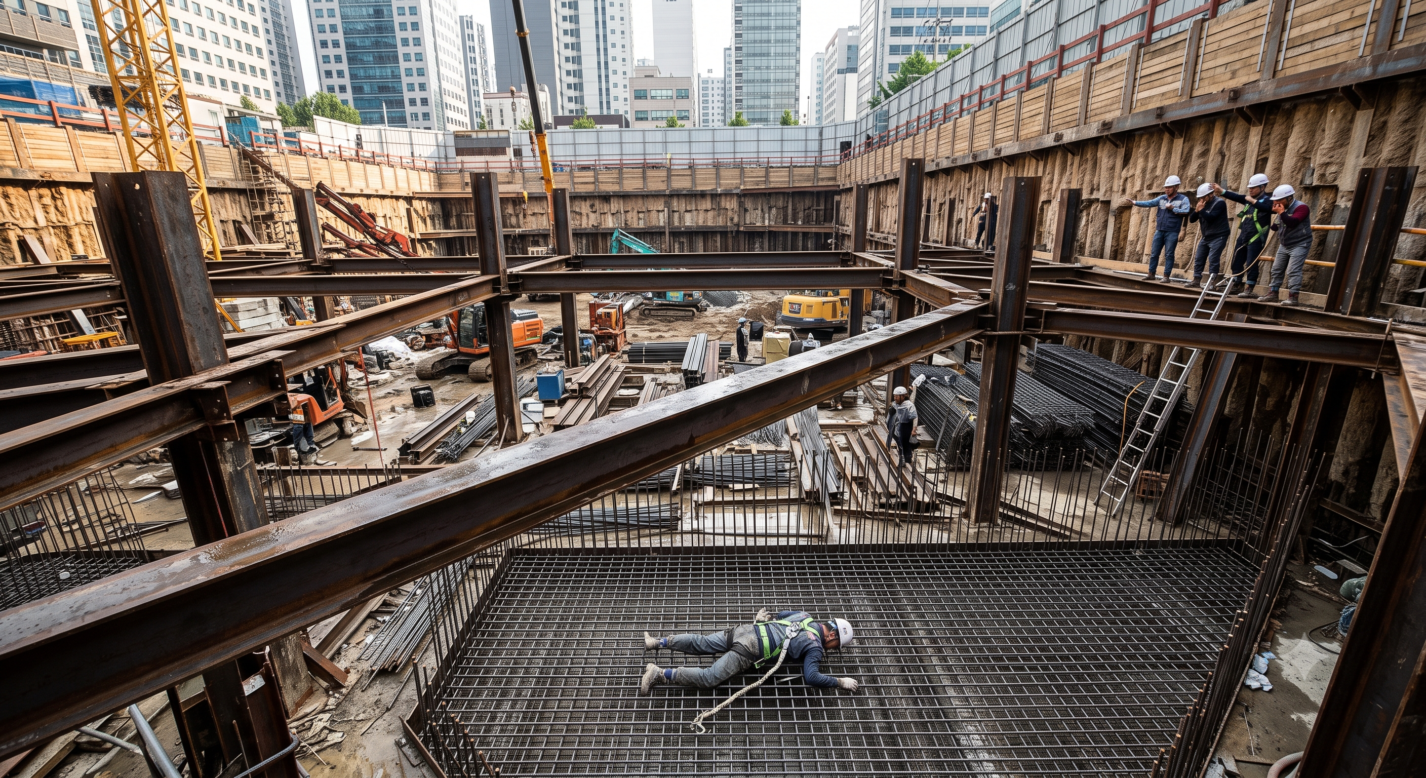
The image is retained from the source material. It is not evidence of an actual event, an accurate representation of a particular support system or an approved work method. Do not derive connection details, clearances, dimensions or safe access arrangements from it.
B. Initial conditions
In this fictional Sydney basement project, a crew is installing a third level of steel excavation struts. The selected connection position has an approximately 12 m drop to the excavation base. This distance is a scenario assumption, not a statutory threshold or a verified dimension from the image.
A crane has positioned a strut against its receiving supports. Only the erection connections identified for that intermediate stage have been fitted; the full restraint and acceptance checks have not been completed. An EWP is available, but the planned access and de-rigging sequence is bypassed.
C. Weather and work-condition changes
Overnight moisture has left the exposed steel flange slippery. The crew starts work without reassessing the wet surface and the connection position. Programme pressure encourages a shortcut before the supervisor confirms that the work position and de-rigging method are ready.
Rainfall or groundwater changes could also alter excavation conditions, but this simulation does not establish that a change in ground pressure occurred.
D. Unsafe transition and event progression
A steel erector leaves the protected work position, disconnects the fall-protection connection and steps onto the bare strut to reach the lifting gear. The member has not been released as a walkway or anchorage.
• The worker loses traction on the wet flange.
• The narrow footing provides little opportunity to recover balance.
• Inadequate restraint could permit member rotation or movement, but such movement is a possible contributor rather than an established cause.
• Without an effective fall-prevention or fall-arrest system, the worker falls to the excavation base.
• The scenario assumes fatal injuries. Falling tools or displaced steel could also injure people below.
No regulator finding, prosecution outcome or employer culpability is asserted.
E. Structural and mechanical interpretation
The following mechanisms are engineering hypotheses to support risk identification; they are not a forensic reconstruction.
• Erection stability differs from completed-system capacity. A strut designed to carry axial compression may still require temporary restraint against roll, lateral movement or loss of seating during placement.
• Off-centre actions can introduce bending and torsion. Their significance depends on member geometry, bearing, restraint stiffness and connection condition; a worker’s presence does not prove that a particular member would roll or fail.
• Buckling resistance depends on effective restraint, unsupported length, section properties, imperfections and load eccentricity. Two members crossing in plan do not automatically brace each other.
• Gaps, inadequate bearing or eccentric jack contact can change the intended load path through struts, walers, brackets and retaining elements.
• A pressurised jacking arrangement stores hydraulic and elastic strain energy. Failure can convert that energy into rapid movement; describing the stationary system as storing “kinetic energy” is inaccurate.
No numerical force, capacity, buckling load or failure sequence can be established without the actual drawings, material information, calculations and installation records.
F. Failed protective barriers
| Protective barrier | Assumed failure in the simulation | Consequence | Required recovery or prevention |
|---|---|---|---|
| Safe access and task planning |
| Worker enters an exposed position over the excavation. |
|
| Erection-stage verification |
| The worker relies on unverified support and stability. |
|
| Fall protection |
| A slip develops into an uncontrolled fall. |
|
| Change assessment |
| Slip likelihood increases. |
|
| Supervision and release |
| Several controls fail together. |
|
| Emergency readiness |
| Rescue delay or secondary casualties become possible. |
|
G. Key lessons
A steel strut is a structural component, not an access route. A harness worn without a suitable connected system does not provide fall protection. Crane support, partial bolting and a visually level member do not establish a safe work platform. Installation planning must address both structural stability and the worker’s complete access and recovery route.
5. Conditional decisions and common errors
| Condition | Action | Evidence | Proceed when |
|---|---|---|---|
| Rain or seepage changes | Hold the affected excavation; assess drainage and support response. | Water observations, movement trends and engineering disposition. | Water and support conditions accepted. |
| Rigging point unreachable | Stop unhooking; revise the protected access and lifting arrangement. | Access reach check, support assessment and lifting-team briefing. | Protected access and stable seating confirmed. |
| Unexpected preload response | Keep people clear; obtain the engineered response without uncontrolled unloading. | Force/movement log, equipment checks and revised load-transfer instruction. | Cause resolved; load retention accepted. |
| Next excavation stage | Close support defects and check monitoring before releasing the next cut. | As-built acceptance, stage drawing and current monitoring. | Required support accepted; monitoring active. |
A. Excavation and temporary works stability
The temporary works designer must define the support sequence and the conditions under which each excavation stage can proceed. Confirm groundwater management, nearby foundations, traffic and plant surcharge, stored materials and access loads.
Construction-stage checks
• Verify bearing, member orientation, connection condition, lateral restraint and the complete load path.
• Do not weld, drill, cut, substitute fasteners or attach other systems without the required design review.
• Do not excavate below the released level or undermine supports.
• Use design-specific movement and water-level triggers. An acceptable visual appearance does not establish stability.
These project controls should be developed with the NSW Excavation work code and Safe design of structures code.
B. Lifting, slinging and crane-load release
Select the lifting arrangement for the actual member, mass, centre of gravity, lifting points, sling angles and contact surfaces. Apply relevant working-load limits and configuration reductions. Double-choker hitches are not a universal requirement and may be unsuitable for a particular lift.
Crane-load release must follow the engineered erection method. Fully welded corbels are not a universal prerequisite where the design uses another connection system; equally, unverified tack welds or an arbitrary number of bolts are not an acceptable substitute for the specified release condition.
Exclusion areas must cover credible load swing, drop, rotation, plant movement and trapping hazards. No universal radius is assigned.
NSW Government — Dogging and Rigging Guide
C. Falls, access and EWPs
First consider completing work on the ground or solid construction. Where the fall risk cannot be eliminated, apply the prescribed hierarchy of fall-prevention devices, work-positioning systems and fall-arrest systems.
Choose access suited to the location. For EWPs, check ground support, operating envelope, overhead obstacles, entrapment, equipment condition and model-specific instructions. Do not assume an EWP can safely stand beside every excavation or reach every connection.
Where fall arrest is selected, verify the entire system, anchorage design, clearance, compatibility and tested rescue procedure. “100% tie-off” alone does not establish adequacy.
NSW falls code
NSW Elevating work platforms code
D. Preloading and hydraulic stored energy
Preloading is permitted only where included in the design and supported by an equipment-specific procedure. The procedure must resolve:
• Target force, permitted variation, loading order, increments and any hold periods.
• Jack position, reaction surfaces, alignment, restraint, stroke and equipment ratings.
• The verified relationship between indicated pressure and jack output, and how the required installed force will be assessed.
• Measurements of movement, bearing, connection response and other specified acceptance indicators.
• Lock-off, load transfer and controlled depressurisation, including what happens if the operation is interrupted.
Jack output and residual strut force after lock-off are not necessarily identical. Gauge readings, paint witness marks or level readings cannot independently prove structural integrity.
Keep people outside credible ejection and movement paths. Do not search for pressurised leaks with hands, loosen live connections, hammer loaded components or improvise packing and secondary jacks. Stop for unexpected movement, pressure loss, leakage, excessive stroke or abnormal structural response. Recovery requires the designer’s and equipment supplier’s applicable instructions.
E. Connections and intersections
Use the specified bolt assemblies, tightening procedure, weld details, workmanship criteria and inspection regime. Do not insert a generic torque, bolt grade or weld size into this guide.
Fit intersection restraints only where their structural function and connection details are established by design. A clamp, U-bolt or stiffener does not provide effective bracing unless its attachment and supporting structure can resist the required actions. Do not add field welds as an assumed improvement.
F. Welding, atmosphere and hot work
Consider avoiding site welding through the approved design and fabrication method. Where welding remains necessary, control fumes at source, protect nearby workers and select additional respiratory protection for the actual contaminants and exposure. Tight-fitting respirators require appropriate fit testing; particulate filters do not resolve oxygen deficiency.
Assess fire spread, concealed combustibles, electrical conditions and shielding-gas accumulation. Specify fire-watch coverage and post-work checks in the authorised procedure rather than applying an invented universal duration.
Do not classify an excavation as a confined space solely because it is deep. Where it meets the legal definition, implement the entry permit, isolation, atmosphere, standby and rescue requirements. Air monitoring is required when the conditions in Regulation section 50 are met.
SafeWork NSW — welding fumes
Welding processes code
Confined spaces code
G. Weather and measurable operating limits
Record the actual limits for the crane, EWP, lifting arrangement and temporary works stage. Wind restrictions may differ between lifting, platform use, installation and the completed structure. A structural design wind action is not an equipment operating wind limit.
For directly comparable limits, apply the most restrictive applicable condition. Do not compare values serving different purposes or measured under different conditions without competent assessment. A permit cannot authorise exceeding a manufacturer’s limit.
H. Inspection and emergency response
Check the works at the intervals and stages established by the design and site assessment, and after relevant events such as heavy rain, impact, flooding, abnormal movement or interrupted installation. Preserve safe access and emergency routes throughout.
Plan for excavation evacuation, fall arrest rescue, EWP recovery, fire and collapse. Use the model-specific recovery method; do not invent emergency-lowering or structural-release actions. Do not send rescuers into an unstable excavation or hazardous atmosphere without the necessary controls.
6. Roles and responsibilities
A. PCBU and principal contractor
Provide the resources, competent personnel, coordination and supervision needed for safe work. Where a principal contractor is required, integrate the activity with the project WHS management plan and other trades. Assigning tasks does not transfer statutory duties.
B. Temporary works designer and geotechnical adviser
Define the design basis, construction stages, connections, restraints, preload requirements and monitoring criteria. Review deviations within the scope of their appointment. Confirm qualifications, experience, any legally required professional registration and authority for the particular engineering work.
The label “engineer” does not establish that a person reviewed this installation. Record the actual scope and evidence of review.
C. Installation supervisor and temporary works coordinator
Coordinate the sequence, current drawings, workforce briefing, inspection records and Hold Point releases. A temporary works coordinator is a project role unless another applicable instrument provides otherwise; appointment alone does not confer engineering competence or statutory approval authority.
D. Crane operator, dogger and rigger
Verify the licence classes required for the actual work. Dogging includes relevant slinging judgement and directing movement when a load is outside the operator’s view. Structural placement and securing work may require a rigging class, not merely a dogging licence.
Basic rigging includes structural steel erection within its scope; additional activities may require higher classes. Check licence validity, conditions, recognised interstate authorisations and any relied-upon statutory exception.
SafeWork NSW — high risk work licences
E. Access operators, welders and inspectors
Confirm equipment and task competence separately from construction induction. Check the relevant EWP licence requirement against the equipment; not every EWP requires the same high risk work licence. Welding qualifications and inspection competence must match the work and design specification.
Training completion, licence possession, medical fitness where relevant, employer authorisation and professional registration are separate matters. None automatically establishes the others.
F. Permit issuer, workers and emergency personnel
The permit issuer verifies the stated release evidence and concurrent-work conditions. Workers follow the SWMS and report changes or defects. Emergency personnel must understand the actual equipment, access constraints and rescue plan. No person should sign for an inspection or review they did not perform or have authority to accept.
Supervision, records, handover
| Job stage | Technical and procedural controls | Site verification |
|---|---|---|
| Plan ownership | 1. Verify assigned authority2. Check staged design3. Set monitoring triggers | 1. Design and SWMS review2. Ground and water record3. Service clearance |
| Team and equipment | 1. Record equipment evidence2. Verify actual lift setup3. Exclude load movement zone | 1. Mass and rigging check2. Plant support assessment3. Access and rescue plan |
| Stage release | 1. Hold stage release2. Fit designed restraints3. Verify member and seating | 1. Member identification2. Restraint inspection3. Protected access check |
| Energy control | 1. Record energy controls2. Use engineered procedure3. Verify retained load transfer | 1. Jack and gauge records2. Preload and movement log3. Lock-off acceptance |
| Inspection closure | 1. Close inspection defects2. Close stage defects3. Record acceptance evidence | 1. As-built support record2. Walkway and guard check3. Added-load approval basis |
| Shift handover | 1. Transmit limits and issues2. Release next stage explicitly3. Use planned protected rescue | 1. Stage and limits handover2. Monitoring status3. Change-control record |
7. Hold points and record comparison
A. Permit identity and validity
Record the site, excavation zone, support level, member identifiers, work scope, permit number, validity period, linked SWMS and drawing revisions, concurrent activities, isolations and named authorising personnel.
The following Hold Points are a proposed project control framework. They are not presented as a nationally prescribed permit form. The appointed project team must allocate competent release authorities before work begins.
| Hold Point | Activity withheld | Required release evidence | Release responsibility to be appointed |
|---|---|---|---|
| HP1 — Design readiness | Installation or excavation dependent on the proposed support stage |
| Responsible designer and project authority within their documented scopes |
| HP2 — Site and plant readiness | Plant setup, delivery unloading or entry into the controlled work area |
| Site supervisor with relevant plant and ground-assessment input |
| HP3 — Access readiness | Work at connection and de-rigging positions |
| Supervisor and competent access or fall-protection personnel |
| HP4 — Member release | Transfer of crane load and disconnection of lifting gear |
| Nominated competent erection authority with the lifting team |
| HP5 — Preload readiness | Hydraulic pressurisation or other designed preload application |
| Designer’s nominated technical release authority and supervisor |
| HP6 — Preload and lock-off acceptance | Removal of temporary jacking equipment where specified, or progression dependent on preload |
| Nominated technical authority |
| HP7 — Installation handover | Use by subsequent trades or loading of completed access facilities |
| Project handover authority with relevant technical acceptance |
| HP8 — Next-stage release | Further excavation or changes affecting support demand |
| Nominated temporary works and excavation release authorities |
B. Suspension and revalidation
Suspend the affected permit when conditions, design, equipment, personnel responsibilities or work scope change in a way that affects its controls. Record the reason, immediate protective action, review and new release.
A release applies only to its defined stage and conditions. It does not approve later excavation, additional loads, structural alterations or dismantling.
C. Separate statutory permits
Where confined space entry is involved, comply with the specific written permit requirements in Regulation section 67. A general excavation or hot-work permit does not automatically satisfy those requirements.
Record comparison examples
The scenario and record comparisons are fictional teaching examples, not records of real incidents, measurements, inspections, signatures or approvals.
The boxes are static record prompts, not interactive or saved approvals. A tick does not establish suitability or permission to restart. Record the evidence, person, time and unresolved issues; retain the change history.
| Record type | Insufficient record | Record checklist |
|---|---|---|
| Plan and ground | “OK” | □ Design and SWMS review□ Ground and water record□ Service clearance□ Baseline and triggers |
| Place struts | “OK” | □ Member identification□ Restraint inspection□ Protected access check□ Load-transfer release |
| Preload and lock | “OK” | □ Jack and gauge records□ Preload and movement log□ Lock-off acceptance□ Leak and pressure checks |
| Handover and monitor | “OK” | □ Stage and limits handover□ Monitoring status□ Change-control record□ Emergency readiness |
8. Site checklist and emergency response
A. Documents and briefing
• ☐ Correct jurisdiction, work location, support stage and document revisions confirmed.
• ☐ Site SWMS identifies the applicable high risk construction work and is understood by the crew.
• ☐ Required licences, task competence and delegated responsibilities checked.
• ☐ Design queries closed and applicable Hold Points released.
B. Ground, water and surroundings
• ☐ Excavation condition and monitoring readings are acceptable for this stage.
• ☐ Adjacent structures, services and surcharge restrictions are addressed.
• ☐ Plant standing areas and travel routes remain suitable after weather or site changes.
• ☐ Water-control arrangements operate as designed and escape routes remain usable.
C. Steel and lifting
• ☐ Member identities, masses, lifting points and centres of gravity are confirmed.
• ☐ Steel, lifting gear, receiving seats and temporary restraints are free of unacceptable defects.
• ☐ Crane configuration, load path, signalling and exclusion areas match the plan.
• ☐ De-rigging can be completed without walking on bare steel.
D. Access and fall controls
• ☐ Platforms, scaffold or EWPs suit the connection positions and supporting conditions.
• ☐ Edge protection and openings are controlled before exposure occurs.
• ☐ Any required personal fall system has verified anchorage, compatibility and clearance.
• ☐ Applicable rescue arrangements are ready and understood.
E. Connections and hydraulics
• ☐ Prerequisite bolts, welds and restraints are accepted before load application.
• ☐ Jack, pump, hose and gauge identities match the approved procedure.
• ☐ Preload targets, equipment limits, movement triggers and stop conditions are available.
• ☐ Lock-off and controlled load-transfer arrangements are verified.
F. Hot work and atmosphere
• ☐ Hot-work authorisation and concurrent-work controls are in place where required.
• ☐ Fume control, ventilation and any required RPE are suitable.
• ☐ Confined space applicability has been assessed; applicable permits and controls are complete.
• ☐ Fire response, monitoring and post-work inspection arrangements are assigned.
G. Final readiness
• ☐ Weather conditions remain within the applicable operational limits.
• ☐ Workers know the stop signal, evacuation route and emergency contacts.
• ☐ No critical item is left unresolved or marked “not applicable” without justification.
• ☐ The authorising person has recorded the release scope and time.
Retain evidence, corrective actions and responsible persons with the completed checklist. Ticking a box without verification does not release the work.
9. Sources and review limits
Review update, 12 October 2026: the entries below identify the official material rechecked for this revision and its specific scope. Earlier source notes and dates are retained as revision history; they do not mean that every cited provision was reverified today. Full paid standards, actual equipment manuals, site calculations and approvals were not supplied or verified. Resolve their current applicability with a qualified reviewer before use.
| Source | Scope and limitations |
|---|---|
| SafeWork NSW — Codes of practice | The current register explains the NSW approved-code duty from 1 July 2026: comply or provide equivalent or higher protection. Check the code applicable to the actual work. A JSA does not replace a required SWMS. |
| SafeWork NSW — Excavation work | NSW excavation guidance and the applicable-code reference were reviewed. The actual support design, plant setup and geotechnical evidence remain site inputs. |
A. Legislation and commencement
• NSW Work Health and Safety Act 2011 — relevant duties, consultation and section 26A. The current version displayed when checked commenced on 1 July 2026.
• NSW Work Health and Safety Regulation 2025 — falls, licensing, SWMS, excavation, contaminants and confined spaces. The current compilation identified when checked was dated 3 July 2026.
• SafeWork NSW legislation and commencement information — replacement of the 2017 Regulation and staged commencement information.
• SafeWork NSW approved code register — NSW approval status and the section 26A duty.
B. Official technical and operational guidance
• Excavation work code — planning, ground support, plant, access and inspection; listed by NSW as January 2020.
• Construction work code — construction planning and SWMS; listed as August 2019.
• Safe design of structures code — design risk management and communication; listed as August 2019.
• Managing the risk of falls at workplaces code — fall-control selection and access; listed as August 2019.
• Elevating work platforms code — NSW code commencing 10 July 2026.
• Welding processes code — welding hazards and hot-work procedures; listed as December 2022.
• Confined spaces code — classification, entry controls and rescue; listed as December 2022.
• SafeWork NSW welding-fume guidance — exposure assessment and current control guidance.
• NSW Government Dogging and Rigging Guide — practical lifting and rigging guidance; it is not itself a project lift plan or a substitute for licensing requirements.
C. Standards verification boundary
• Standards Australia — AS 1657:2018 — official catalogue title, current status and scope summary checked. Full-text compliance was not assessed.
• SafeWork NSW — standards and WHS obligations — distinction between standards, approved codes and legal obligations.
A code’s issue date, a law’s commencement date, a compilation date and a webpage update date describe different things. Older codes may retain earlier regulation references. Do not rely on filenames or website update dates as proof of legal currency.
D. Applying the references
• Establish the applicable legislation, legally incorporated documents, approvals and enforceable conditions.
• Apply relevant NSW approved codes or substantiate an equivalent or higher method as permitted by section 26A.
• Reconcile the project design, applicable standards, equipment instructions and operating limits. Stop and resolve any conflict through competent review.
• Implement the resulting requirements through the site SWMS, permits, inspections and stage releases.
These references are complementary. A project document cannot relax legislation, and a generic code example cannot replace a design for the actual support system. Apply the most restrictive compatible requirement when comparing limits for the same function; do not rank unrelated numerical values.
10. PDF guidance and FAQ
PDF A covers basic task controls; B focuses on technical failures; C covers supervision, records and handover. The article has eight stages with four items per main cell; each PDF has six key stages with three items per main cell. P/S/R/A, measurements, confirmations and signatures remain blank for actual site assessment.
The three PDF sheets are complementary extracts, not a complete work sequence. Apply all eight body stages and the applicable site procedure. PDF HP-0 to HP-4 are worksheet labels: match each to its event, evidence and responsible authority, not to the same number in a different permit or table. An omitted PDF stage is not permission to omit its controls.
A. Proposed record structure
The fields below are proposed inputs and workflow requirements. Their inclusion does not confirm that these features are currently implemented in Smart JSA Bridge.
• Country AU, language en-AU, governing jurisdiction, regulator and legal-check date.
• Project, excavation zone, support level, member identifiers and current construction stage.
• Design references, revisions, review status, responsible designer and delegated release authorities.
• Applicable high risk construction work categories, SWMS reference and worker consultation record.
• Crane, EWP and hydraulic equipment identities, relevant manuals and verified limitations.
• Required licence classes, competence records and task authorisations.
• Connection inspection results, preload records, monitoring readings and outstanding defects.
• Permit identity, Hold Point evidence, reviewer signatures and release conditions.
B. Suggested workflow checks
Subject to implementation and validation, the platform could flag or withhold a proposed document release where:
• The jurisdiction or current design revision is missing.
• Applicable SWMS, licence or permit information is unresolved.
• Required connection, restraint, access or preload evidence is incomplete.
• A monitoring trigger has been reached or a safety-critical defect remains open.
• The proposed activity exceeds a recorded equipment limit or an unreleased stage.
These are proposed document-workflow checks, not verified physical interlocks. They cannot establish that site conditions are safe, stop machinery, verify a signature’s authenticity or replace a responsible person’s inspection.
C. Risk assessment and change control
Keep P, S, R and A blank until the authorised site assessment is completed. Preserve the source of each technical limit and distinguish manufacturer data, design values, legal requirements and site decisions.
A changed drawing, member, access arrangement or preload procedure should prompt review of affected work stages and Hold Points. Automated drafting must not create engineering approval or acceptance records.
D. Responsible platform use
Smart JSA Bridge may be used as the destination for organising the proposed job steps and reviewed records, subject to its actual available functionality. No claim is made here that the platform calculates safe shoring capacity, certifies designs, verifies legal compliance or provides real-time site protection.
Does an H-beam shoring JSA replace a SWMS in NSW?
No. Where the work is high risk construction work, a site-specific SWMS meeting the applicable NSW requirements must be prepared before work starts. A JSA can support that process, but this generic guide is not a completed site SWMS.
Must an EWP be used for every waler and strut connection?
No single access method suits every location. Apply the fall-control hierarchy and select suitable protected access, such as an engineered platform, scaffold or EWP. Consider ground capacity, reach, entrapment, rescue and equipment limitations. Do not use bare struts as access routes.
Are double-choker hitches mandatory for lifting H-beams?
There is no blanket requirement in this guide to use double-choker hitches. The lifting arrangement must suit the member, load mass, centre of gravity, lifting points, sling ratings and manufacturer instructions, with the required licensed dogging or rigging personnel.
What pressure should be used to preload an excavation strut?
Use the project-specific preload, sequence and acceptance criteria specified by the temporary works designer, together with the relevant hydraulic equipment instructions. There is no universal jack-pressure setting. A pressure gauge alone does not verify the installed strut force or structural stability.
Does every deep excavation require a confined space entry permit?
Depth alone does not determine whether an excavation is a confined space. Assess the actual space against the legal definition. Where confined space requirements apply, the required entry permit and associated controls must be in place. Other excavation, lifting and hot-work authorisations must also be assessed separately.
Has a professional verified or approved this document?
No. Public sources and editorial, layout and consistency checks were reviewed using AI. No site inspection or professional technical approval has been performed. Obtain appropriate professional review before use.
11. Revision history and authorship
A. Origin and status
This document is a technical draft generated through Smart JSA Bridge’s automated engineering-content workflow. It is prepared as publication content and as a starting point for site-specific review. It is not an issued-for-construction design, a completed site SWMS or a work authorisation.
B. No implied professional or government approval
Unless a verifiable signature and review record are attached, this document has not been authored, reviewed or approved by an actual engineer, safety professional, equipment manufacturer or government authority. Linking official sources does not imply endorsement by those organisations.
C. No physical inspection
The system has not physically inspected the equipment, steelwork, connections, excavation, neighbouring structures, ground, groundwater or actual working conditions. It has not verified member dimensions, installed loads, workmanship or the effectiveness of site controls.
D. Documents this draft does not replace
This draft does not replace legal advice, manufacturer procedures, structural calculations, statutory inspection records, evidence of qualifications or licences, site risk assessment, a required SWMS, permit conditions or work approval.
Before actual use, appropriately qualified, competent and authorised people for the jurisdiction and site must review the content, resolve outstanding information and approve the applicable work documents within their respective scopes.
E. Limits of verification
Official sources identified in this guide were consulted for the stated legal and general technical matters. No project calculations, geotechnical report, equipment-specific manual, actual inspection record or signed professional review was supplied. Paid technical-standard clauses were not verified. Proposed integration fields and blocking rules must not be represented as implemented platform capabilities without separate confirmation.
F. Actual professional review record
Any review actually performed must be recorded separately with the following information:
• Reviewer’s name and organisation.
• Qualifications and formal delegation of authority.
• Scope of review.
• Equipment and documents reviewed.
• Review date and signature.
• Limitations and exclusions.
• Required amendments.
• Conditions under which approval remains valid.
No professional review or approval record is asserted by this publication.
Legal and source verification date: 19 September 2026. Recheck legislative currency, code approval status, applicable standards, manufacturer instructions and site conditions before use, and whenever the work or governing requirements change.
2026-10-12 · v2026.10.12
Revision: the master JSA is organised into eight stages with four prompts in each main cell. Short conditional release criteria and sixteen record prompts separate evidence from approval. Three six-stage PDFs use task, technical-failure and supervision viewpoints; actual evaluation fields remain blank. Valid prior explanations, sources and history are retained. This is an editorial revision, not professional technical verification.
This is reference content written and revised with AI. It has not been verified or approved by a professional. Review by a suitably qualified professional and site authorisation are required before use.