Australian construction planning. A site planning reference for temporary distribution boards, protected cable routes and staged electrical verification. Retain secure mounting, safe isolation, specified terminal torque and damage checks; decide whether each circuit may proceed using traceable evidence.
Prove isolation, verify the protective path, then release testing in stages
This is reference content written and revised with AI. It has not been verified or approved by a professional. Review by a suitably qualified professional and site authorisation are required before use.
Stop work
Stop when isolation is uncertain, protective continuity is unverified, water or cable damage is found, test results fail, or a device trips without a diagnosed cause. Keep the affected circuit isolated and labelled until corrective work, retesting and authorised release are complete.
1. Legal and technical scope
| Basis | Application limits |
|---|---|
| Safe Work Australia: electrical safety | Model WHS responsibilities and referral to state/territory regulators reviewed; not a national licence or approval. |
| Model Code: Managing electrical risks | Official publication page and stated jurisdiction-dependent legal effect reviewed; no claim of reviewing all linked editions. |
| SWA construction electrical-safety duties | Official construction guidance on competence and risk planning reviewed in the published/indexed scope. |
Australia: confirm the state or territory electrical-safety and WHS regime, licence requirements and adopted standards. Safe Work Australia publishes model guidance and is not the regulator. This reference is not, by itself, a completed site SWMS.
The original AS/NZS titles are retained as identifiers; their full texts and every local adoption were not verified. Confirm whether high-risk construction work requires a SWMS. Determine the actual MEN or other supply arrangement and generator configuration before bonding; a local electrode is not a replacement for the protective conductor. Select RCD type and inspection/test intervals under the applicable rules and instructions.
2. Scope and required inputs
Included scope
Low-voltage temporary supplies installed and tested by appropriately qualified and authorised electrical workers. Identify every utility, generator, UPS, battery and possible backfeed before work.
Separate review
This plan does not authorise live installation, high-voltage work, explosive-atmosphere work or work near overhead utility lines. These require separate competent design, procedures and permissions. Cable support work at height also needs its own access controls.
| Required input | What to verify |
|---|---|
| Supply | Jurisdiction, nominal voltage, source identity, earthing arrangement, fault level and means of isolation. |
| Load and route | Cable sizing and voltage drop, protective-device coordination, vehicle envelope, support capacity, water and impact exposure. |
| Test plan | Device model, manual revision, test configuration and limits, instrument identity, competent tester and release authority. |
Confirm the applicable edition and local adoption of each standard before use. Full paid standards and actual equipment manuals were not reviewed. No universal electrode resistance, clearance, ingress rating, insulation test voltage or trip-time limit is prescribed here. Record the actual acceptance criterion and its source before testing.
3. Eight-stage JSA
| Job stage | Hazards and effects | Failure factors | Technical and procedural controls | Site verification | P | S | R | A |
|---|---|---|---|---|---|---|---|---|
| 1. Plan supply | 1. Backfeed2. Excess load3. Wrong protection4. Unknown fault level | 1. Sources not traced2. Loads not listed3. Device mismatched4. No earthing design | 1. Map every source2. Size cable and protection3. Select earthing system4. Assign qualified staff | 1. Source drawing2. Load schedule3. Protection settings4. Named duty holder | ||||
| 2. Isolate | 1. Electric shock2. Stored charge3. Unexpected restart4. Adjacent live parts | 1. Wrong isolator2. Remote start enabled3. Tester not proved4. Neutral overlooked | 1. Lock all sources off2. Disable auto restart3. Prove dead by contact4. Guard adjacent live parts | 1. Lock identifiers2. Tester before/after3. All conductors checked4. Discharge verified | ||||
| 3. Mount and bond | 1. Cabinet overturn2. Water ingress3. Touch voltage4. Access blocked | 1. Stand unsecured2. Glands unsuitable3. PE path broken4. Rod treated as PE | 1. Anchor stable stand2. Fit rated glands3. Bond PE to design4. Keep isolator accessible | 1. Stand and drainage2. Covers secured3. PE continuity4. Earthing arrangement | ||||
| 4. Route and wire | 1. Vehicle crush2. Sharp edge damage3. Loose hot terminal4. Coupler water ingress | 1. Route not protected2. Excess pulling force3. Torque guessed4. Tape-only repair | 1. Guard vehicle crossing2. Support without strain3. Use specified torque4. Remove damaged leads | 1. Route clearance2. Cable identification3. Torque record4. Coupler and seal | ||||
| 5. Dead tests | 1. Test voltage shock2. Electronics damaged3. False pass4. Retained test charge | 1. Loads still connected2. Wrong test voltage3. PE not tested4. Result copied | 1. Secure test boundary2. Isolate sensitive loads3. Test PE, polarity, IR4. Discharge and recheck | 1. Test configuration2. Instrument identity3. Actual test readings4. Defects closed | ||||
| 6. Live tests | 1. Arc flash2. Unexpected start3. Protection failure4. Contact with voltage | 1. Dead tests incomplete2. People in test zone3. Wrong device test4. Test button only | 1. Release test hold point2. Use qualified tester3. Control energisation4. Test specified protection | 1. Dead-test review2. Device and test mode3. Trip result record4. Covers restored | ||||
| 7. Use and faults | 1. Wet damaged cable2. Repeated fault3. Overloaded lead4. Unauthorised opening | 1. Flood damage ignored2. Blind breaker reset3. New load not reviewed4. Door left open | 1. Check before use2. Isolate any defect3. Review load changes4. Retest after repair | 1. Route condition2. Fault diagnosis3. Retest evidence4. Restart authorisation | ||||
| 8. Handover | 1. Hidden change2. Unknown live cable3. Unsafe dismantling4. Open defect handed on | 1. Drawing outdated2. No circuit labels3. Disconnect under load4. Records missing | 1. Update circuit register2. Brief incoming team3. Isolate before removal4. Close or isolate defects | 1. As-built drawing2. Receiving person3. Isolation for removal4. Approval and date |
PDF A covers basic task controls; B focuses on technical failures; C covers supervision, records and handover. The article has eight stages with four items per main cell; each PDF has six key stages with three items per main cell. P/S/R/A, measurements, confirmations and signatures remain blank for actual site assessment.
4. Fictional scenario and failure mechanisms
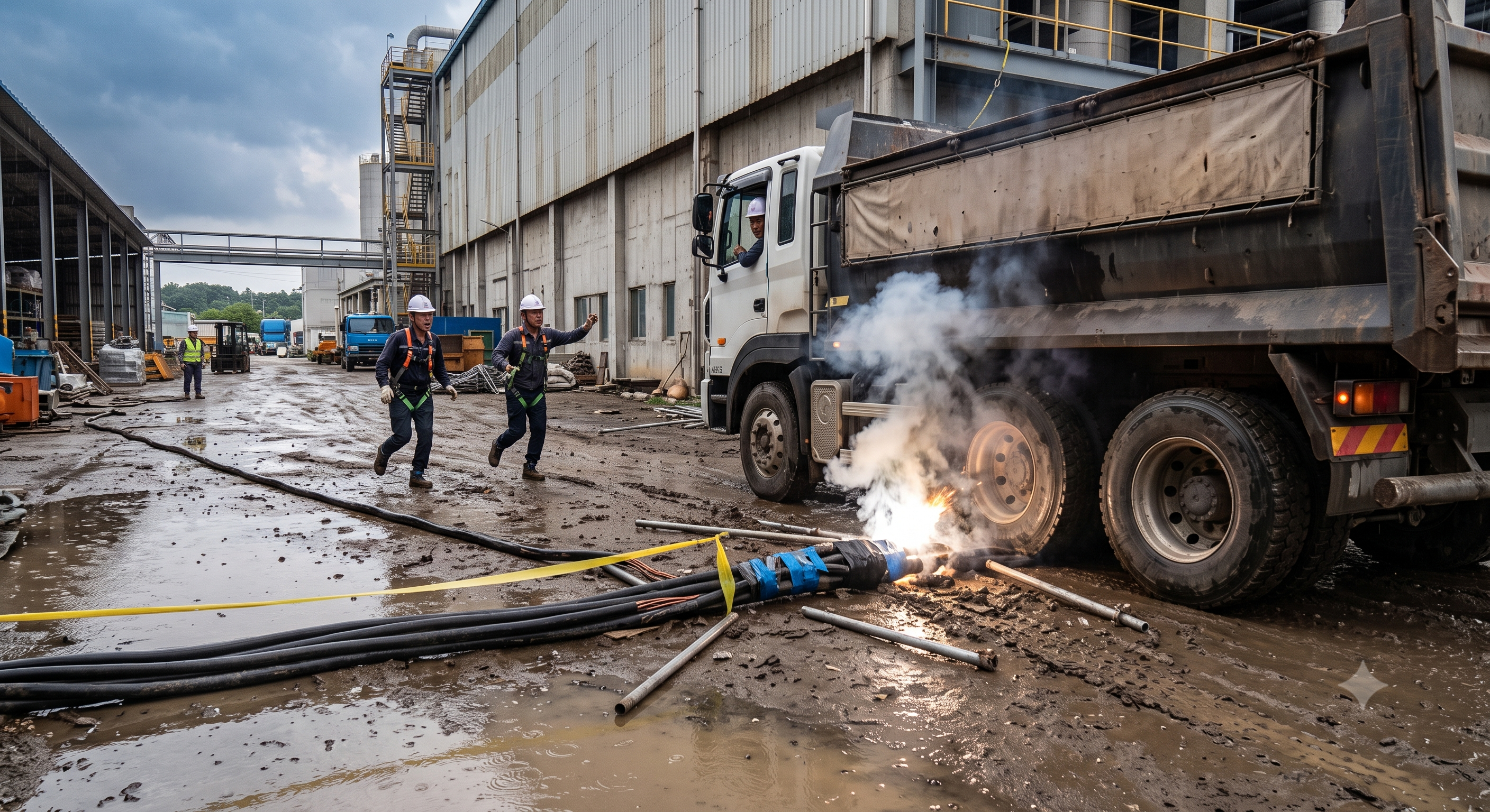
The original educational image is retained. It is not evidence of an actual incident or site suitability.
The scenario and record comparisons are fictional teaching examples, not records of real incidents, measurements, inspections, signatures or approvals.
| Item | Fictional scenario |
|---|---|
| Initial situation | A temporary feeder crosses a vehicle route during a short job. |
| Changed condition | A damaged sheath is taped, the route is unguarded and rain collects at the crossing. |
| Failure path | Wheel loading may damage insulation; moisture may establish a fault path. |
| Immediate response | Stop traffic and use, isolate safely, keep people away and have the cable assessed or replaced. |
| Release condition | Resume only after route protection, electrical retesting and documented site release. No measured fault time, injury outcome or financial loss is claimed. |
Failure mechanisms
A protective conductor and bonding arrangement maintain the designed fault path. An electrode reading alone does not prove PE continuity or automatic disconnection; a rod must not replace the circuit protective conductor. Neutral-to-earth bonding depends on the supply design, including generators.
A suitable contact voltage detector must be proved before and after checking all relevant conductors at the work location. A non-contact indication, open switch or stopped machine alone does not establish a safe isolated state. Control stored energy, possible recharging and adjacent live parts.
An RCD/GFCI supplements the specified protective arrangement; its test button does not establish every installation condition or substitute for required instrument tests. Device class, residual-current waveform, settings, test current and permitted disconnection time must match the circuit and manual.
Insulation testing introduces hazardous voltage: segregate the test area, disconnect sensitive loads as specified, select a compatible test method, discharge and verify afterwards. Loose terminals can overheat; paint marks do not prove torque. Arc incident energy cannot be determined by a simple voltage × current × time expression.
Use enclosure-compatible glands and blanking fittings; generic putty must not be assumed to preserve ingress protection or ventilation. NEMA and IP ratings are not interchangeable labels. Confirm cable supports, sag and actual vehicle clearance, including raised equipment, under an approved route plan. Select test leads, instrument category, insulating tools and shock/arc PPE for the task and available energy; no single glove or PPE rating applies to all work. Temporary earthing/short-circuiting, where required for re-energisation or induction risks, must follow a competent procedure after proving dead. Record test and inspection intervals from the applicable local rules, risk assessment and manufacturer; a coloured label is not evidence by itself.
Decision sequence
| Decision stage | What to verify |
|---|---|
| Identify | The electrical lead identifies the affected source and circuit. |
| Hold | Suspend use for damage, water ingress, unexplained trips or uncertain isolation. |
| Correct | The qualified worker corrects the defect under controlled isolation. |
| Verify | Review actual test results, protection settings, route condition and remaining defects. |
| Release | Only the designated site authority releases the defined circuit and records time and scope. |
5. Conditional decisions and common errors
| Condition | Action | Evidence | Proceed when |
|---|---|---|---|
| Unknown source | Stop and trace every feed. | Marked drawing, isolation points and responsible person. | Sources confirmed |
| Failed dead test | Keep isolated and repair. | Actual results, instrument and retest record. | Dead tests accepted |
| Live test required | Use a controlled test procedure. | Authorised tester, clear boundary, test mode and safeguards. | Test permit released |
| Damage or trip | Isolate; investigate before reset. | Cause, repair, retest and review of changed conditions. | Restart authorised |
Similar situations, different decisions
The scenario and record comparisons are fictional teaching examples, not records of real incidents, measurements, inspections, signatures or approvals.
| Comparison | Situation A | Situation B |
|---|---|---|
| Earthing | Rod measurement alone; PE path unknown. | PE/bonding and protective arrangement verified together. |
| Testing | Test button or copied pass result. | Device-specific test with actual readings and instrument identity. |
| Route | Temporary cable left across traffic. | Designed crossing protected for the actual vehicle and cable. |
6. Roles and responsibilities
| Role | Responsibility |
|---|---|
| Electrical lead | Confirm supply design, protection and test acceptance criteria; control changes and nominate release authority. |
| Qualified electrical worker | Isolate and prove dead, install and test within authorisation; record actual findings and reject defects. |
| Site supervisor | Control traffic and access, maintain the work boundary and arrange emergency response; do not perform unauthorised electrical work. |
| Users and receiving team | Inspect before use, report trips and damage, avoid opening boards and receive circuit, isolation and inspection information. |
Supervision, records, handover
| Job stage | Technical and procedural controls | Site verification |
|---|---|---|
| Review Plan supply | 1. Record: Source drawing2. Record: Load schedule3. Record: Protection settings | 1. Named duty holder2. Select earthing system3. Assign qualified staff |
| Review Isolate | 1. Record: Lock identifiers2. Record: Tester before/after3. Record: All conductors checked | 1. Discharge verified2. Prove dead by contact3. Guard adjacent live parts |
| Review Route and wire | 1. Record: Route clearance2. Record: Cable identification3. Record: Torque record | 1. Coupler and seal2. Use specified torque3. Remove damaged leads |
| Review Dead tests | 1. Record: Test configuration2. Record: Instrument identity3. Record: Actual test readings | 1. Defects closed2. Test PE, polarity, IR3. Discharge and recheck |
| Review Use and faults | 1. Record: Route condition2. Record: Fault diagnosis3. Record: Retest evidence | 1. Restart authorisation2. Review load changes3. Retest after repair |
| Review Handover | 1. Record: As-built drawing2. Record: Receiving person3. Record: Isolation for removal | 1. Approval and date2. Isolate before removal3. Close or isolate defects |
7. Hold points and record comparison
| Hold point | Evidence before release | Confirmation / approval |
|---|---|---|
| Start | Low-voltage temporary supplies installed and tested by appropriately qualified and authorised electrical workers. Identify every utility, generator, UPS, battery and possible backfeed before work. | |
| HP-1 Isolate | Lock identifiers · Tester before/after · All conductors checked · Discharge verified | |
| HP-2 Dead tests | Test configuration · Instrument identity · Actual test readings · Defects closed | |
| HP-3 Live tests | Dead-test review · Device and test mode · Trip result record · Covers restored | |
| HP-4 Handover | As-built drawing · Receiving person · Isolation for removal · Approval and date |
Complete after actual checks. Recheck after changes, defects or shift handover.
Record comparison examples
The scenario and record comparisons are fictional teaching examples, not records of real incidents, measurements, inspections, signatures or approvals.
The boxes are static record prompts, not interactive or saved approvals. A tick does not establish suitability or permission to restart. Record the evidence, person, time and unresolved issues; retain the change history.
| Record type | Insufficient record | Record checklist |
|---|---|---|
| Isolation | “Power off” alone. | □ Source and circuit ID□ Lock point and owner□ Detector before/after checks□ All conductors and residual energy |
| Connections | A paint mark alone. | □ Cable and terminal ID□ Manufacturer torque source□ Applied torque and tool ID□ PE and enclosure inspection |
| Tests | “Passed” without readings. | □ Configuration and isolated loads□ Test method and acceptance source□ Instrument ID and actual readings□ Defect correction and retest |
| Handover | An unsigned green label. | □ As-built circuit and route plan□ Protection settings and limits□ Receiver and outstanding isolations□ Approver, date and next review |
8. Site checklist and emergency response
| Check item | Result | Person / action |
|---|---|---|
| □ Plan supply: Source drawing | ||
| □ Isolate: Lock identifiers | ||
| □ Mount and bond: Stand and drainage | ||
| □ Route and wire: Route clearance | ||
| □ Dead tests: Test configuration | ||
| □ Live tests: Dead-test review | ||
| □ Use and faults: Route condition | ||
| □ Handover: As-built drawing | ||
| □ Release / handover authority |
Stop work
Stop when isolation is uncertain, protective continuity is unverified, water or cable damage is found, test results fail, or a device trips without a diagnosed cause. Keep the affected circuit isolated and labelled until corrective work, retesting and authorised release are complete.
Emergency response
Do not touch a casualty or damaged electrical equipment until the electrical hazard is controlled. Isolate from a safe location, restrict access and call the site emergency response. Only trained personnel provide rescue and first aid under the site plan. Do not approach a suspected energised vehicle or cable.
9. Sources and review limits
2026-10-08
| Source | Scope and limitations |
|---|---|
| Safe Work Australia: electrical safety | Model WHS responsibilities and referral to state/territory regulators reviewed; not a national licence or approval. |
| Model Code: Managing electrical risks | Official publication page and stated jurisdiction-dependent legal effect reviewed; no claim of reviewing all linked editions. |
| SWA construction electrical-safety duties | Official construction guidance on competence and risk planning reviewed in the published/indexed scope. |
This is reference content written and revised with AI. It has not been verified or approved by a professional. Review by a suitably qualified professional and site authorisation are required before use.
10. PDF guidance and FAQ
PDF A covers basic task controls; B focuses on technical failures; C covers supervision, records and handover. The article has eight stages with four items per main cell; each PDF has six key stages with three items per main cell. P/S/R/A, measurements, confirmations and signatures remain blank for actual site assessment.
Content group ID
jsa-electrical-safety
Does a low electrode resistance prove the board is safe?
No. Verify the designed earthing arrangement, PE continuity, bonding and protective-device performance. An electrode test alone is insufficient.
Can the RCD test button replace commissioning tests?
No. It is a device functional check. Perform the installation and instrument tests required by the applicable rules and manufacturer.
May every connected circuit be tested at the same insulation voltage?
No. Establish the correct test configuration and voltage, protect sensitive equipment, and discharge and verify after testing.
Can a tripped breaker be reset immediately?
Keep the affected circuit out of use until the cause is assessed, defects corrected and necessary retesting and release completed.
Has a professional verified or approved this document?
No. Public sources and editorial, layout and consistency checks were reviewed using AI. No site inspection or professional technical approval has been performed. Obtain appropriate professional review before use.
11. Revision history and authorship
This is reference content written and revised with AI. It has not been verified or approved by a professional. Review by a suitably qualified professional and site authorisation are required before use.
| Date | Version | Change | Review status |
|---|---|---|---|
| 2026-07-01 | Original version unmarked | Original preserved | No professional approval |
| 2026-10-08 | 1.1 | Decisions, records, JSA and PDFs revised | No professional approval |
v1.1 removes unsupported universal numerical limits, compliance guarantees, invented incident outcomes and professional-review claims. It separates electrodes from protective conductors, dead tests from live tests, and evidence from approval. Original mounting, isolation, torque, cable protection and inspection controls are retained with their scope corrected.