A crane’s headline tonnage does not describe the capacity at the planned radius, and a load below that capacity can still slip from its rigging. This reference separates the crane configuration, ground support, load attachment, controlled trial lift and stable landing before release.
Confirm the whole load path from ground support to rigging and landing
This is reference content written and revised with AI. It has not been verified or approved by a professional. Review by a suitably qualified professional and site authorisation are required before use.
Stop work
Stop for unknown mass, chart mismatch, device fault, ground movement, rigging slip, snagging, unexpected tilt, lost signals, entry into the exclusion zone or conditions outside the plan. Lower to a safe support if this can be done under the planned procedure; never use the crane to pull a stuck load free.
1. Legal and technical scope
| Basis | Application limits |
|---|---|
| Safe Work Australia - Mobile cranes | Official guidance on configurations, load charts, support and wind; 2015 guidance, not a site approval. |
| SafeWork NSW - HRW licences | Official licence classes inspected as a NSW example; task and jurisdiction determine the required class. |
| Liebherr - Influence of wind | Manufacturer educational material on wind effects; not the operating or erection manual for the actual crane. No model-specific limit is transferred. |
Australia: identify the state or territory regulator and applicable WHS/OHS requirements. Safe Work Australia issues national guidance and is not the enforcement regulator. NSW guidance is a jurisdiction-specific example.
Verify actual crane-operation, dogging and rigging licence classes and the relevant SWMS triggers with the state or territory regulator. The Safe Work Australia mobile-crane guide supports chart/configuration and wind assessment. AS 2550.5, AS 4497, AS 1353 and AS 2741 full texts were not reviewed; the original 105% trip setting and mandatory 300 mm rule are not certified.
2. Scope and required inputs
Included scope
Planned mobile-crane lifts of identified construction or plant components from a known support to a prepared landing position, with competent operation, rigging and signalling.
Separate review
Personnel lifting, tandem lifts, pick-and-carry, lifting over occupied areas, live-line work and recovery of stuck loads need additional specialist planning. Do not use this reference as approval for those operations.
| Required input | What to verify |
|---|---|
| Load | Verified mass including retained fluids/attachments, centre of gravity, lifting-point rating and structural condition. |
| Crane | Exact setup, counterweight, reeving, working sector, outrigger extension, maximum radius and chart deductions. |
| Ground and route | Support reaction envelope, ground/void evidence, mat design, overhead services and landing capacity. |
| People and checks | Competence, signal protocol, trial-lift criteria, exclusion control and restart/landing-release authority. |
Actual crane charts, outrigger reactions, ground data, load centre of gravity and rigging certificates were not provided. No capacity, mat size, device set point or site approval is calculated by this reference.
3. Eight-stage JSA
| Job stage | Hazards and effects | Failure factors | Technical and procedural controls | Site verification | P | S | R | A |
|---|---|---|---|---|---|---|---|---|
| 1. Define the lift | 1. Crane overload2. Load drops3. Route collision4. Landing failure | 1. Mass guessed2. Unknown lift points3. Radius omitted4. Weak destination | 1. Verify load data2. Select lifting points3. Plan full path4. Check landing support | 1. Mass evidence2. Centre of gravity3. Maximum radius4. Landing capacity | ||||
| 2. Inspect and configure | 1. Rope failure2. Overload motion3. Two-block damage4. Brake failure | 1. Defect ignored2. Wrong setup entry3. Fault bypassed4. Unsafe test | 1. Inspect before use2. Match chart setup3. Test by manual4. Quarantine defects | 1. Rope and hook2. Chart configuration3. Device response4. Inspection record | ||||
| 3. Set crane support | 1. Crane overturn2. Ground collapse3. Foot crushing4. Counterweight strike | 1. Buried void2. Wrong mat design3. Unwatched extension4. Open slew zone | 1. Verify ground support2. Use designed mats3. Control deployment4. Exclude slew area | 1. Ground evidence2. Mat and reactions3. Extension and level4. Boundary control | ||||
| 4. Attach rigging | 1. Load slips2. Sling cuts3. Shackle failure4. Load tilts | 1. Wrong hitch2. Sharp edge3. Wrong pin loading4. Centre misjudged | 1. Use rated arrangement2. Fit suitable protection3. Match connections4. Align to load centre | 1. Rigging ID and WLL2. Edge condition3. Pin engagement4. Pick geometry | ||||
| 5. Trial lift | 1. Load swings2. Rigging slips3. Crane settles4. Load breaks free | 1. Abrupt hoist2. Unstable hitch3. Soft support4. Snag or suction | 1. Take load smoothly2. Pause low as planned3. Observe support4. Stop on resistance | 1. Balance and grip2. Rigging behaviour3. Ground movement4. Proceed decision | ||||
| 6. Slew and transfer | 1. Electrical contact2. Worker crushed3. Load collision4. Wind rotation | 1. Unsafe clearance2. Person in path3. Signal lost4. Large sail area | 1. Apply service controls2. Keep route clear3. Use agreed signals4. Observe wind plan | 1. Service clearance2. Exclusion path3. Radio contact4. Radius and weather | ||||
| 7. Land and release | 1. Load overturns2. Hand crushed3. Gear snags4. Support fails | 1. Early unhook2. Hand under load3. Trapped sling4. Weak dunnage | 1. Land on planned base2. Keep hands clear3. Confirm full stability4. Release without snag | 1. Support contact2. Load restraint3. Rigging slack4. Release authority | ||||
| 8. Stow and close | 1. Hook strikes2. Outrigger crush3. Unsafe travel4. Lost defect record | 1. Fast retraction2. Blind stowing3. Gear unsecured4. No handover | 1. Clear return path2. Watch stowage3. Secure for travel4. Record defects | 1. Hook clearance2. People clear3. Travel condition4. Handover record |
PDF A covers basic task controls; B focuses on technical failures; C covers supervision, records and handover. The article has eight stages with four items per main cell; each PDF has six key stages with three items per main cell. P/S/R/A, measurements, confirmations and signatures remain blank for actual site assessment.
4. Fictional scenario and failure mechanisms
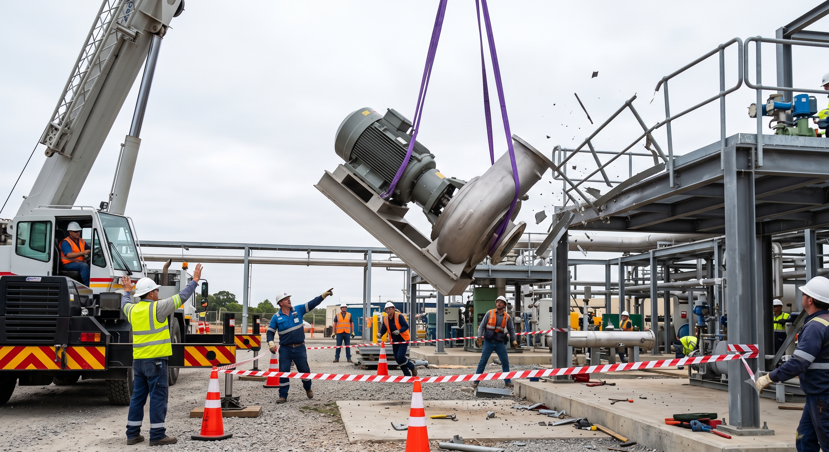
The original educational image is retained. It is not evidence of an actual incident or site suitability.
The scenario and record comparisons are fictional teaching examples, not records of real incidents, measurements, inspections, signatures or approvals.
| Item | Fictional scenario |
|---|---|
| Initial situation | A fictitious pump skid is to be moved to a prepared platform. The motor end is heavier and retained liquid has not yet been accounted for. |
| Changed condition | The crane’s nominal capacity is cited as sufficient, while slings are placed around smooth casing that was not identified as a lifting point. |
| Failure path | During a low controlled trial lift, the skid tilts and a sling begins migrating. A continued lift could drop or swing the load into the platform. |
| Possible outcome | The operator stops and returns the load to stable support while people remain clear. The team verifies mass, lifting points and a suitable rigging arrangement. |
| Prevention barrier | The revised setup is checked against the full route and landing. The scenario supplies no measured incident cost, casualty count or claim of an official investigation. |
Failure mechanisms
Capacity changes with radius and configuration. Include the load and chart-required deductions exactly once; do not compare gross suspended weight with an already deducted net capacity and then subtract the same gear again. A capacity indicator cannot compensate for a wrong setup entry or weak ground.
Outrigger reactions vary through the lift. They are not obtained safely by dividing total weight by four or by assuming the whole crane always sits on one foot. Mat area, stiffness, bearing strata, edges and buried voids need a competent support assessment.
For an ideal static, symmetric two-leg sling, leg force is W/(2 sin θ), with θ measured from horizontal. At 60° it is about 0.577W and at 30° it is W; this is not an exponential law and does not model unequal loading, four-leg sharing or hitch reductions. Use the rated assembly’s instructions.
Smooth acceleration reduces shock loading, while a trial lift exposes imbalance and slippage before travel. A design safety factor is not spare working capacity. Rotational energy is ½Iω²; no fixed stand-off or pair of taglines guarantees control of a turning load.
Decision sequence
| Decision stage | What to verify |
|---|---|
| Known facts | Verify load mass, lifting points and centre of gravity, then choose the crane configuration and route with all chart deductions. |
| Unresolved matters | Establish support reactions, bearing evidence and suitable mats; set the crane within the manufacturer levelling tolerance. |
| Reason to hold | Inspect the crane and rigging by the required method; quarantine faults rather than bypass devices or perform improvised overload tests. |
| Required evidence | Take the load gently to the low trial-lift position specified in the lift plan; stop for unstable support, tilt, slip or unexpected readings. |
| Restart decision | Travel within the accepted envelope, land on prepared support and demonstrate load stability before rigging removal and controlled stowage. |
5. Conditional decisions and common errors
| Condition | Action | Evidence | Proceed when |
|---|---|---|---|
| Setup mismatch | Resolve configuration and support | Chart, reactions and ground evidence | Setup matches plan |
| Trial-lift anomaly | Return to support and reassess | Rigging, balance and support checks | Stable rigging and load |
| Route change | Hold safely and restore controls | Clear path and agreed communication | Path and signals clear |
| Unstable landing | Complete planned support/restraint | Landing capacity and restraint checks | Self-support confirmed |
Similar situations, different decisions
The scenario and record comparisons are fictional teaching examples, not records of real incidents, measurements, inspections, signatures or approvals.
| Comparison | Situation A | Situation B |
|---|---|---|
| Capacity | A light load compared with the crane model name | The actual chart for the worst radius, sector and setup with deductions |
| Trial lift | A fixed 300 mm and five-second rule used as proof | A planned low check of balance, attachment, braking and support; stop on abnormality |
| Taglines | Two ropes assumed to make a load electrically safe | Select safe guidance after entanglement, snagging, wind and electrical exposure assessment |
6. Roles and responsibilities
| Role | Responsibility |
|---|---|
| Lift planner | Define mass, chart configuration, rigging and support requirements; obtain specialist design where needed. |
| Lift supervisor | Confirm site controls, hold points and changes; authorise continuation only after actual checks. |
| Crane operator | Inspect and set the crane, verify the applicable chart and respond to the agreed signal protocol; stop on danger or signal loss. |
| Rigger / signal person | Check attachment and safe positions; use one designated movement signal source while recognising an emergency stop from anyone. |
| Ground / receiving team | Maintain the exclusion route and prepare a stable landing; report changes and confirm the receiving condition before release. |
Supervision, records, handover
| Job stage | Technical and procedural controls | Site verification |
|---|---|---|
| Accept lift basis | 1. Confirm load proof2. Accept rigging plan3. Review route | 1. Load data2. Lift-point proof3. Path plan |
| Release setup | 1. Accept support design2. Match setup3. Close defects | 1. Ground report2. Chart issue3. Inspection record |
| Accept rigging | 1. Check configuration2. Inspect edges3. Confirm geometry | 1. Gear register2. Edge protection3. Pick layout |
| Authorise travel | 1. Observe low trial2. Stop on change3. Confirm clear lift | 1. Trial observation2. Ground condition3. Proceed person |
| Control landing | 1. Confirm receiving base2. Keep hands clear3. Control release | 1. Base proof2. Load restraint3. Release record |
| Close operation | 1. Confirm clearance2. Secure equipment3. Transfer defects | 1. Stowage check2. Travel state3. Handover person |
7. Hold points and record comparison
| Hold point | Evidence before release | Confirmation / approval |
|---|---|---|
| Start | Planned mobile-crane lifts of identified construction or plant components from a known support to a prepared landing position, with competent operation, rigging and signalling. | |
| HP-1 Set crane support | Ground evidence · Mat and reactions · Extension and level · Boundary control | |
| HP-2 Trial lift | Balance and grip · Rigging behaviour · Ground movement · Proceed decision | |
| HP-3 Land and release | Support contact · Load restraint · Rigging slack · Release authority | |
| HP-4 Stow and close | Hook clearance · People clear · Travel condition · Handover record |
Complete after actual checks. Recheck after changes, defects or shift handover.
Record comparison examples
The scenario and record comparisons are fictional teaching examples, not records of real incidents, measurements, inspections, signatures or approvals.
The boxes are static record prompts, not interactive or saved approvals. A tick does not establish suitability or permission to restart. Record the evidence, person, time and unresolved issues; retain the change history.
| Record type | Insufficient record | Record checklist |
|---|---|---|
| Lift basis | Below the crane nameplate capacity | □ Load evidence□ Centre of gravity□ Chart configuration□ Maximum radius |
| Support | Ground looks firm | □ Reaction envelope□ Ground evidence□ Mat arrangement□ Level condition |
| Trial | Lift looked fine | □ Rigging IDs□ Balance observation□ Device response□ Proceed decision |
| Landing | Load landed | □ Landing capacity□ Load restraint□ Rigging slack□ Release authority |
8. Site checklist and emergency response
| Check item | Result | Person / action |
|---|---|---|
| □ Define the lift: Mass evidence | ||
| □ Inspect and configure: Rope and hook | ||
| □ Set crane support: Ground evidence | ||
| □ Attach rigging: Rigging ID and WLL | ||
| □ Trial lift: Balance and grip | ||
| □ Slew and transfer: Service clearance | ||
| □ Land and release: Support contact | ||
| □ Stow and close: Hook clearance | ||
| □ Release / handover authority |
Stop work
Stop for unknown mass, chart mismatch, device fault, ground movement, rigging slip, snagging, unexpected tilt, lost signals, entry into the exclusion zone or conditions outside the plan. Lower to a safe support if this can be done under the planned procedure; never use the crane to pull a stuck load free.
Emergency response
Warn and isolate the area on uncontrolled movement, support failure or suspected electrical contact. Follow the site emergency procedure and utility instructions; prevent people approaching the crane, load or rigging. Do not attempt a hand rescue within an unstable load path.
9. Sources and review limits
2026-10-08
| Source | Scope and limitations |
|---|---|
| Safe Work Australia - Mobile cranes | Official guidance on configurations, load charts, support and wind; 2015 guidance, not a site approval. |
| SafeWork NSW - HRW licences | Official licence classes inspected as a NSW example; task and jurisdiction determine the required class. |
| Liebherr - Influence of wind | Manufacturer educational material on wind effects; not the operating or erection manual for the actual crane. No model-specific limit is transferred. |
This is reference content written and revised with AI. It has not been verified or approved by a professional. Review by a suitably qualified professional and site authorisation are required before use.
10. PDF guidance and FAQ
PDF A covers basic task controls; B focuses on technical failures; C covers supervision, records and handover. The article has eight stages with four items per main cell; each PDF has six key stages with three items per main cell. P/S/R/A, measurements, confirmations and signatures remain blank for actual site assessment.
Content group ID
jsa-crane-operation
Must every outrigger always be fully extended?
Use the manufacturer-permitted configuration and its matching chart. Never apply a full-extension chart to a reduced setup. If no approved reduced configuration exists, it cannot be improvised.
Is a 300 mm, five-second pause universal law?
This review does not establish that. Set a low trial-lift position and sufficient observation time in the actual lift plan and follow applicable local and manufacturer requirements.
Does a design factor permit shock or overload?
No. Use the working load limit for the hitch, angle and condition; safety factors are not extra lifting capacity.
Can synthetic taglines protect against power lines?
No. Wet or contaminated ropes can conduct; taglines do not replace isolation, utility coordination or required electrical clearances.
Has a professional verified or approved this document?
No. Public sources and editorial, layout and consistency checks were reviewed using AI. No site inspection or professional technical approval has been performed. Obtain appropriate professional review before use.
11. Revision history and authorship
This is reference content written and revised with AI. It has not been verified or approved by a professional. Review by a suitably qualified professional and site authorisation are required before use.
| Date | Version | Change | Review status |
|---|---|---|---|
| 2026-06-27 | Original version unmarked | Original preserved | No professional approval |
| 2026-10-08 | 1.1 | Decisions, records, JSA and PDFs revised | No professional approval |
Retained chart verification, outrigger support, pre-use inspection, centre-of-gravity checks, edge protection, trial lifting, one signalling protocol and stable landing. Removed unverified universal 100/105% cutout, 0.6 m A2B clearance, 3-times-foot mat area, 300 mm/five-second stop, two 12 mm ropes/3 m distance, fixed design factors and prohibition of every single-choker hitch. Corrected sling-angle assumptions, unequal reactions, energy formula and safety-factor misuse. Replaced the unsourced accident costs and professional-review claims with fictional training content and explicit AI disclosure. Verify actual crane-operation, dogging and rigging licence classes and the relevant SWMS triggers with the state or territory regulator. The Safe Work Australia mobile-crane guide supports chart/configuration and wind assessment. AS 2550.5, AS 4497, AS 1353 and AS 2741 full texts were not reviewed; the original 105% trip setting and mandatory 300 mm rule are not certified.