A crane release is a transfer of support. Before it happens, identify the temporary load path from the member through its connections, bracing and base to the ground. A visible bolt, an upright column or a completed lifting checklist does not demonstrate that the whole erection stage is stable.
Erection sequence → ground and access → column support → beam connection → final joints → decking → change review → handover
This is reference content written and revised with AI. It has not been verified or approved by a professional. Review by a suitably qualified professional and site authorisation are required before use.
Stop work
Stop for missing bracing, unapproved anchor or hole changes, an unexplained movement, lost communications, unsuitable access ground, wind outside the assessed limit or unsecured decking. Keep personnel out of the affected bay. Do not test stability by walking on it or shock-loading it with the crane.
1. Legal and technical scope
| Basis | Application limits |
|---|---|
| Safe Work Australia - Steel erection | Official guidance overview; national guidance rather than state enforcement. |
| Steel erection information sheet | Design/erection responsibilities, high-risk triggers, SWMS and skills. Older guidance; verify current jurisdictional thresholds. |
| HSE - Steel erection | Foreign technical comparison only; not Australian law. |
Australia: the state or territory regulator determines applicable WHS/OHS law and licensing. Safe Work Australia publishes national policy and guidance; it is not the site regulator. Model requirements must not be treated as identical enacted law everywhere.
Assess the actual high-risk construction work triggers and prepare the required SWMS before starting that work. Relevant triggers may include falls, temporary structural support, services and moving powered plant. Confirm dogging, rigging, crane and platform licence requirements for assigned tasks. AS 3828 and product-specific Bondek/Condeck manuals were named in the original but their full current texts were not reviewed; neither a universal four-anchor rule nor a 50 mm bearing or 35 km/h wind limit is verified here.
2. Scope and required inputs
Included scope
Delivery and lifting of identified steel columns and beams, temporary bracing, final bolting and field welding, metal decking and controlled shift handover. The eight stages separate temporary stability from final connection acceptance.
Separate review
Open-web joists, proprietary building systems, demolition, tandem lifts and modifications to anchors or connection holes need their own engineered procedure. This article does not design a lift, temporary works, lifeline or structural connection.
| Required input | What to verify |
|---|---|
| Sequence and support | Identify the current erection drawing, member marks, temporary bracing layout, connection release criteria and the point at which permanent stability replaces temporary support. |
| Crane and access | Obtain load and rigging data, ground bearing assessment, underground/overhead service controls, crane setup, platform access, communications and rescue method. |
| Connections and deck | Identify anchor condition, base support, specified bolt assemblies and tightening method, welding procedure, inspection plan, deck span/bearing/fasteners and permitted landing loads. |
| Change and handover | Record wind and visibility criteria, incomplete bays, fire-watch arrangements, hold points, responsible persons and restrictions to pass to the next crew. |
Member mass, centre of gravity, rigging angle, crane configuration, foundation strength, temporary bolt arrangement, deck bearing and fastening, bundle loading and wind limits must come from the actual design and equipment instructions. Paid CSA/AS/ANSI standards and project records were not supplied or reviewed in full. No universal wind speed, bearing length or tagline count is prescribed here.
3. Eight-stage JSA
| Job stage | Hazards and effects | Failure factors | Technical and procedural controls | Site verification | P | S | R | A |
|---|---|---|---|---|---|---|---|---|
| 1. Plan erection | 1. Frame collapse2. Unsafe access3. Service contact4. Wrong member | 1. Old drawings2. Missing load path3. Unknown ground4. Unplanned changes | 1. Confirm erection sequence2. Design temporary bracing3. Plan protected access4. Resolve deviations first | 1. Drawing revision2. Stability stages3. Access and rescue4. Change authority | ||||
| 2. Deliver and rig | 1. Dropped steel2. Crushing3. Cuts4. Crane overturn | 1. Wrong sling angle2. Unstable stack3. Weak outrigger ground4. Poor communications | 1. Use rated rigging2. Secure stored steel3. Verify crane support4. Agree lift signals | 1. Mass and lift points2. Rigging condition3. Ground capacity4. Lift route | ||||
| 3. Erect column | 1. Column overturn2. Base crushing3. Anchor failure4. Frame movement | 1. Unsupported base2. Damaged rods3. Missing braces4. Early crane release | 1. Check base and anchors2. Install specified braces3. Exclude pinch points4. Release after stability check | 1. Base support2. Anchor disposition3. Brace connections4. Release criteria | ||||
| 4. Connect beam | 1. Worker fall2. Beam rotation3. Hand trapping4. Dropped hardware | 1. Unsafe access2. Incomplete far joint3. Forced alignment4. Shared bolt removed | 1. Use planned platform2. Secure both connections3. Keep hands clear4. Control shared connections | 1. Safe access2. Bolt arrangement3. Temporary load path4. Release decision | ||||
| 5. Complete joints | 1. Joint failure2. Falling tools3. Fire4. Welding fume | 1. Wrong tightening2. Loose equipment3. Exposed combustibles4. Poor fume control | 1. Follow joint procedure2. Secure tools and area3. Apply hot-work controls4. Control fume exposure | 1. Bolt inspection2. Weld inspection3. Fire-watch plan4. Ventilation and PPE | ||||
| 6. Install decking | 1. Fall through2. Bundle overload3. Windblown sheet4. Falling scraps | 1. Insufficient bearing2. Unverified landing bay3. Delayed fastening4. Unprotected opening | 1. Verify supports and load2. Use specified fasteners3. Secure sheets promptly4. Protect every opening | 1. Bearing and span2. Bundle landing load3. Fixings and edges4. Opening protection | ||||
| 7. Review changes | 1. Progressive collapse2. Fall during rescue3. Hidden defect4. Uncontrolled restart | 1. Brace removed early2. Wind/access change3. Damage not reported4. No rescue arrangement | 1. Hold affected bay2. Reassess changed loads3. Inspect after incident4. Confirm rescue readiness | 1. Brace status2. Weather and access3. Defect disposition4. Restart authority | ||||
| 8. Close and hand over | 1. Falling remnants2. Unsafe next shift3. Plant collision4. Premature loading | 1. Loose items aloft2. Restrictions lost3. Unplanned crane exit4. Incomplete joints | 1. Lower loose materials2. Record bay limitations3. Control demobilisation4. Authorise loading stage | 1. Cleared work area2. Remaining braces3. Joint records4. Receiving crew |
PDF A covers basic task controls; B focuses on technical failures; C covers supervision, records and handover. The article has eight stages with four items per main cell; each PDF has six key stages with three items per main cell. P/S/R/A, measurements, confirmations and signatures remain blank for actual site assessment.
4. Fictional scenario and failure mechanisms
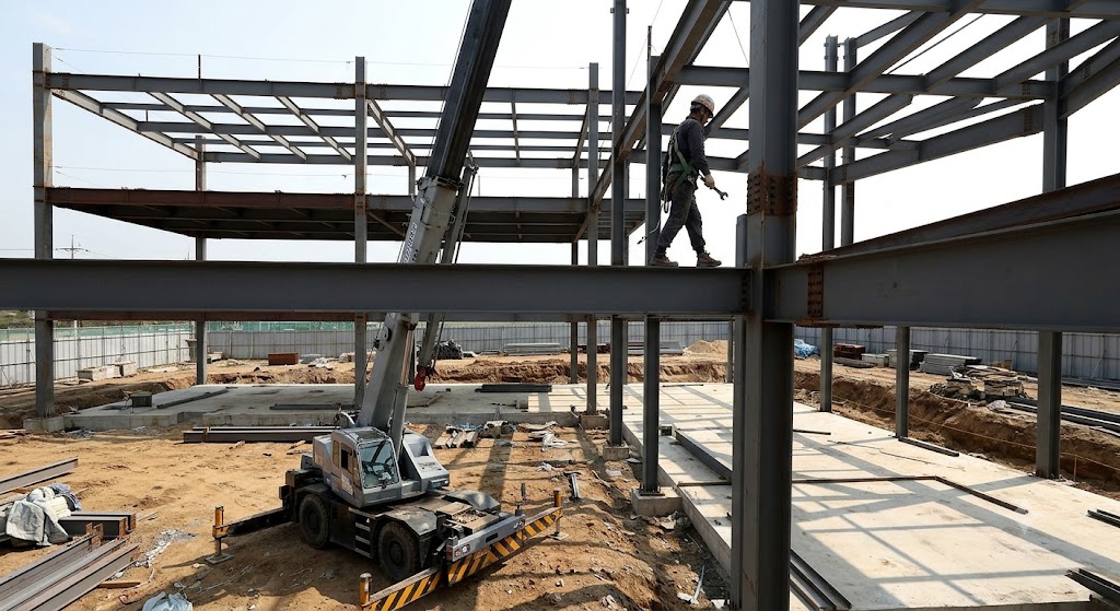
The original educational image is retained. It is not evidence of an actual incident or site suitability.
The scenario and record comparisons are fictional teaching examples, not records of real incidents, measurements, inspections, signatures or approvals.
| Item | Fictional scenario |
|---|---|
| Initial situation | Fictional example: a beam is in position and the crane still supports it. |
| Changed condition | The planned access platform cannot reach the joint because its ground route has deteriorated. |
| Failure path | The crew proposes walking the beam and releasing the crane after seeing bolts at one end, without checking the opposite connection and braced bay. |
| Possible outcome | Fit-up force or wind may move the incompletely restrained member and expose a worker to a fall. |
| Prevention barrier | Hold the lift stage; restore suitable access and verify both connections and the temporary stability system before release. |
Failure mechanisms
Stability depends on a complete load path at every erection stage. Final design strength is not automatically available before bracing, connections and base support are complete. An upright column can still lack restraint in one direction. Bolt quantity alone cannot establish base capacity or authorise an anchor repair.
A partly connected beam can rotate or move under fit-up forces. This motion is not, by itself, proof of lateral-torsional buckling. Keep hands out of pinch points and use the planned access and alignment method. A crane must not be used to force an unapproved alteration into fit.
Temporary connection acceptance and final bolt pretension or weld acceptance are separate decisions. Wrench-tight, snug-tight and specified pretension are not interchangeable instructions. Identify the joint category, fastener assembly, installation method and required inspection before recording completion.
Deck sheets and bundles introduce different loads. Landing a bundle on an unverified bay can overload the frame even if individual sheets fit. Loose sheets can slip, lift in wind or conceal openings; bearing, support, fastening sequence and hole protection must be checked before access. Debris netting is not automatically a personnel fall-arrest system.
Decision sequence
| Decision stage | What to verify |
|---|---|
| Known facts | The beam is positioned; platform access has changed and crane support remains. |
| Unresolved matters | Ground suitability, both end connections and bracing release criteria remain unverified. |
| Reason to hold | The approved access and support-transfer sequence cannot currently be followed. |
| Required evidence | Obtain access-ground reassessment, the current erection drawing, connection checks and braced-bay inspection. |
| Restart decision | Resume only when safe access and the specified support path are demonstrated and the designated release authority agrees. |
5. Conditional decisions and common errors
| Condition | Action | Evidence | Proceed when |
|---|---|---|---|
| Access ground changed | Hold connection work | Ground and platform reassessment | Safe access ready |
| Anchor differs | Hold column release | Designer disposition and repair record | Base accepted |
| Connection incomplete | Retain planned support | Both ends and bracing checked | Stable stage confirmed |
| Loose deck or wind | Stop spreading; secure safely | Deck fixing and weather review | Deck stage controlled |
Similar situations, different decisions
The scenario and record comparisons are fictional teaching examples, not records of real incidents, measurements, inspections, signatures or approvals.
| Comparison | Situation A | Situation B |
|---|---|---|
| Visible state | Bolts fitted at a beam end | Bolts fitted at a beam end |
| Evidence | Count alone; opposite end and bracing unknown | Specified temporary connections and full bracing path checked |
| Decision | Keep the hold point; final torque alone cannot close it | Release only this erection stage; final joint inspection still follows |
6. Roles and responsibilities
| Role | Responsibility |
|---|---|
| Erection designer / engineer | Defines the erection sequence, temporary stability, connection criteria and disposition of deviations within the assigned responsibility. |
| Lift supervisor and operator | Coordinate the planned lifting stage, rigging, communications, exclusion and controlled support transfer. |
| Erection crew | Use the planned access, install identified parts and report mismatches before modifying anchors, holes or supports. |
| Connection inspector | Records the actual tightening and welding inspection scope; a check mark is not a structural design approval. |
| Handover authority | Confirms stage limits, remaining braces, deck loading restrictions, rescue arrangements and acceptance by the receiving crew. |
Supervision, records, handover
| Job stage | Technical and procedural controls | Site verification |
|---|---|---|
| Define sequence | 1. Approve stage sequence2. Assign stability duties3. Plan access and rescue | 1. Drawing issue2. Brace design3. Rescue method |
| Release lift setup | 1. Confirm support ground2. Accept rigging plan3. Brief one signal system | 1. Ground evidence2. Gear record3. Lift briefing |
| Release support | 1. Check base and braces2. Verify both connections3. Control release signal | 1. Member IDs2. Connection evidence3. Release authority |
| Accept joints | 1. Define inspection scope2. Close nonconformities3. Control hot work | 1. Bolt record2. Weld record3. Fire-watch record |
| Control deck | 1. Approve bundle position2. Inspect sheet fixing3. Protect openings | 1. Load restriction2. Fastening record3. Opening register |
| Hand over bay | 1. Confirm brace status2. Clear elevated work3. Transfer restrictions | 1. Stability evidence2. Cleanup check3. Receiving authority |
7. Hold points and record comparison
| Hold point | Evidence before release | Confirmation / approval |
|---|---|---|
| Start | Delivery and lifting of identified steel columns and beams, temporary bracing, final bolting and field welding, metal decking and controlled shift handover. The eight stages separate temporary stability from final connection acceptance. | |
| HP-1 Erect column | Base support · Anchor disposition · Brace connections · Release criteria | |
| HP-2 Connect beam | Safe access · Bolt arrangement · Temporary load path · Release decision | |
| HP-3 Install decking | Bearing and span · Bundle landing load · Fixings and edges · Opening protection | |
| HP-4 Close and hand over | Cleared work area · Remaining braces · Joint records · Receiving crew |
Complete after actual checks. Recheck after changes, defects or shift handover.
Record comparison examples
The scenario and record comparisons are fictional teaching examples, not records of real incidents, measurements, inspections, signatures or approvals.
The boxes are static record prompts, not interactive or saved approvals. A tick does not establish suitability or permission to restart. Record the evidence, person, time and unresolved issues; retain the change history.
| Record type | Insufficient record | Record checklist |
|---|---|---|
| Column | Four anchors seen | □ Member and base ID□ Anchor condition/deviations□ Base support evidence□ Temporary bracing release |
| Connection | Bolts tight | □ Both connection IDs□ Bolt grade and arrangement□ Specified tightening stage□ Inspector and unresolved items |
| Deck | Sheets laid | □ Approved bearing and span□ Fasteners and openings□ Bundle load location□ Wind and access restrictions |
| Handover | Bay complete | □ Permanent stability evidence□ Remaining temporary supports□ Weld/bolt inspection status□ Next crew and release limits |
8. Site checklist and emergency response
| Check item | Result | Person / action |
|---|---|---|
| □ Plan erection: Drawing revision | ||
| □ Deliver and rig: Mass and lift points | ||
| □ Erect column: Base support | ||
| □ Connect beam: Safe access | ||
| □ Complete joints: Bolt inspection | ||
| □ Install decking: Bearing and span | ||
| □ Review changes: Brace status | ||
| □ Close and hand over: Cleared work area | ||
| □ Release / handover authority |
Stop work
Stop for missing bracing, unapproved anchor or hole changes, an unexplained movement, lost communications, unsuitable access ground, wind outside the assessed limit or unsecured decking. Keep personnel out of the affected bay. Do not test stability by walking on it or shock-loading it with the crane.
Emergency response
Warn the lift supervisor, isolate the collapse and falling-object zone and use the planned safe withdrawal route. For a suspended worker, activate the prepared rescue arrangement with trained personnel and suitable equipment. Do not enter an unstable frame or improvise a crane rescue. Manage fire and electrical hazards before access; preserve the configuration and report the event.
9. Sources and review limits
2026-10-08
| Source | Scope and limitations |
|---|---|
| Safe Work Australia - Steel erection | Official guidance overview; national guidance rather than state enforcement. |
| Steel erection information sheet | Design/erection responsibilities, high-risk triggers, SWMS and skills. Older guidance; verify current jurisdictional thresholds. |
| HSE - Steel erection | Foreign technical comparison only; not Australian law. |
This is reference content written and revised with AI. It has not been verified or approved by a professional. Review by a suitably qualified professional and site authorisation are required before use.
10. PDF guidance and FAQ
PDF A covers basic task controls; B focuses on technical failures; C covers supervision, records and handover. The article has eight stages with four items per main cell; each PDF has six key stages with three items per main cell. P/S/R/A, measurements, confirmations and signatures remain blank for actual site assessment.
Content group ID
jsa-beam-work
Do two bolts prove a beam can be released?
Not by themselves. Check the jurisdiction-specific rule, the erection design, both connections and the temporary load path. Cantilevers, bracing and shared connections can need different or additional controls.
Can a worker walk the beam if the platform cannot reach?
A failed access arrangement is a hold point. Re-plan safe access and suitable fall protection, including anchorage, clearance and rescue. A harness alone does not make an unstable member a safe walkway.
Does final tightening permit brace removal?
No. The responsible designer’s stability sequence, completed load path and specified inspections must support removal. Record who authorises it and which stage is released.
Are debris nets and fall-arrest nets equivalent?
No. Their intended use, design, installation, clearances and inspection differ. Use a system suitable for its stated purpose; do not count debris containment as personnel protection.
Has a professional verified or approved this document?
No. Public sources and editorial, layout and consistency checks were reviewed using AI. No site inspection or professional technical approval has been performed. Obtain appropriate professional review before use.
11. Revision history and authorship
This is reference content written and revised with AI. It has not been verified or approved by a professional. Review by a suitably qualified professional and site authorisation are required before use.
| Date | Version | Change | Review status |
|---|---|---|---|
| 2026-08-30 | Original version unmarked | Original preserved | No professional approval |
| 2026-10-08 | 1.1 | Decisions, records, JSA and PDFs revised | No professional approval |
Preserved lifting checks, exclusion, column stability, elevated access, connection restraint, falling-object control, hot-work precautions, immediate deck securing and supervised demobilisation. Corrected unqualified four-anchor/two-bolt rules outside their jurisdiction, fixed wind/bearing values, automatic two-tagline instructions, debris/fall-net equivalence, and the claim that a complete frame must be statically determinate. Replaced regulator investigation narratives with a clearly fictional decision exercise and removed claims of verified automated compliance. Assess the actual high-risk construction work triggers and prepare the required SWMS before starting that work. Relevant triggers may include falls, temporary structural support, services and moving powered plant. Confirm dogging, rigging, crane and platform licence requirements for assigned tasks. AS 3828 and product-specific Bondek/Condeck manuals were named in the original but their full current texts were not reviewed; neither a universal four-anchor rule nor a 50 mm bearing or 35 km/h wind limit is verified here.