An anchor frame needs a verified temporary load path before lifting gear is released. The completed foundation needs separate acceptance before crane erection. A correct survey position alone proves neither condition.
Design → access → lifting → temporary support → survey → pre-pour inspection → pour monitoring → foundation handover
This is reference content written and revised with AI. It has not been verified or approved by a professional. Review by a suitably qualified professional and site authorisation are required before use.
Stop work
Hold the affected stage for an unverified support, unauthorised welding or anchor adjustment, loss of alignment, support movement or missing strength evidence. Do not free the crane merely because another delivery is waiting.
1. Legal and technical scope
| Basis | Application limits |
|---|---|
| Safe Work Australia - tower crane model code | Pages 36-37: foundation design factors, site-specific geotechnical input and competent verification; check local adoption. |
| Safe Work Australia - adoption and scope | Model status and regulator responsibility. |
| HSE - temporary works | Foreign technical reference on support design and installation; not Australian law. |
Australia: identify the state or territory and the adopted WHS requirements. Safe Work Australia publishes model guidance and does not regulate each site. Determine the applicable high risk construction work, SWMS and dogging/rigging licence requirements for the actual activity.
The June 2023 tower-crane model code addresses site-specific foundations, ground conditions and competent engineering verification. It is not evidence that this foundation has been certified. AS 2550.4 was not reviewed in full; no universal tolerance or full-standard compliance is asserted.
2. Scope and required inputs
Included scope
Delivery and installation of the identified embedded anchor assembly, temporary restraint, reinforcement interfaces, concrete placement monitoring and foundation handover before tower erection.
Separate review
Geotechnical and foundation design, tower erection or climbing, changes of crane configuration and acceptance of reused anchors require separate specialist assessment.
| Required input | What to verify |
|---|---|
| Design and product | Match crane configuration and reactions, ground investigation, foundation design, anchor identity, material and drawing revision. |
| Lifting and support | Confirm assembly mass, centre of gravity, lifting points, crane setup, temporary supports and their actual attachment substrates. |
| Survey and pour | Define stable benchmarks, coordinates, level, plumb, tolerances, reinforcement clearances and monitoring/stop criteria during placement. |
| Handover | Link curing and strength evidence, final survey, thread protection, defect disposition and the authorised release for crane erection. |
Obtain the actual manufacturer instructions and approved design for lifting points, support layout, fixings, permitted welding, geometric tolerances, pour sequence and required concrete strength. Four directions, 1/1000, 300-mm layers, 45-60-degree braces and two-person handling are not universal acceptance criteria. A hot-work permit does not authorise welding a prohibited component.
3. Eight-stage JSA
| Job stage | Hazards and effects | Failure factors | Technical and procedural controls | Site verification | P | S | R | A |
|---|---|---|---|---|---|---|---|---|
| 1. Confirm design and anchor | 1. Foundation failure2. Wrong interface3. Settlement4. Overturning | 1. Wrong crane model2. Wrong anchor grade3. Unknown soil4. Old drawing | 1. Match crane reactions2. Identify anchor assembly3. Check ground evidence4. Use approved revision | 1. Crane configuration2. Anchor identity3. Foundation design4. Ground report | ||||
| 2. Prepare pit and access | 1. Edge fall2. Plant collision3. Wall collapse4. Impalement | 1. Open edge2. Shared route3. Unstable excavation4. Exposed rebar | 1. Protect excavation edges2. Separate survey access3. Verify excavation support4. Guard fall-onto hazards | 1. Edge protection2. Access route3. Excavation condition4. Rebar protection | ||||
| 3. Lift and position frame | 1. Dropped frame2. Swing impact3. Pinched hands4. Crane instability | 1. Damaged sling2. Poor load control3. Hands below base4. Weak crane support | 1. Check rated lifting gear2. Use agreed signals3. Keep out of pinch zone4. Verify crane setup | 1. Mass and lift points2. Gear inspection3. Exclusion and signals4. Crane support | ||||
| 4. Secure temporary support | 1. Frame overturn2. Brace pullout3. Crushing4. Sudden load transfer | 1. Early unhooking2. Weak attachment3. Improvised tack weld4. Missing load path | 1. Fit designed supports2. Check attachment substrate3. Permit only specified joints4. Control load transfer | 1. Support detail2. Installed connections3. Competent stability check4. Release decision | ||||
| 5. Survey and inspect joints | 1. Misalignment2. Material damage3. Fire4. Fume exposure | 1. Wrong benchmark2. Unapproved heating3. Combustibles nearby4. Poor ventilation | 1. Check survey references2. No unauthorised repair3. Control permitted hot work4. Assess fume controls | 1. Position and level2. Product tolerances3. Joint permission4. Inspection disposition | ||||
| 6. Inspect before concrete | 1. Hidden defect2. Cage collapse3. Anchor shift4. Impalement | 1. Rebar interference2. Weak mat support3. Brace disturbed4. Unsafe bar ends | 1. Check embedment space2. Support reinforcement3. Recheck frame restraint4. Protect exposed bars | 1. Embedment and cover2. Rebar support3. Pre-pour survey4. Pour hold release | ||||
| 7. Place and monitor concrete | 1. Frame displacement2. Hose strike3. Concrete burns4. Loss of escape | 1. Unbalanced placement2. Hose whipping3. Skin contact4. Blocked access | 1. Follow approved sequence2. Control pump zone3. Use concrete protection4. Monitor and stop on change | 1. Placement sequence2. Pump communication3. Displacement readings4. Support condition | ||||
| 8. Cure and hand over | 1. Premature loading2. Mast misfit3. Connection failure4. Hidden defect | 1. Strength unverified2. Final survey missing3. Damaged threads4. Open deviation | 1. Protect curing concrete2. Complete final survey3. Protect and inspect anchors4. Release erection separately | 1. Strength evidence2. As-built geometry3. Anchor condition4. Accepted handover |
PDF A covers basic task controls; B focuses on technical failures; C covers supervision, records and handover. The article has eight stages with four items per main cell; each PDF has six key stages with three items per main cell. P/S/R/A, measurements, confirmations and signatures remain blank for actual site assessment.
4. Fictional scenario and failure mechanisms
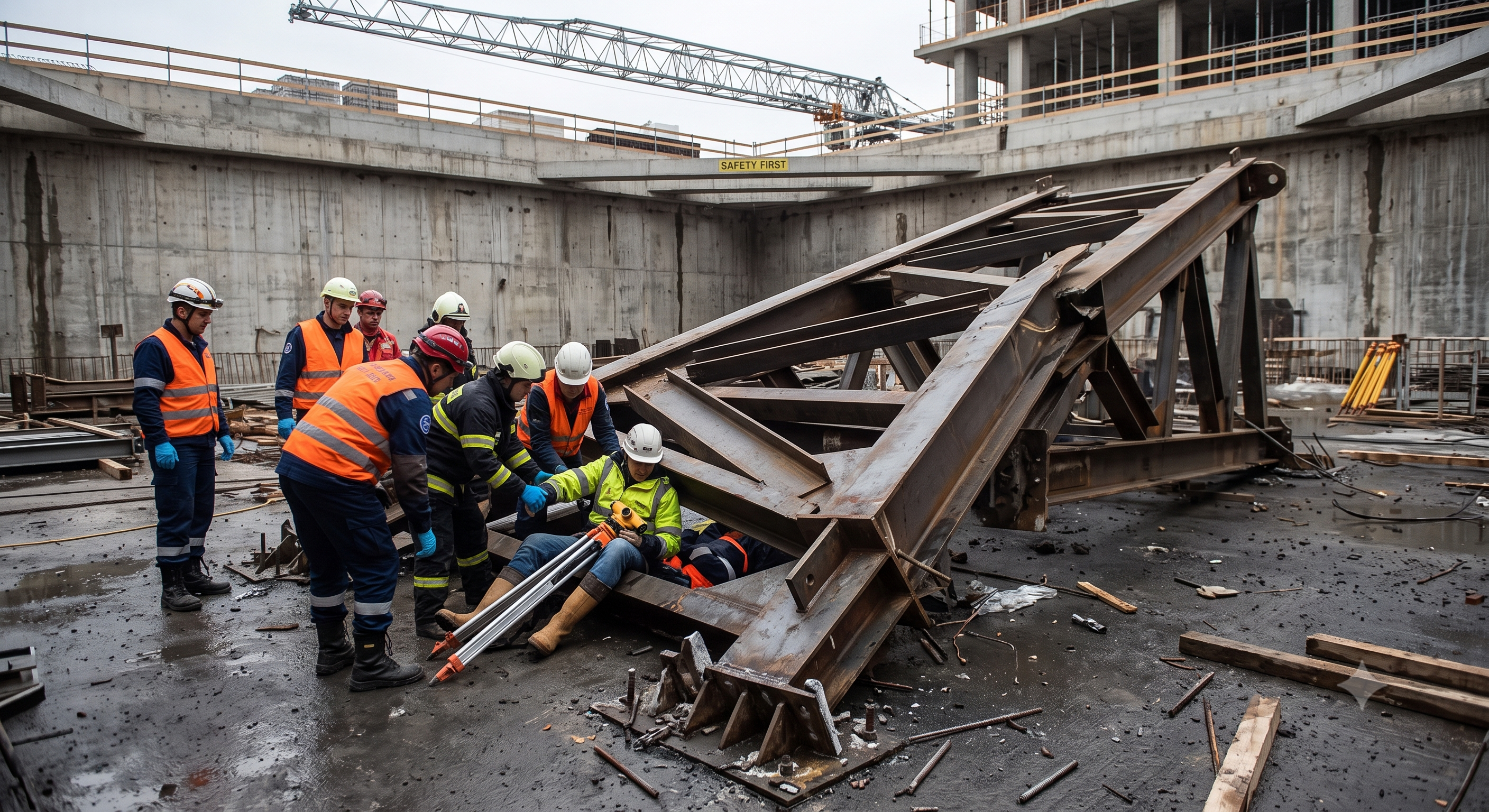
The original educational image is retained. It is not evidence of an actual incident or site suitability.
The scenario and record comparisons are fictional teaching examples, not records of real incidents, measurements, inspections, signatures or approvals.
| Item | Fictional scenario |
|---|---|
| Initial situation | Fictional example: the frame is positioned and the survey is within the specified tolerance. |
| Changed condition | The lifting crane is requested for another delivery before the temporary fixing has been checked. |
| Failure path | Releasing the sling transfers load to an unverified support and attachment. |
| Possible outcome | The frame may overturn and trap a surveyor beside the base. |
| Prevention barrier | Maintain the planned lifting support and exclusion until the temporary load path is confirmed. |
Failure mechanisms
Before embedment, the frame, braces, connections and bearing surface form a temporary load path. Tie wire and improvised tack welds are not substitutes for designed restraint. Guy wires resist tension; their presence does not prove compression restraint or attachment capacity.
Survey accuracy describes geometry, not support strength. An upright frame can still be unstable. Heating, cutting, bending or welding an anchor without the designer/manufacturer process can change material properties and invalidate its intended load path.
Concrete placement and vibration can displace or twist the assembly. Compare readings against a stable benchmark before, during and after the pour. Agree a controlled pour-stop method; do not correct a displaced anchor by force while concrete is moving.
Curing time alone is not foundation acceptance. Verify the design strength condition and its evidence, final geometry and unresolved defects before erection loads are applied. Small cap-type rebar covers may limit cuts without providing protection against a person falling onto the bar; select suitable protection for the actual fall exposure.
Decision sequence
| Decision stage | What to verify |
|---|---|
| Known facts | Record the survey result and how the crane currently supports the frame. |
| Unresolved matters | The temporary attachment substrate and connection inspection are unresolved. |
| Reason to hold | Do not unhook: the next load path has not been demonstrated. |
| Required evidence | Obtain the support detail, installation check and planned load-transfer sequence. |
| Restart decision | Release only after the designated competent person confirms stability; retain the separate pre-pour hold point. |
5. Conditional decisions and common errors
| Condition | Action | Evidence | Proceed when |
|---|---|---|---|
| Support unverified | Keep planned lifting support | Brace detail and attachment checks | Support confirmed |
| Anchor out of tolerance | Stop; prohibit improvised adjustment | Survey and designer disposition | Repair approved |
| Movement during pour | Stop placement; clear the danger zone | Movement and support reassessment | Stability restored |
| Strength not demonstrated | Hold tower erection | Strength evidence and handover | Foundation accepted |
Similar situations, different decisions
The scenario and record comparisons are fictional teaching examples, not records of real incidents, measurements, inspections, signatures or approvals.
| Comparison | Situation A | Situation B |
|---|---|---|
| Survey | Position within tolerance | Position within tolerance |
| Support | Checked detail and attachments | Only improvised tack welds |
| Decision | Assess controlled unhooking | Hold lifting-gear release |
6. Roles and responsibilities
| Role | Responsibility |
|---|---|
| Foundation designer | Defines loads, foundation and acceptance conditions; resolves deviations. |
| Lifting supervisor | Coordinates the lift, exclusion, signals and controlled release. |
| Temporary works lead | Checks the support design, actual attachments and installation before transfer. |
| Survey / concrete team | Records geometry and controls placement against agreed limits. |
| Erection release authority | Accepts the foundation evidence and outstanding-item disposition before mast assembly. |
Supervision, records, handover
| Job stage | Technical and procedural controls | Site verification |
|---|---|---|
| Agree design basis | 1. Obtain design inputs2. Check product traceability3. Assign design authority | 1. Current drawings2. Product identity3. Ground evidence |
| Coordinate lifting | 1. Assign lift supervision2. Separate work zones3. Confirm access plan | 1. Lift plan2. Signals and exclusion3. Access condition |
| Release lifting gear | 1. Review installed restraint2. Check load path3. Record release decision | 1. Support inspection2. Attachment evidence3. Release authority |
| Release concrete pour | 1. Close pre-pour checks2. Agree monitoring limits3. Confirm reinforcement support | 1. Survey record2. Inspection release3. Monitoring plan |
| Manage deviation | 1. Stop affected work2. Request specialist disposition3. Reinspect correction | 1. Deviation record2. Approved method3. Reinspection evidence |
| Accept foundation | 1. Review strength evidence2. Check final geometry3. Close erection handover | 1. Strength record2. As-built survey3. Erection release |
7. Hold points and record comparison
| Hold point | Evidence before release | Confirmation / approval |
|---|---|---|
| Start | Delivery and installation of the identified embedded anchor assembly, temporary restraint, reinforcement interfaces, concrete placement monitoring and foundation handover before tower erection. | |
| HP-1 Secure temporary support | Support detail · Installed connections · Competent stability check · Release decision | |
| HP-2 Inspect before concrete | Embedment and cover · Rebar support · Pre-pour survey · Pour hold release | |
| HP-3 Place and monitor concrete | Placement sequence · Pump communication · Displacement readings · Support condition | |
| HP-4 Cure and hand over | Strength evidence · As-built geometry · Anchor condition · Accepted handover |
Complete after actual checks. Recheck after changes, defects or shift handover.
Record comparison examples
The scenario and record comparisons are fictional teaching examples, not records of real incidents, measurements, inspections, signatures or approvals.
The boxes are static record prompts, not interactive or saved approvals. A tick does not establish suitability or permission to restart. Record the evidence, person, time and unresolved issues; retain the change history.
| Record type | Insufficient record | Record checklist |
|---|---|---|
| Design | Drawing checked | □ Crane and anchor ID□ Design reactions□ Foundation revision□ Ground conditions |
| Support | Four braces fitted | □ Support layout□ Attachment substrate□ Permitted connections□ Load-transfer sequence |
| Survey | Plumb satisfactory | □ Stable benchmark□ Coordinates and level□ Specified tolerances□ Before/during/after changes |
| Handover | Curing complete | □ Strength evidence□ Anchor and thread condition□ Closed defects□ Erection release |
8. Site checklist and emergency response
| Check item | Result | Person / action |
|---|---|---|
| □ Confirm design and anchor: Crane configuration | ||
| □ Prepare pit and access: Edge protection | ||
| □ Lift and position frame: Mass and lift points | ||
| □ Secure temporary support: Support detail | ||
| □ Survey and inspect joints: Position and level | ||
| □ Inspect before concrete: Embedment and cover | ||
| □ Place and monitor concrete: Placement sequence | ||
| □ Cure and hand over: Strength evidence | ||
| □ Release / handover authority |
Stop work
Hold the affected stage for an unverified support, unauthorised welding or anchor adjustment, loss of alignment, support movement or missing strength evidence. Do not free the crane merely because another delivery is waiting.
Emergency response
Stop lifting or pumping and clear the potential collapse zone. Keep people away from an unstable frame, including rescuers until a safe access method is established. Obtain specialist stabilisation and emergency assistance as required; do not attempt to catch the frame or tighten supports beneath it.
9. Sources and review limits
2026-10-08
| Source | Scope and limitations |
|---|---|
| Safe Work Australia - tower crane model code | Pages 36-37: foundation design factors, site-specific geotechnical input and competent verification; check local adoption. |
| Safe Work Australia - adoption and scope | Model status and regulator responsibility. |
| HSE - temporary works | Foreign technical reference on support design and installation; not Australian law. |
This is reference content written and revised with AI. It has not been verified or approved by a professional. Review by a suitably qualified professional and site authorisation are required before use.
10. PDF guidance and FAQ
PDF A covers basic task controls; B focuses on technical failures; C covers supervision, records and handover. The article has eight stages with four items per main cell; each PDF has six key stages with three items per main cell. P/S/R/A, measurements, confirmations and signatures remain blank for actual site assessment.
Content group ID
jsa-anchor-installation
Are four braces always sufficient?
No. Check directions, capacities, connections and substrates against the approved arrangement. Counting braces alone does not establish stability.
Can an anchor be welded after a hot-work permit is issued?
Only if the component and connection are permitted by the designer/manufacturer procedure. Fire and fume controls are additional requirements, not material approval.
Can a bent anchor be heated back into position?
Do not make an improvised repair. Obtain a documented designer/manufacturer disposition and the required reinspection.
Can erection start after a fixed curing period?
Use the specified strength, curing and handover conditions with actual evidence. Elapsed days or a good-looking surface alone are insufficient.
Has a professional verified or approved this document?
No. Public sources and editorial, layout and consistency checks were reviewed using AI. No site inspection or professional technical approval has been performed. Obtain appropriate professional review before use.
11. Revision history and authorship
This is reference content written and revised with AI. It has not been verified or approved by a professional. Review by a suitably qualified professional and site authorisation are required before use.
| Date | Version | Change | Review status |
|---|---|---|---|
| 2026-07-30 | Original version unmarked | Original preserved | No professional approval |
| 2026-10-08 | 1.1 | Decisions, records, JSA and PDFs revised | No professional approval |
Preserved lifting-gear inspection, exclusion, pit-edge protection, survey segregation, support before unhooking, permitted hot-work controls, reinforcement stability and pour monitoring. Removed unsupported universal tolerances, brace counts/angles, layer depths and guaranteed legal-compliance claims. Replaced unverified incidents and investigation outcomes with an explicit fictional scenario. Actual risk ratings, measurements and approvals remain blank.