Horizontal wet core drilling at an accepted concrete wall location using an electrically powered, mechanically anchored drill stand, planned slurry collection and supported core recovery.
Do not drill without accepted structural and embedded-service review, access control on both wall faces and a supported stand. Stop for base movement, loss of water or electrical protection, unexpected metal contact or vibration, or failed core containment.
Reference content written and revised with AI. It has not been verified or approved by a professional. Review by a suitably qualified professional and site approval are required before use.
1. Legal and technical scope
For construction silica exposure, OSHA 1926.1153 Table 1 item (vi) addresses rig-mounted core saws or drills with integrated water delivery to the cutting surface and manufacturer-compliant operation and maintenance. Its listed respiratory protection is none for both duration columns when fully and properly implemented; otherwise apply the applicable alternative exposure-control route. Use the applicable electrical provisions, including 1926.404. This wet-work method includes GFCI protection and protected connections; do not infer that a generic JSA establishes all electrical compliance.
Determine Federal OSHA or the applicable OSHA-approved State Plan, including public/private employer coverage. State Plans must be at least as effective and can impose different or additional requirements. The actual activity determines construction versus general-industry scope. Manufacturer instructions, consensus standards, project design and site approvals have distinct roles; this page is not a finding of nationwide compliance.
| Basis | Application and limits |
|---|---|
| OSHA 1926.1153 | Table 1 item (vi), full implementation requirement and alternative exposure-control framework. |
| OSHA 3929: Rig-Mounted Core Saws or Drills | December 2017 fact sheet: water at the cutting surface, slurry management, enclosed-area ventilation and electrical precautions. |
| OSHA 1926.404 | Applicable construction wiring and ground-fault protection provisions; actual supply and site program determine scope. |
| Hilti DD 150-U (03) instructions: indexed safety excerpt | Official indexed excerpt reviewed for anchor/substrate suitability and opposite-side protection. Full PDF retrieval was unavailable; obtain the current manual for the actual machine before work. |
2. Scope and required inputs
Included: Horizontal wet core drilling at an accepted concrete wall location using an electrically powered, mechanically anchored drill stand, planned slurry collection and supported core recovery.
Separate review: Overhead or downward coring, vacuum-only mounting, handheld coring, elevated access, suspected asbestos materials and decisions to cut reinforcement or post-tensioning require separate review.
| Input | Required evidence |
|---|---|
| Approve drilling location | Coordinates diameter and depth; Wall thickness and scan limits; Structure and service clearance; Approved location and scope |
| Anchor and inspect stand | Anchor and substrate evidence; Mounting and fastening basis; Base and carriage stability; Bit stand and travel clearance |
| Drill and monitor | Feed vibration and sound; Base and anchor response; Contact depth and wall position; Water capture and both-side control |
| Clean and hand over | Hole size and location; Surrounding damage and service status; Slurry disposal and protection; Receiving trade and open holds |
Confirm hole coordinates, diameter, depth and wall thickness; drawings and scan limitations; actual drill, bit, stand, anchor and substrate compatibility; supply and protective-device requirements; water and slurry paths; and core mass, release direction and handling. Unknown model, substrate and site values must be obtained rather than invented.
3. Eight-stage JSA
P = likelihood; S = severity; R = risk under the site method; A = acceptance or authorization as defined by the site. Leave these blank until actual assessment and control verification. A low score does not override a legal requirement, product limit or unreleased hold point.
| Job stage | Hazards and effects | Failure factors | Required controls | Site verification | P | S | R | A |
|---|---|---|---|---|---|---|---|---|
| 1. Approve drilling location | 1. Embedded-service damage2. Structural reinforcement damage3. Tendon release4. Wrong hole location | 1. Drawing changes omitted2. Scan limits unresolved3. Cutting authority unclear4. Dimensions not matched | 1. Compare drawings and scan2. Resolve unknown embedded zones3. Obtain structural and service review4. Confirm hole instructions | 1. Coordinates diameter and depth2. Wall thickness and scan limits3. Structure and service clearance4. Approved location and scope | ||||
| 2. Control both wall faces | 1. Falling-core strike2. Bit emergence injury3. Adjacent-equipment flooding4. Uncontrolled access | 1. Opposite face not inspected2. Breakthrough path unknown3. Water route unplanned4. Separate crew not informed | 1. Inspect both wall faces2. Establish exclusion and core support3. Protect adjacent equipment4. Assign opposite-side coordination | 1. Opposite-side room and owner2. Core mass and drop direction3. Support and collection route4. Both-side access control | ||||
| 3. Anchor and inspect stand | 1. Stand release2. Reaction rotation3. Anchor pullout4. Carriage collision | 1. Substrate unsuitable2. Wrong anchor or mounting3. Base or lock loose4. Travel envelope obstructed | 1. Use accepted mounting system2. Match substrate and anchor3. Check base carriage and fasteners4. Clear full drilling travel | 1. Anchor and substrate evidence2. Mounting and fastening basis3. Base and carriage stability4. Bit stand and travel clearance | ||||
| 4. Set power water and capture | 1. Electric shock2. Electrical water entry3. Silica exposure4. Slippery slurry | 1. Protection untested2. Connections in water path3. Water misses cutting face4. Collection capacity inadequate | 1. Verify supply protection2. Protect electrical connections3. Supply water at cutting surface4. Arrange suitable slurry collection | 1. Cord and protection check2. Water route and wet zone3. Bit water and slurry capture4. Floor and ventilation condition | ||||
| 5. Drill and monitor | 1. Bit binding2. Base movement3. Unexpected metal strike4. Silica release | 1. Excessive feed2. Fixing condition changes3. Embedded object unresolved4. Water supply drops | 1. Follow actual drilling settings2. Watch base and carriage3. Stop for unexpected contact4. Stop if dust controls fail | 1. Feed vibration and sound2. Base and anchor response3. Contact depth and wall position4. Water capture and both-side control | ||||
| 6. Break through and recover | 1. Core drop2. Rotating-bit contact3. Trapped-core release4. Handling strain | 1. Core caught by hand2. Recovery before stop3. Stored reaction ignored4. Mass not supported | 1. Maintain planned core support2. Wait for stop and isolate3. Follow actual release method4. Use suitable recovery assistance | 1. Breakthrough and drop path2. Stopped isolated machine3. Core support and tools4. Recovery and transport route | ||||
| 7. Investigate and restart | 1. Further service damage2. Repeated anchor failure3. Unexpected tool motion4. Unreviewed structural cut | 1. Metal contact dismissed2. Base only retightened3. Power left available4. Crew changes hole casually | 1. Stop and isolate affected work2. Review root cause and substrate3. Obtain service and structural review4. Accept revised setup and location | 1. Contact depth and symptoms2. Stand anchor and bit condition3. Revised clearance and instructions4. Restart evidence and authority | ||||
| 8. Clean and hand over | 1. Dry-slurry dust2. Slips and falls3. Unprotected opening4. Hidden service damage | 1. Slurry allowed to dry2. Collection incomplete3. Hole left unguarded4. Results not communicated | 1. Remove slurry by suitable method2. Restore clean dry access3. Protect resulting opening4. Transfer dimensions and effects | 1. Hole size and location2. Surrounding damage and service status3. Slurry disposal and protection4. Receiving trade and open holds |
4. Hypothetical scenario and failure mechanisms
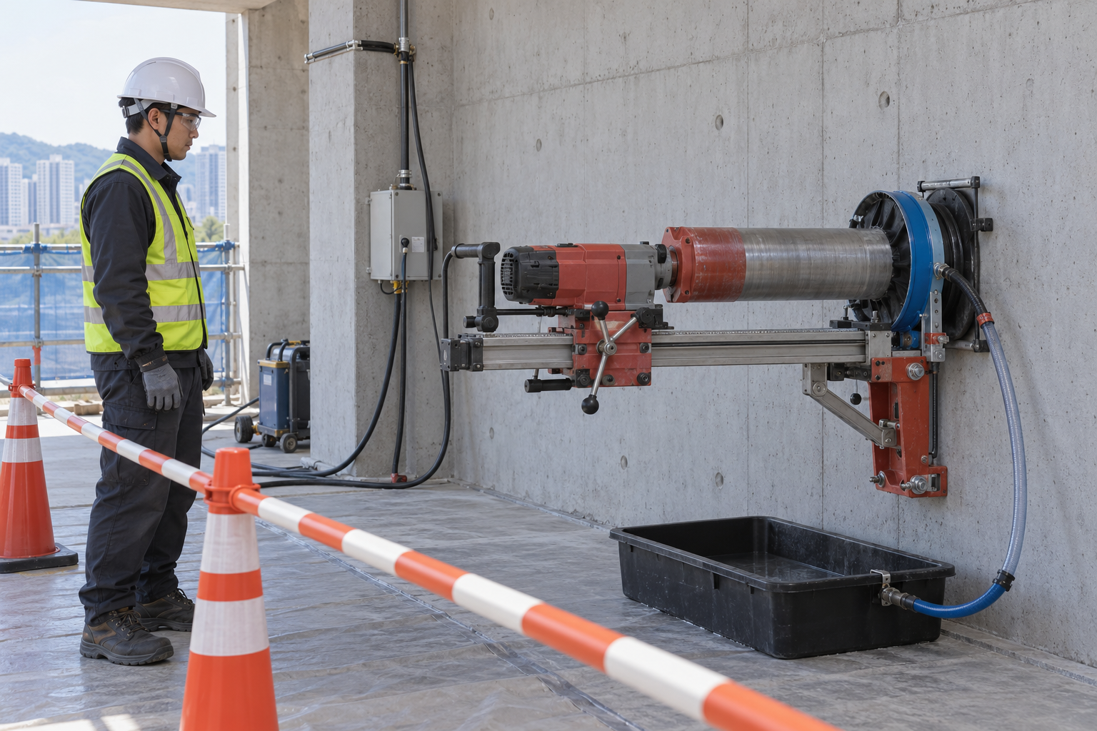 Retained source illustration: an AI-generated educational concept, not a real incident photograph or evidence of equipment suitability.
The following scenario, comparisons and example records are hypothetical teaching material. They do not reproduce actual incidents, measurements, signatures or approvals.
| Item | Hypothetical situation |
|---|---|
| Initial state | Wet drilling begins at an approved wall location. |
| Change | Unexpected metal contact and strong vibration occur at a shallower depth than anticipated. |
| Failure path | The scan record contains an unresolved limitation at that depth. |
| Possible harm | Continuing by feel can damage a service, reinforcement or tensioned element and overload the stand. |
| Barrier | Stop and isolate, record the hole and contact depth, obtain structural and service review and accept any changed position or method before restart. |
Drawings and scanning provide complementary evidence, each with limitations. An empty scan image does not prove that every embedded object is absent. Resolve uncertain depth and material conditions before drilling; the operator must not decide reinforcement or tendon cutting from bit resistance.
The stand transfers drilling reaction to the anchor and substrate. A tight-looking fastener does not establish substrate suitability or anchorage capacity. Check the actual permitted mounting system, base condition, carriage locks and complete travel clearance.
Water must reach the cutting interface and the resulting slurry must be collected. Water at a hose outlet alone proves neither dust control nor electrical protection. Keep electrical connections protected from the water path and verify the specified protective devices before use.
The core and bit can emerge on the opposite side of the wall. Control both sides, provide the planned core support and recovery equipment and wait for complete stop and isolation before handling. Do not rely on a person catching the core by hand.
| Decision | Reason and evidence |
|---|---|
| Known facts | Unexpected metal contact and strong vibration occur at a shallower depth than anticipated. |
| Unresolved | The scan record contains an unresolved limitation at that depth. |
| Hold reason | Do not drill without accepted structural and embedded-service review, access control on both wall faces and a supported stand. Stop for base movement, loss of water or electrical protection, unexpected metal contact or vibration, or failed core containment. |
| Evidence needed | Feed vibration and sound; Base and anchor response; Contact depth and wall position; Water capture and both-side control. |
| Next decision | Stop and isolate, record the hole and contact depth, obtain structural and service review and accept any changed position or method before restart. |
5. Conditional decisions and common errors
| Condition | Action | Evidence | Proceed when |
|---|---|---|---|
| Scan limit unresolved | Hold drilling at that location. | Structural and service review. | Location accepted. |
| Base moves | Stop and isolate. | Substrate anchor and stand assessment. | Support corrected and accepted. |
| Water or protection fails | Stop drilling. | Water capture and electrical checks. | Controls restored. |
| Unexpected metal contact | Record depth and hold. | Object and structural/service review. | Revised scope authorized. |
| Comparison | Situation A | Situation B |
|---|---|---|
| No object visible on scan | Scan limits and structural/service review support the location. | Absence on the display is treated as complete clearance. |
| Water flowing | Cutting-interface supply, slurry capture and electrical protection are verified. | Flow at the hose alone is accepted. |
6. Roles and responsibilities
| Role | Responsibility |
|---|---|
| Work supervisor | Confirm scope, task sequence, exclusion and stop authority. Coordinate approve drilling location with affected operations. |
| Technical reviewer | Resolve the actual design and equipment limits: Coordinates diameter and depth; Wall thickness and scan limits; Structure and service clearance; Approved location and scope. |
| Work crew | Perform anchor and inspect stand using the approved procedure; report any mismatch before proceeding. |
| Inspector / assessor | Verify Breakthrough and drop path; Stopped isolated machine; Core support and tools; Recovery and transport route. Record what was actually checked and what remains unresolved. |
| Release / receiving authority | Confirm Hole size and location; Surrounding damage and service status; Slurry disposal and protection; Receiving trade and open holds. Transfer restrictions and the next permitted stage. |
These are responsibility examples, not invented statutory credentials. Meet the actual training, competent-person, qualified-person and licensing requirements for the assigned work. Anyone may raise a hazard and request a stop; only the designated authority may release the affected stage after evidence is reviewed.
7. Hold points and record comparison
| Hold point | Evidence before release | Confirmation / approval |
|---|---|---|
| HP-0 Start | Scope, jurisdiction, equipment identity, responsible people and emergency arrangements. | |
| HP-1 Control both wall faces | Opposite-side room and owner; Core mass and drop direction; Support and collection route; Both-side access control | |
| HP-2 Anchor and inspect stand | Anchor and substrate evidence; Mounting and fastening basis; Base and carriage stability; Bit stand and travel clearance | |
| HP-3 Set power water and capture | Cord and protection check; Water route and wet zone; Bit water and slurry capture; Floor and ventilation condition | |
| HP-4 Investigate and restart | Contact depth and symptoms; Stand anchor and bit condition; Revised clearance and instructions; Restart evidence and authority |
Hold points are internal evidence gates. They do not replace statutory permits or actual signatures. Recheck affected gates after a change, abnormal event or shift transfer. The blank record must identify the evidence, person, time, limits and release scope.
| Record | Insufficient record | Record checklist |
|---|---|---|
| Location | Scan looks clear | □ Coordinates diameter and depth□ Wall thickness and scan limits□ Structure and service clearance□ Approved location and scope |
| Mounting | Bolt tight | □ Anchor and substrate evidence□ Mounting and fastening basis□ Base and carriage stability□ Bit stand and travel clearance |
| Drilling | Water on | □ Feed vibration and sound□ Base and anchor response□ Contact depth and wall position□ Water capture and both-side control |
| Restart | Base retightened | □ Contact depth and symptoms□ Stand anchor and bit condition□ Revised clearance and instructions□ Restart evidence and authority |
The □ boxes are static prompts, not saved or interactive approvals. Each checks one record element. A tick alone does not establish suitability or permission to restart. Link equipment IDs and supporting records; retain unresolved matters and the earlier record when conditions change.
8. Site checklist and emergency response
| Check item | Result | Person / action |
|---|---|---|
| Coordinates diameter and depth | ||
| Opposite-side room and owner | ||
| Anchor and substrate evidence | ||
| Cord and protection check | ||
| Feed vibration and sound | ||
| Breakthrough and drop path | ||
| Contact depth and symptoms | ||
| Hole size and location | ||
| Emergency arrangements and unresolved restrictions communicated |
Stop work: Do not drill without accepted structural and embedded-service review, access control on both wall faces and a supported stand. Stop for base movement, loss of water or electrical protection, unexpected metal contact or vibration, or failed core containment.
Emergency response: Stop from a safe location and control both wall faces after shock, service damage, flooding or core release. Keep away from suspected energized or gas services, notify the service owner and call 911 for immediate danger or serious injury. Do not restart or improvise a repair before the affected systems are made safe.
9. Sources and review limits
Official-source review date: October 14, 2026. The following review is limited to the public provisions or selected manufacturer material identified below. It does not establish that any authority approved this article or the actual installation.
- OSHA 1926.1153: Table 1 item (vi), full implementation requirement and alternative exposure-control framework.
- OSHA 3929: Rig-Mounted Core Saws or Drills: December 2017 fact sheet: water at the cutting surface, slurry management, enclosed-area ventilation and electrical precautions.
- OSHA 1926.404: Applicable construction wiring and ground-fault protection provisions; actual supply and site program determine scope.
- Hilti DD 150-U (03) instructions: indexed safety excerpt: Official indexed excerpt reviewed for anchor/substrate suitability and opposite-side protection. Full PDF retrieval was unavailable; obtain the current manual for the actual machine before work.
- OSHA State Plans: jurisdiction and coverage overview; identify the actual state program before use.
Paid consensus standards and site-specific calculations, manuals, inspection records and product certificates were not independently obtained or verified unless specifically identified. Korean legal citations remain in the preserved Korean source as source history; they are not represented as US legal duties.
10. PDF guidance and FAQ
PDF A covers basic task controls; B examines technical failures; C focuses on supervision, evidence and handover. Each has six rows and three items per main cell. They are complementary extracts: apply all eight body stages and the applicable site procedure. An omitted stage is not permission to omit its controls. PDF HP-0 through HP-4 are worksheet labels; match the event, evidence and authority rather than assuming they match another permit by number.
P/S/R/A, actual measurements, confirmations and signatures remain blank. The PDFs are uncompleted reference worksheets, not issued work permits.
Content group ID: jsa-wet-wall-core-drilling
Does an empty scan image authorize drilling?
No. Resolve the scan limitations and obtain the required structural and service review.
Can drilling continue through unexpected metal?
Stop and isolate. The responsible structural and service personnel must identify it and determine the permitted scope.
Is vacuum-only mounting covered?
No. This scope requires accepted mechanical anchorage; other methods need separate review.
Does wet drilling always eliminate respirator requirements?
No. Table 1 item (vi) specifies no respirator for the listed task when its controls are fully and properly implemented; other methods, exposures or incomplete controls require the applicable assessment and protection.
Has a professional verified or approved this document?
No. This is AI-assisted reference material. Editorial and layout checks are not a physical inspection or professional technical approval. Obtain qualified professional review and required site approval before use.
11. Revision history and authorship
Reference content written and revised with AI. It has not been verified or approved by a professional. Review by a suitably qualified professional and site approval are required before use.
This system has not physically inspected the equipment, structures, ground, atmosphere or worksite. The document does not replace legal advice, manufacturer procedures, engineering design, inspection certificates, qualification evidence, the site risk assessment or an actual work permit.
Before use, a suitably qualified and authorized person must review the actual equipment, loads, methods, protection, inspection and emergency arrangements and resolve open issues. Record the real reviewer, organization, qualifications, delegated authority, reviewed documents, date, signature, exclusions and conditions of approval separately.
| Date | Version | Change | Review status |
|---|---|---|---|
| 2026-09-25 | 1.0 | Korean source revision retained in the source snapshot. | Historical editorial status; not US professional approval. |
| 2026-10-14 | US 1.0 | US localization of the assigned Korean source; task reasoning, educational image and history retained; US scope and sources reviewed. | AI-assisted editorial work; professional approval not performed. |