An open primary breaker does not exclude secondary backfeed. Trace both sides, standby generation, auxiliary supplies and automatic controls before releasing a connection task.
This is reference content written and revised with AI. It has not been verified or approved by a professional. Review by a suitably qualified professional and required site authorization are necessary before use.
Stop conditions first
Hold access for unknown sources, unverified deenergization/grounding, unsafe lifting/support, bushing strain, connection discrepancy, failed inspection or unaccounted test leads and temporary grounds.
1. US legal and technical basis
Construction installation within applicable OSHA Subpart K electrical scope, including 1926.416 and 1926.417. Electric-power transmission/distribution work under Subpart V and general-industry servicing require separate scope determinations.
| Reference | Use and limit |
|---|---|
| OSHA 29 CFR 1926.416 | Selected electrical-contact protection, circuit identification and protected workspace requirements. |
| OSHA 29 CFR 1926.417 | Deactivated controls and deenergized circuits rendered inoperative and tagged at energization points; apply the complete site safe-work procedure. |
| Eaton MN202001EN, August 2015 | Selected handling/mounting, deenergized wire connection and tap-change warnings. Liquid-filled pad-mounted model reference only; no generic lifting angle, torque, tilt or test values adopted. |
| OSHA State Plans | Federal baseline and State Plan coverage reviewed. Confirm the applicable state program and employer coverage; this edition does not establish nationwide compliance. |
Determine whether Federal OSHA or an applicable State Plan governs the employer and work. Standards incorporated into a regulation must be read in their legally applicable edition. Other NFPA/ANSI guidance and manufacturer instructions have distinct roles; they are not automatically federal law.
2. Scope and required inputs
Included
Receive, position and secure a new transformer; make deenergized primary, secondary and grounding connections; inspect and hand over to a separately controlled testing and energization process.
Separate assessment
Live connection, unapproved tap changes, parallel operation, internal operating-unit inspection, oil processing and performance of electrical testing or energization are outside this installation release.
| Input | Evidence needed |
|---|---|
| Plan nameplate and sources | Nameplate/drawing; Source and feed inventory; Standby/auxiliary controls; Scope/qualified personnel |
| Receive and position | Weight/rigging data; Base and route capacity; Landing/clearance; Transport condition |
| Prepare cables and terminals | Support/bend condition; Bushing external forces; Lug/crimp data; Cleanliness/insulation |
| Hand over for energization | Lead/ground inventory; Configuration/test dossier; People/covers clear; Defects and receiving authority |
Selected public official provisions were checked on October 14, 2026. This is not a complete legal audit. No actual equipment manual, site measurements, engineering calculations, product certification or professional technical approval was supplied. Full paid NFPA/ANSI standards and state/local amendments were not reviewed. Check actual equipment, jurisdiction and project requirements before use.
Select task-appropriate eye, hand, foot, skin and hearing protection from the exposure assessment. Where respiratory protection is necessary, use the applicable respiratory-protection program; PPE does not replace isolation, guarding, support or ventilation.
3. Eight-stage JSA
| Job stage | Hazards and effects | Failure factors | Controls | Site verification | P | S | R | A |
|---|---|---|---|---|---|---|---|---|
| 1. Plan nameplate and sources | 1. Wrong voltage connection2. Secondary backfeed3. Unexpected automatic start4. Wrong unit installed | 1. Diagram outdated2. Generator missed3. Controls untraced4. Nameplate not compared | 1. Compare all system sources2. Trace both transformer sides3. Control automatic starts4. Match unit and design | 1. Nameplate/drawing2. Source and feed inventory3. Standby/auxiliary controls4. Scope/qualified personnel | ||||
| 2. Receive and position | 1. Dropped transformer2. Foundation failure3. Crush at landing4. Unit damage | 1. Weight/lug unknown2. Bearing unverified3. People at pinch point4. Wrong handling point | 1. Use unit-specific lift plan2. Verify route and base3. Exclude landing zone4. Use designated handling points | 1. Weight/rigging data2. Base and route capacity3. Landing/clearance4. Transport condition | ||||
| 3. Isolate and verify | 1. Electric shock2. Arc injury3. Stored-charge contact4. Adjacent live contact | 1. Primary only isolated2. Restart possible3. Discharge omitted4. Work boundary unclear | 1. Isolate relevant sources2. Render inoperative and tag3. Verify/discharge/ground by plan4. Protect adjacent hazards | 1. Isolation points/controls2. Proven instrument results3. Discharge/ground state4. Work boundary authorization | ||||
| 4. Prepare cables and terminals | 1. Bushing fracture2. Cable insulation damage3. Wrong terminal fit4. Contamination fault | 1. Cable weight unsupported2. Bend forced3. Lug incompatible4. Moisture/debris present | 1. Support cables independently2. Align without strain3. Match conductor and lug4. Keep connections clean/dry | 1. Support/bend condition2. Bushing external forces3. Lug/crimp data4. Cleanliness/insulation | ||||
| 5. Connect and fasten | 1. Phase/configuration fault2. Loose hot connection3. Bushing damage4. Grounding defect | 1. Identification wrong2. Torque guessed3. Connection forced4. Neutral/ground confused | 1. Verify phase and winding plan2. Use specified fastening3. Control external cable force4. Check grounding arrangement | 1. Phase/tap/diagram2. Crimp/torque evidence3. Bushing condition4. Ground/neutral continuity | ||||
| 6. Inspect deenergized unit | 1. Insulation failure2. Oil leak/fire exposure3. Overheating4. Object left inside | 1. Clearance missed2. Seal damage ignored3. Vent blocked4. Tool count absent | 1. Inspect insulation/clearance2. Check type-specific condition3. Keep required ventilation4. Reconcile tools/covers | 1. Clearance/insulation2. Liquid/leak controls3. Dry-type ventilation4. Tools/covers record | ||||
| 7. Control test and rework | 1. Test-voltage shock2. Residual charge3. Wrong test circuit4. Unexpected reenergization | 1. Installation release overused2. Discharge omitted3. Components not protected4. Rework without isolation | 1. Require separate test control2. Verify safe post-test state3. Follow unit test procedure4. Re-isolate before rework | 1. Test scope and authority2. Discharge/reverification3. Circuit/instrument criteria4. Rework boundary | ||||
| 8. Hand over for energization | 1. Energized with grounds2. Wrong tap/phase3. Person still exposed4. Unresolved defect used | 1. Inventory incomplete2. Checks not reconciled3. People not cleared4. Release assumed | 1. Reconcile leads and grounds2. Review configuration/tests3. Clear and secure work zone4. Require separate operation release | 1. Lead/ground inventory2. Configuration/test dossier3. People/covers clear4. Defects and receiving authority |
Actual risk assessments, measurements, checks, approvals and signatures have not been performed. Keep unverified fields blank and link the actual site records. P/S/R/A mean likelihood, severity, site-method risk and site-defined acceptance/authorization; a score cannot waive a required control.
4. Failure mechanisms and hypothetical case
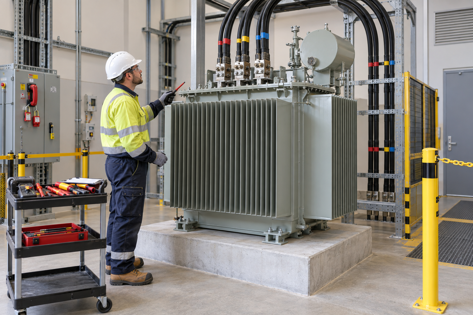
The retained illustration is an AI-generated educational image from the retained source edition. It is not an actual incident photograph, approved drawing, equipment certification or proof that the depicted arrangement is safe.
Identify all primary, secondary, standby and auxiliary sources and prevent unintended energization. Qualified personnel verify the actual work-point state with suitable proven instruments and the applicable discharge/grounding procedure. An open-position indication alone is insufficient.
Terminal torque does not prove that a bushing is free from cable weight, bend force or installation strain. Support cables independently, align connections and inspect each bushing and connection using the actual transformer instructions.
A good insulation result addresses its defined test circuit and conditions. It does not replace phase/vector relationship, tap, protection, grounding, clearance, leak or ventilation checks. Testing creates a different energy state and requires its own exclusion and post-test discharge/reverification.
Temporary grounds and test leads require a controlled inventory and sequence. Do not remove all grounds merely because a test ends or energize with unaccounted connections. Installation completion, test acceptance and operational release remain separate.
Hypothetical decision example
Hypothetical example: primary isolation is recorded, but a standby generator path on the secondary and its automatic start state are unresolved. Keep the connection boundary closed until all sources, controls, work-point verification and required protective grounding are established.
The example is fictional; no incident, measurement, inspection or approval is asserted.
Task flow: Plan nameplate and sources → Receive and position → Isolate and verify → Prepare cables and terminals → Connect and fasten → Inspect deenergized unit → Control test and rework → Hand over for energization
5. Hold and proceed decisions
| Condition | Action | Evidence | Proceed when |
|---|---|---|---|
| Secondary source unknown | Hold access; trace all feeds | Drawings and isolation evidence | Safe state verified |
| Cable strains bushing | Hold connection acceptance | Support/alignment inspection | External force resolved |
| Connection differs | Resolve drawing discrepancy | Phase/tap/ground records | Configuration accepted |
| Test handover incomplete | Keep installation on hold | Lead/ground/people inventory | Separate release issued |
Similar observation, different conclusion
| Observation | Supported conclusion | What remains unresolved |
|---|---|---|
| Primary breaker open | Primary switching state indicated | Secondary/auxiliary feeds unresolved |
| Torque recorded | Specified fastening documented | Cable support and bushing condition unproved |
6. Roles and supervision
| Role | Responsibility |
|---|---|
| Work supervisor | Coordinate plan nameplate and sources, affected operations, stop signals and stage transitions. |
| Technical/equipment reviewer | Verify Nameplate/drawing, Source and feed inventory, actual instructions and unresolved technical limits. |
| Task crew | Apply the stated controls, report changes and keep actual checks and signatures factual. |
| Inspector/test lead | Connect Clearance/insulation, Liquid/leak controls to the required acceptance criteria. |
| Receiving authority | Accept the recorded restrictions, People/covers clear, Defects and receiving authority, and follow-up ownership. |
These are responsibility examples, not invented statutory credentials. Verify actual competence, training and authority for the assigned work.
Supervision and handover controls
| Stage | Management controls | Evidence |
|---|---|---|
| Plan review | 1. Assign technical owner2. Close task-specific questions3. Compare all system sources | 1. Nameplate/drawing2. Source and feed inventory3. Scope/qualified personnel |
| Competence | 1. Verify required competence2. Assign stop authority3. Use unit-specific lift plan | 1. Weight/rigging data2. Training and task briefing3. Transport condition |
| Prestart evidence | 1. Inspect actual equipment2. Link evidence to this stage3. Support cables independently | 1. Support/bend condition2. Bushing external forces3. Cleanliness/insulation |
| Change control | 1. Stop and secure the area2. Review affected controls3. Require separate test control | 1. Test scope and authority2. Discharge/reverification3. Rework boundary |
| Shift handover | 1. Identify remaining restrictions2. Confirm receiving responsibility3. Reconcile leads and grounds | 1. Lead/ground inventory2. Configuration/test dossier3. Defects and receiving authority |
| Closeout | 1. Record defect disposition2. Archive factual evidence3. Reconcile leads and grounds | 1. Lead/ground inventory2. Configuration/test dossier3. Defects and receiving authority |
7. Hold points and record quality
| Hold point | Evidence before release | Actual record |
|---|---|---|
| HP-0 Start | Receive, position and secure a new transformer; make deenergized primary, secondary and grounding connections; inspect and hand over to a separately controlled testing and energization process. | |
| HP-1 Receive and position | Weight/rigging data; Base and route capacity; Landing/clearance; Transport condition | |
| HP-2 Prepare cables and terminals | Support/bend condition; Bushing external forces; Lug/crimp data; Cleanliness/insulation | |
| HP-3 Control test and rework | Test scope and authority; Discharge/reverification; Circuit/instrument criteria; Rework boundary | |
| HP-4 Hand over for energization | Lead/ground inventory; Configuration/test dossier; People/covers clear; Defects and receiving authority |
Hold points are internal evidence gates. They do not establish that a statutory permit exists or has been approved. Recheck affected gates after changes, faults and shift handover.
Record comparison - hypothetical templates
The 16 boxes below identify record elements, not completed checks or approvals. They are static symbols. Link equipment/location, date, actual findings and the separate record reference; preserve unresolved items.
| Record | Insufficient entry | Required record elements |
|---|---|---|
| Plan nameplate and sources | "Checked" without supporting facts | □ Nameplate/drawing□ Source and feed inventory□ Standby/auxiliary controls□ Scope/qualified personnel |
| Isolate and verify | "Checked" without supporting facts | □ Isolation points/controls□ Proven instrument results□ Discharge/ground state□ Work boundary authorization |
| Connect and fasten | "Checked" without supporting facts | □ Phase/tap/diagram□ Crimp/torque evidence□ Bushing condition□ Ground/neutral continuity |
| Control test and rework | "Checked" without supporting facts | □ Test scope and authority□ Discharge/reverification□ Circuit/instrument criteria□ Rework boundary |
8. Pre-work checks and emergency response
| Check required | Result | Checker/action |
|---|---|---|
| Plan nameplate and sources: Nameplate/drawing | ||
| Receive and position: Weight/rigging data | ||
| Isolate and verify: Isolation points/controls | ||
| Prepare cables and terminals: Support/bend condition | ||
| Connect and fasten: Phase/tap/diagram | ||
| Inspect deenergized unit: Clearance/insulation | ||
| Control test and rework: Test scope and authority | ||
| Hand over for energization: Lead/ground inventory |
Stop work
Hold access for unknown sources, unverified deenergization/grounding, unsafe lifting/support, bushing strain, connection discrepancy, failed inspection or unaccounted test leads and temporary grounds.
Emergency response
Keep clear of suspected energized equipment, fallen conductors, unstable loads and leaking/fire-affected transformers. Isolate remotely only when authorized and safe, restrict access and call the site electrical emergency team and 911 for serious injury or fire. Do not touch an electrical casualty until the energy hazard is controlled. Trained responders handle electrical rescue, fire and spill hazards using the unit type and site plan.
9. Official sources and review limits
Official public-source check: October 14, 2026. The review concerns the selected passages described below, not endorsement of this article.
| Official source | Checked scope and limit |
|---|---|
| OSHA 29 CFR 1926.416 | Selected electrical-contact protection, circuit identification and protected workspace requirements. |
| OSHA 29 CFR 1926.417 | Deactivated controls and deenergized circuits rendered inoperative and tagged at energization points; apply the complete site safe-work procedure. |
| Eaton MN202001EN, August 2015 | Selected handling/mounting, deenergized wire connection and tap-change warnings. Liquid-filled pad-mounted model reference only; no generic lifting angle, torque, tilt or test values adopted. |
| OSHA State Plans | Federal baseline and State Plan coverage reviewed. Confirm the applicable state program and employer coverage; this edition does not establish nationwide compliance. |
Selected public official provisions were checked on October 14, 2026. This is not a complete legal audit. No actual equipment manual, site measurements, engineering calculations, product certification or professional technical approval was supplied. Full paid NFPA/ANSI standards and state/local amendments were not reviewed. Check actual equipment, jurisdiction and project requirements before use.
This is reference content written and revised with AI. It has not been verified or approved by a professional. Review by a suitably qualified professional and required site authorization are necessary before use.
10. PDF use and frequently asked questions
PDF A summarizes core controls; B emphasizes technical failures; C covers supervision, records and handover. Each uses six stages from or aligned with the eight-stage body. All actual risk, measurement, check and signature fields are blank. Use a separate linked record where more space is needed.
Does primary isolation permit connection work?
Only after every relevant source and the actual work-point safe state have been verified.
Can oil-filled transformer values apply to dry types?
No. Use the exact unit and component instructions.
Does one good test result authorize energization?
No. Complete the required configuration, condition and separate release checks.
When are temporary grounds removed?
Only through the approved protective-state and restoration sequence by authorized personnel.
Has a professional approved this JSA?
This is reference content written and revised with AI. It has not been verified or approved by a professional. Review by a suitably qualified professional and required site authorization are necessary before use.
11. Authorship and revision history
This is reference content written and revised with AI. It has not been verified or approved by a professional. Review by a suitably qualified professional and required site authorization are necessary before use.
| Date/version | Editorial history | Technical approval |
|---|---|---|
| September 19, 2026 / Korean v1.1 | Korean source: retained previously displayed draft version and source-check date; no professional review record asserted. | Professional technical approval not performed |
| September 26, 2026 / Korean v1.2 | Korean source: revised task decisions, record checklists, JSA and three PDFs; editorial/source and layout checks. | Professional technical approval not performed |
| October 14, 2026 / US v1.0 | US localization: Retains secondary-generator backfeed case, independent cable support and separate test/energization decisions. Applies construction electrical scope and selected Eaton model guidance without universal torque, test or lifting values. | Not performed |
Source topic: https://smartjsabridge.com/ko/case-study/jsa-transformer-installation
Content group: jsa-transformer-installation