This is reference content written and revised with AI. It has not been verified or approved by a professional. Review by a suitably qualified professional and site authorisation are required before use.
Revision: the master JSA is organised into eight stages with four prompts in each main cell. Short conditional release criteria and sixteen record prompts separate evidence from approval. Three six-stage PDFs use task, technical-failure and supervision viewpoints; actual evaluation fields remain blank. Valid prior explanations, sources and history are retained. This is an editorial revision, not professional technical verification.
1. Legal and technical scope
Review update, 12 October 2026: the entries below identify the official material rechecked for this revision and its specific scope. Earlier source notes and dates are retained as revision history; they do not mean that every cited provision was reverified today. Full paid standards, actual equipment manuals, site calculations and approvals were not supplied or verified. Resolve their current applicability with a qualified reviewer before use.
| Source | Scope and limitations |
|---|---|
| OSHA — 29 CFR 1926.652 | Protective-system design options, foreseeable loads, secure connections and safe staged installation were reviewed. Required support must be effective before the associated exposure or load. OSHA compliance does not establish the capacity of an unidentified strut. |
A. United States federal baseline
This guide addresses installation of steel wales, corbels or brackets, and H-beam struts used to support an excavation. “H-beam” is a general description; the approved drawings must identify the actual steel section, material, orientation, and connection details.
The principal federal excavation requirements are OSHA 29 CFR 1926 Subpart P, particularly §§1926.651 and 1926.652. They address excavation conditions, protective systems, and safe installation of support members. A completed JSA does not establish the adequacy of a shoring design.
• Determine whether federal OSHA or an OSHA-approved State Plan governs the employer and work.
• Identify applicable state licensing requirements, local excavation and building requirements, fire permits, and utility notification rules.
• The fictional Chicago example in Section 4 does not establish the jurisdiction of the reader’s project.
B. Engineering basis for the support system
Use a documented design route permitted by §1926.652(c). For a custom multilevel steel bracing system outside applicable tabulated data, obtain approval by a registered professional engineer under §1926.652(c)(4).
• The design must address the actual excavation geometry, ground and groundwater conditions, adjacent foundations, surcharge loads, and construction stages.
• Installation-stage stability requires explicit consideration; an acceptable final arrangement does not establish that partially assembled members are stable.
• Identify the approved excavation sequence, support elevations, connection details, temporary restraints, preload requirements, and monitoring criteria.
• Keep the required design documentation available at the jobsite. Resolve discrepancies before continuing the affected work.
C. Fall protection and steel erection applicability
Do not apply the steel erection provisions solely because steel beams are present. Determine whether the actual activity falls within §1926.750 before using Subpart R requirements.
For work governed by Subpart M, §1926.501(a)(2) requires adequate walking/working-surface strength and integrity. Section 1926.501(b)(1) addresses unprotected working-surface edges at 6 feet or more above a lower level; excavation-edge provisions have their own conditions under §1926.501(b)(7). Walkways crossing excavations are also addressed by §1926.651(l).
• Do not transplant a steel erection fall-protection threshold into excavation work without establishing applicability.
• Apply the provisions governing the selected scaffold, aerial lift, walkway, or other access system.
• This guide adopts a project control prohibiting unsecured struts from being used as access routes. It does not claim that OSHA requires a MEWP for every connection.
D. Lifting, hot work, and atmospheric hazards
Apply the relevant crane provisions of Subpart CC and rigging requirements of §1926.251. Section 1926.1425 restricts personnel in the load fall zone and requires qualified rigging for the specified activities. Section 1926.651(e) prohibits employees underneath loads handled by lifting or digging equipment.
Sections 1926.352 and 1926.353 govern fire prevention and welding ventilation/protection. Fire-watch duties depend on the conditions identified in §1926.352(e); respirator selection depends on the process, materials, atmosphere, and applicable respiratory protection requirements.
Construction work regulated by Subpart P is excluded from Subpart AA under §1926.1201(b)(1). That exception does not remove excavation atmospheric precautions or applicable welding requirements. Separate entry into a manhole, tank, or other space requires a separate assessment.
E. Technical standards and their legal status
The engineer must identify the standards and editions applicable to the actual design and contract. Potential references include ANSI/AISC 360-22, Specification for Structural Steel Buildings, and AWS D1.1/D1.1M for structural steel welding where their scopes and project adoption apply.
• AISC identifies ANSI/AISC 360-22 and lists January 2025 errata for its first printing.
• AWS currently lists AWS D1.1/D1.1M:2025-AMD1, Structural Welding Code—Steel.
• These publisher listings do not establish which edition governs a particular project. Adoption by law, contract, or approved design must be checked.
• Publisher information was checked; this article does not claim a clause-by-clause review of the full AISC specification or AWS welding code.
F. JSA/JHA and permit-to-work status
“Job Safety Analysis” and “Job Hazard Analysis” are commonly used planning terms in the United States. This guide’s high-risk work permit is a proposed project authorization process, not a claim that Subpart P mandates a nationwide permit form with that title.
Identify any legally required permits separately, including applicable local hot-work or excavation permits and any entry permit required for a separately assessed permit-required confined space.
A JSA, JHA, risk score, or permit cannot replace or waive legal requirements, manufacturer restrictions, engineering responsibilities, inspections, or hold points.
2. Scope and required inputs
A. Included work
This guide covers receipt and unloading of support steel; verification of the existing support interface; installation of corbels, wales, and struts; temporary restraint; bolting and welding; hydraulic preloading where specified; access facilities; and handover.
It assumes an approved method maintains excavation stability and worker protection at every stage. It does not authorize entering an unsupported excavation to install its first protective system.
• Soldier-pile driving or drilling, tieback installation, underpinning, and major dewatering installation require task-specific assessments.
• Removal, unloading, or relocation of installed struts requires a separate engineered sequence and authorization.
• Welding, preload application, connection completion, and crane release must follow the approved project sequence; their exact order cannot be standardized for every system.
B. Required project package
The site team should assemble and verify the following before releasing the relevant hold points.
• Applicable jurisdiction, employer coverage, permits, and approved work boundaries.
• Geotechnical information and the current shoring drawings, calculations, revisions, and design responsibilities.
• Member schedule, steel identification, connection details, temporary bracing, and acceptance criteria.
• Lift plan, verified member weights, rigging arrangement, equipment configuration, and ground-support assessment.
• Safe access and fall-protection arrangements, including any designated anchors and rescue provisions.
• Jack, pump, hose, fitting, gauge, and load-measurement documentation for the actual equipment.
• Approved preload sequence, force targets, movement limits, lock-off method, and stop criteria.
• Welding procedures, welder qualification records, inspection requirements, and bolting installation instructions.
• Atmospheric assessment, hot-work controls, emergency arrangements, and monitoring plan.
• Personnel qualification, training, employer authorization, and inspection records applicable to each role.
C. Missing information
No project location, equipment model, member schedule, shoring calculation, or signed engineering review was supplied with the source article. This guide therefore provides no project-specific wind limit, preload force, torque, weld size, anchor capacity, or exclusion-zone dimension.
3. Eight-stage JSA
| Job stage | Hazards and effects | Failure factors | Technical and procedural controls | Site verification | P | S | R | A |
|---|---|---|---|---|---|---|---|---|
| 1. Plan and ground | 1. Ground collapse2. Water or base failure3. Service strike4. Adjacent settlement | 1. Wrong ground model2. Excavation too deep3. Unknown services4. Surcharge omitted | 1. Check staged design2. Verify ground and water3. Locate and protect services4. Set monitoring triggers | 1. Design and stage revision2. Ground and water record3. Service clearance4. Baseline and triggers | ||||
| 2. Lift and access | 1. Dropped steel2. Crane or platform overturns3. Fall from access4. Crushing by load | 1. Wrong mass or rigging2. Weak plant support3. Unreachable sling release4. Shared lifting zone | 1. Verify actual lift setup2. Provide checked plant base3. Plan protected access4. Exclude load movement zone | 1. Mass and rigging check2. Plant support assessment3. Access and rescue plan4. Signalling and exclusion | ||||
| 3. Seats and walers | 1. Falling bracket2. Waler rotation3. Weld burn or fire4. Wall connection failure | 1. Wrong bearing detail2. Early hook release3. Uncontrolled hot work4. Unapproved attachment | 1. Match seats to design2. Secure before hook release3. Apply hot-work controls4. Inspect required connections | 1. Seat and bearing check2. Erection release record3. Hot-work and fume controls4. Weld and bolt evidence | ||||
| 4. Place struts | 1. Strut rolls or slips2. Hand crushed at joint3. Fall from bare beam4. Temporary instability | 1. Missing erection restraint2. Hands in bolt holes3. No protected work position4. Wrong member or length | 1. Fit designed restraints2. Use alignment tools3. Keep off bare flanges4. Verify member and seating | 1. Member identification2. Restraint inspection3. Protected access check4. Load-transfer release | ||||
| 5. Connect and brace | 1. Member buckling2. Connection failure3. Dropped tools4. Welding fume exposure | 1. Brace has no load path2. Wrong bolt or weld3. Tools unsecured4. Poor source extraction | 1. Complete load-path details2. Apply connection procedure3. Secure tools and lower zone4. Control fumes at source | 1. Brace and reaction check2. Bolt and weld acceptance3. Tool and zone check4. Exposure-control evidence | ||||
| 6. Preload and lock | 1. Jack or plate ejects2. Hydraulic injection3. Support overload4. Load lost at lock-off | 1. Eccentric jack reaction2. Damaged pressure line3. Wrong force conversion4. Unverified retaining system | 1. Use engineered procedure2. Keep clear of release paths3. Monitor force and movement4. Verify retained load transfer | 1. Jack and gauge records2. Preload and movement log3. Lock-off acceptance4. Leak and pressure checks | ||||
| 7. Inspect and access | 1. Unaccepted support loaded2. Fall from walkway3. Added load overstresses strut4. Unresolved defect | 1. Inspection incomplete2. Missing edge protection3. Walkway load omitted4. Paint mark treated as proof | 1. Close stage defects2. Check walkway and guards3. Verify added loads by design4. Record acceptance evidence | 1. As-built support record2. Walkway and guard check3. Added-load approval basis4. Closed inspection issues | ||||
| 8. Handover and monitor | 1. Next excavation collapses2. Movement goes unnoticed3. Unsafe alteration4. Rescuer exposed | 1. Stage not released2. Monitoring unavailable3. Strut removed for access4. Rescue improvised | 1. Release next stage explicitly2. Maintain trigger response3. Control all support changes4. Use planned protected rescue | 1. Stage and limits handover2. Monitoring status3. Change-control record4. Emergency readiness |
PDF A covers basic task controls; B focuses on technical failures; C covers supervision, records and handover. The article has eight stages with four items per main cell; each PDF has six key stages with three items per main cell. P/S/R/A, measurements, confirmations and signatures remain blank for actual site assessment.
4. Fictional scenario and failure mechanisms
A. Simulation notice
The following case is a hypothetical simulation for training and risk assessment. It does not represent an actual accident, a government investigation, or an incident involving a particular company.
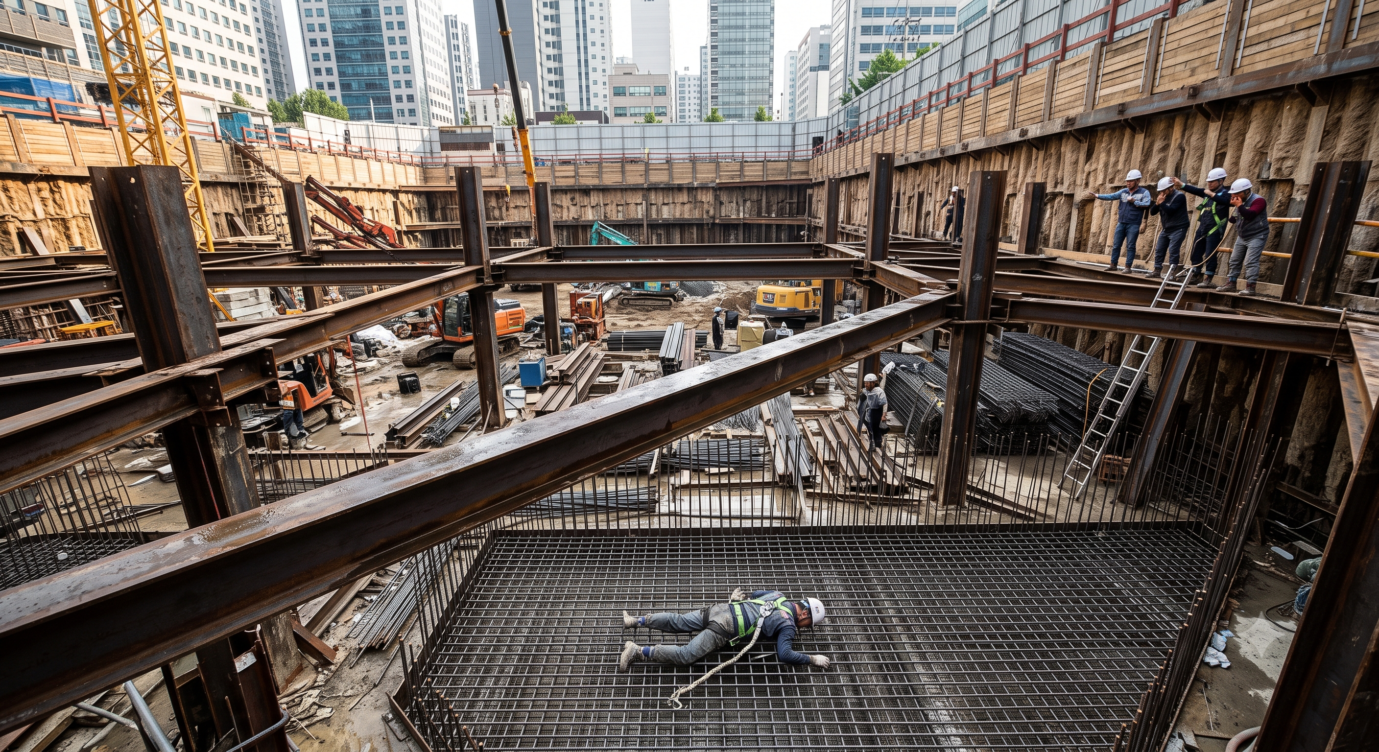
The original image URL is retained. The illustration is not evidence of an accident, an accurate representation of a particular support system, or an approved work method.
B. Initial conditions
In a fictional Chicago high-rise foundation project, a crew is installing a third level of steel struts. The potential fall distance from the work position to a lower concrete surface is approximately 40 feet; this is a scenario assumption, not a regulatory threshold.
A crawler crane has positioned a strut between wales. Initial attachment has been made, but the installation-stage restraint and connection acceptance have not been confirmed. A MEWP is available, although its positioning and access to the rigging-release point have not been fully coordinated.
C. Weather and task changes
Overnight moisture has left the upper flange slippery. The crew encounters an access delay and attempts to complete the rigging release before the planned protected route is ready.
The example does not assume that a specific wind speed caused the event. Any wind restriction would have to come from the actual lifting and access equipment, load configuration, and approved work plan.
D. Unsafe transition and possible failure sequence
A worker leaves the protected access arrangement, disconnects the personal fall-protection system, and steps onto the newly installed strut.
• The narrow, wet flange provides a poor walking surface.
• The worker’s movement introduces an unintended local and potentially eccentric load.
• Depending on the actual restraint, the member could rotate or shift; a slip alone could also initiate the fall.
• With no effective fall-prevention or arrest system in that position, the worker could fall to the lower surface and sustain fatal injuries.
No OSHA finding, citation classification, or confirmed equipment defect is attributed to this fictional event.
E. Structural and mechanical analysis
A wale transfers reactions along the retaining system; a strut generally carries compression between its support points. The actual load path depends on the design, including intermediate supports, splices, end restraint, and construction stage.
Installation-stage stability
• Before the specified restraints and connections are effective, the assembly may not behave like the completed design model.
• A loosely connected member may be vulnerable to rotation, displacement, or loss of bearing.
• A worker’s weight does not prove that a correctly designed strut would fail, but personnel access can introduce loading that was not allowed for that temporary stage.
Compression and restraint
• Buckling resistance depends on section properties, effective unbraced length, end conditions, imperfections, and applied load.
• Two members crossing in plan do not automatically brace each other. Any credited restraint requires adequate stiffness, strength, and connection to a suitable load path.
• Arbitrarily adding U-bolts or clamps may create unintended forces or local damage and does not establish effective bracing.
Hydraulic preload
• Preloading stores elastic energy in the support system and energy in the pressurized hydraulic circuit.
• Loss of bearing, jack movement, hose failure, or connection failure may release that energy rapidly and produce member movement.
• Hydraulic pressure alone does not demonstrate the actual retained strut force or the integrity of the completed load path.
Without calculations, equipment data, measurements, and physical evidence, these mechanisms remain plausible hypotheses. No specific failure load, causal sequence, or structural defect is established by this simulation.
F. Failed protective barriers
| Protective Barrier | Failure in the Simulation | Potential Effect | Required Improvement |
|---|---|---|---|
| Planned access |
|
|
|
| Installation-stage restraint |
|
|
|
| Fall protection |
|
|
|
| Surface condition |
|
|
|
| Hold-point control |
|
|
|
G. Key lessons
Safe access must be designed into the installation sequence. Temporary attachment, final structural acceptance, crane release, and permission for personnel access are different decisions. None should be inferred from the appearance of a seated beam or from completion of a JSA.
5. Conditional decisions and common errors
| Condition | Action | Evidence | Proceed when |
|---|---|---|---|
| Rain or seepage changes | Hold the affected excavation; assess drainage and support response. | Water observations, movement trends and engineering disposition. | Water and support conditions accepted. |
| Rigging point unreachable | Stop unhooking; revise the protected access and lifting arrangement. | Access reach check, support assessment and lifting-team briefing. | Protected access and stable seating confirmed. |
| Unexpected preload response | Keep people clear; obtain the engineered response without uncontrolled unloading. | Force/movement log, equipment checks and revised load-transfer instruction. | Cause resolved; load retention accepted. |
| Next excavation stage | Close support defects and check monitoring before releasing the next cut. | As-built acceptance, stage drawing and current monitoring. | Required support accepted; monitoring active. |
A. Maintain a verified load path
Specify the condition required before each load transfer: receiving support, bearing, connections, temporary restraint, and any instrumentation checks. Do not substitute a blanket “fully welded” instruction for the actual bolted, welded, bearing, or proprietary connection detail.
• Do not field-cut, drill, heat-straighten, weld to, or relocate a loaded member without the required engineering review.
• Do not install temporary bolts, packing, or jack reactions from improvised details.
• Do not treat survey level, paint marks, or pressure readings as standalone proof of structural adequacy.
B. Control lifting and equipment interaction
The crane setup, operating radius, load configuration, ground support, and nearby excavation surcharge must be compatible.
• Establish the load fall zone and swing/crush controls from the actual operation; no universal exclusion radius is specified here.
• Restrict receiving and connection personnel as required by the applicable lifting provisions.
• Use manufacturer operating limits and the lift-specific assessment for wind and other weather conditions. General crane operating limits do not automatically authorize handling a particular long beam.
• A permit cannot authorize exceeding equipment limits.
C. Control hydraulic energy
Use only the approved preload and load-transfer procedure. The engineer must define the force target, acceptable response, required measurement method, and disposition of unexpected results.
• Pressure-to-force conversion must match the actual jack and setup, including relevant calibration and system effects.
• Consider lateral buckling and ejection hazards as well as the jack’s axial line of force.
• Keep personnel clear during loading; do not tighten fittings or reposition bearing components under pressure.
• Do not search for a high-pressure leak with a hand. Isolate and release energy through the manufacturer’s procedure before maintenance.
• Do not prescribe an improvised proof test, emergency release, or sudden depressurization as a general response.
D. Control hot work, fumes, and emergency access
Assess the base metal, coatings, consumables, welding process, ventilation, and nearby workers. An ordinary gas monitor does not measure every welding fume exposure.
• Apply §1926.353(b) where welding occurs in a confined space and §1926.353(c) where specified toxic metals or coatings are involved. Do not assume that open-air work removes all respiratory requirements.
• Select respiratory protection through the applicable program, including medical evaluation, fit testing for tight-fitting respirators, and training where required. An air-purifying respirator does not supply oxygen.
• Protect combustible lagging, waterproofing, debris, hoses, and concealed areas from sparks, slag, and heat transfer.
• Assign fire-watch personnel when required by the conditions, governing rules, or project permit. Determine post-work coverage from those requirements rather than inventing a universal duration.
• Maintain emergency access and task-specific fall, atmospheric, and excavation rescue arrangements.
E. Stop-work and restart conditions
Stop the affected activity when there is unexpected movement, loss of bearing, abnormal pressure/travel, connection distress, impact damage, unsafe water accumulation, atmospheric alarm, failed access protection, lost lifting communication, or weather outside approved conditions.
Remove exposed personnel from the hazard area. Stabilization, investigation, and restart must follow the appropriate competent-person and engineering decisions; a permit signature alone cannot make the condition safe.
F. Frequently asked questions
Does OSHA require double-choker hitches for every H-beam lift?
No universal double-choker requirement is established by the cited provisions. Select rigging for the member geometry, weight, center of gravity, sling capacity, hitch limitations, edge protection, and planned handling conditions.
Must every shoring connection be installed from a MEWP?
No. Select a compliant access system for the task, such as a suitable MEWP, scaffold, or engineered platform. This guide prohibits using unsecured struts as access routes.
Does a hydraulic pressure reading prove that strut preload is correct?
No. Verification requires the approved relationship between pressure and force for the actual jack arrangement, together with the specified checks of alignment, movement, connections, and load transfer.
Does every deep excavation require a confined-space entry permit?
No. Construction work regulated by OSHA Subpart P is excluded from Subpart AA under §1926.1201(b)(1). Separate entry into a manhole, tank, or other space requires its own applicability assessment. Excavation atmospheric precautions and applicable welding requirements still apply.
Can a JSA or work permit authorize a departure from the shoring design?
No. Neither a JSA, a risk score, nor a work permit replaces applicable legal duties, manufacturer restrictions, engineering approval, required inspections, or unresolved hold points.
6. Roles and responsibilities
A. Employer and site management
Provide the required protective arrangements, competent personnel, equipment, training, coordination, and resources. Define permit authority and prevent simultaneous operations from defeating the shoring or lifting controls.
B. Excavation competent person
Identify existing and predictable hazards and have authority to correct them promptly. Carry out the required excavation inspections and remove exposed workers when unsafe conditions are found. This role does not automatically confer authority to redesign the support system.
C. Responsible shoring engineer
Establish the design basis, construction-stage requirements, connection and preload details, monitoring criteria, and acceptable changes within the engineer’s competence and applicable registration requirements.
D. Crane operator, qualified rigger, and signal person
Keep these functions distinct. Verify crane-operator training, applicable certification/licensing, and employer evaluation. Confirm rigging qualifications for the actual work and signal-person qualifications where required. A training card or general job title does not establish every required competency.
E. Installation, welding, bolting, and inspection personnel
Follow the approved details and work procedures. Verify welder qualifications for the applicable process and work, and assign inspection responsibility under the project requirements. Do not assume that every inspector must hold the same commercial certification.
F. Permit issuer, fire watch, and emergency personnel
The permit issuer verifies release evidence within delegated authority. A fire watch performs the assigned fire-prevention duties without conflicting tasks. Emergency personnel must be prepared for the actual access, fall, atmosphere, and collapse hazards.
Training completion, professional registration, trade qualification, medical clearance where required, employer authorization, and technical approval are separate records and are not interchangeable.
Supervision, records, handover
| Job stage | Technical and procedural controls | Site verification |
|---|---|---|
| Plan ownership | 1. Verify assigned authority2. Check staged design3. Set monitoring triggers | 1. Design and stage revision2. Ground and water record3. Service clearance |
| Team and equipment | 1. Record equipment evidence2. Verify actual lift setup3. Exclude load movement zone | 1. Mass and rigging check2. Plant support assessment3. Access and rescue plan |
| Stage release | 1. Hold stage release2. Fit designed restraints3. Verify member and seating | 1. Member identification2. Restraint inspection3. Protected access check |
| Energy control | 1. Record energy controls2. Use engineered procedure3. Verify retained load transfer | 1. Jack and gauge records2. Preload and movement log3. Lock-off acceptance |
| Inspection closure | 1. Close inspection defects2. Close stage defects3. Record acceptance evidence | 1. As-built support record2. Walkway and guard check3. Added-load approval basis |
| Shift handover | 1. Transmit limits and issues2. Release next stage explicitly3. Use planned protected rescue | 1. Stage and limits handover2. Monitoring status3. Change-control record |
7. Hold points and record comparison
A. Permit identification
The project permit should identify the location, support level, work scope, drawing revision, equipment, crew, validity period, adjacent operations, required supporting permits, and responsible release authorities.
The hold points below are proposed project controls. Their labels are not prescribed OSHA permit categories.
| Hold Point | Evidence Required Before Release | Assigned Release Responsibility |
|---|---|---|
| HP-1: Design and sequence |
|
|
| HP-2: Excavation and access |
|
|
| HP-3: Lift readiness |
|
|
| HP-4: Connection and crane release |
|
|
| HP-5: Preload readiness |
|
|
| HP-6: Load transfer and acceptance |
|
|
| HP-7: Handover and next stage |
|
|
B. Separate hot-work authorization
Before welding or cutting, verify the applicable permit requirements, atmosphere assessment, fire controls, and qualifications. Reassess when work location, materials, ventilation, or surrounding conditions change.
C. Suspension and revalidation
Record each release with the person’s name, role, date, time, evidence, and limitations. Suspend affected authorization following an incident, design change, abnormal monitoring result, or loss of a required control.
Revalidation requires resolution of the actual condition and any required new inspection or engineering review. No role may approve outside its technical competence or delegated authority.
Record comparison examples
The scenario and record comparisons are fictional teaching examples, not records of real incidents, measurements, inspections, signatures or approvals.
The boxes are static record prompts, not interactive or saved approvals. A tick does not establish suitability or permission to restart. Record the evidence, person, time and unresolved issues; retain the change history.
| Record type | Insufficient record | Record checklist |
|---|---|---|
| Plan and ground | “OK” | □ Design and stage revision□ Ground and water record□ Service clearance□ Baseline and triggers |
| Place struts | “OK” | □ Member identification□ Restraint inspection□ Protected access check□ Load-transfer release |
| Preload and lock | “OK” | □ Jack and gauge records□ Preload and movement log□ Lock-off acceptance□ Leak and pressure checks |
| Handover and monitor | “OK” | □ Stage and limits handover□ Monitoring status□ Change-control record□ Emergency readiness |
8. Site checklist and emergency response
A. Design and authorization
• ☐ The applicable jurisdiction and project permits have been identified.
• ☐ The correct drawing revision and support level are available to the crew.
• ☐ Current excavation conditions match the design assumptions or have an approved disposition.
• ☐ Temporary restraint, connection sequence, and crane-release criteria are understood.
• ☐ No unresolved hold point affects the planned task.
B. Excavation and equipment areas
• ☐ The competent person has inspected the excavation before exposure and addressed unsafe findings.
• ☐ Water, ground movement, adjacent structures, and utility interfaces have been assessed.
• ☐ Crane and access-equipment positions match the approved support and surcharge assessment.
• ☐ Materials are controlled against rolling or falling into the excavation.
• ☐ Safe access and emergency routes remain available.
C. Materials, lifting, and access
• ☐ Member identity, condition, connection materials, and intended orientation are correct.
• ☐ Load weight, rigging arrangement, accessory condition, and equipment capacity are verified.
• ☐ Receiving personnel, signals, fall-zone controls, and equipment swing controls are established.
• ☐ Protected access reaches the actual connection and rigging-release positions.
• ☐ Personal fall-protection attachments, clearance, and rescue arrangements are verified where used.
D. Connections and preload
• ☐ Required installation-stage bolts, welds, bearing details, and restraints are accepted.
• ☐ Welding and bolting procedures match the approved connection requirements.
• ☐ Jack, pump, hoses, fittings, and instrumentation are suitable for the actual arrangement.
• ☐ Preload targets, measurement method, load-transfer details, and stop criteria are available.
• ☐ Exclusion areas address axial ejection, lateral movement, and hydraulic failure.
• ☐ No improvised modification, pressure test, or load-transfer method is planned.
E. Hot work and emergency readiness
• ☐ Coatings, metals, welding fumes, and potential atmospheric hazards have been assessed.
• ☐ Required ventilation, monitoring, respiratory protection, and permits are in place.
• ☐ Combustibles and concealed fire paths are controlled; required fire-watch coverage is assigned.
• ☐ Emergency communications, rescue arrangements, and responding personnel are ready.
• ☐ The crew understands stop-work triggers and the restart process.
An unchecked item is not automatically acceptable. Mark an item not applicable only with a documented reason and confirmation by the responsible person.
9. Sources and review limits
Review update, 12 October 2026: the entries below identify the official material rechecked for this revision and its specific scope. Earlier source notes and dates are retained as revision history; they do not mean that every cited provision was reverified today. Full paid standards, actual equipment manuals, site calculations and approvals were not supplied or verified. Resolve their current applicability with a qualified reviewer before use.
| Source | Scope and limitations |
|---|---|
| OSHA — 29 CFR 1926.652 | Protective-system design options, foreseeable loads, secure connections and safe staged installation were reviewed. Required support must be effective before the associated exposure or load. OSHA compliance does not establish the capacity of an unidentified strut. |
A. Federal regulatory sources
The following official sources support the regulatory framework. OSHA provisions are binding where applicable; explanatory guidance and publisher descriptions have different legal status.
| Source | Application and Verification Note |
|---|---|
| eCFR: 29 CFR 1926.652 | Protective-system design routes, condition of components, and support-system installation. The displayed Title 29 consolidation was current through September 16, 2026 when accessed. |
| OSHA: 1926.651 | Excavation conditions, utilities, access, falling loads, atmosphere, water, adjacent structures, inspections, and crossings. |
| OSHA: 1926.652 | Official OSHA presentation of the protective-system requirements, directly reviewed alongside the eCFR text. |
| OSHA: 1926.750 | Scope of steel erection requirements; review before assigning Subpart R duties or thresholds. |
| OSHA: 1926.501 | Fall-protection duties for the activities and conditions addressed by the section. |
| GovInfo: 1926.502, 2025 annual edition | Fall-protection system criteria. This is an annual CFR edition, not evidence by itself of subsequent amendment status. |
| OSHA: 1926.1425 | Hoisting routes, fall-zone restrictions, load receiving, and specified qualified-rigger requirements. |
| GovInfo: 1926.1402, 2025 annual edition | Crane ground conditions and allocation of relevant duties. |
| GovInfo: 1926.1417, 2025 annual edition | Crane operation, manufacturer procedures, and operating conditions. |
| GovInfo: 1926.251, 2025 annual edition | Rigging equipment requirements. |
| GovInfo: 1926.1427, 2025 annual edition | Crane-operator training, certification/licensing, and evaluation, subject to the section’s scope and exceptions. |
| GovInfo: 1926.1428, 2025 annual edition | Signal-person qualifications. |
| GovInfo: 1926.453, 2025 annual edition | Aerial-lift provisions where applicable; not a universal classification for every MEWP. |
| OSHA: 1926.352 | Welding and cutting fire prevention, including conditional fire-watch duties. |
| OSHA: 1926.353 | Welding ventilation and protection, including confined-space and material-specific provisions. |
| GovInfo: 1926.103, 2025 annual edition | Construction respiratory protection requirements, incorporating the requirements of §1910.134. |
| OSHA: 1926.1201 | Confined Spaces in Construction scope and the exception for construction work regulated by Subpart P. |
| OSHA: Welding, Cutting, and Heating in Confined Spaces memorandum | February 6, 2019 enforcement guidance explaining the confined-space definition used for §1926.353(b). It is guidance, not a replacement regulation. |
| OSHA: State Plans | Starting point for determining State Plan coverage and the applicable state regulator. |
B. Official technical-standard sources
• AISC: Specification for Structural Steel Buildings — official description and current-standard reference.
• AISC: Revisions and Errata — lists ANSI/AISC 360-22 first-printing errata issued January 2025.
• AWS: Standards and Publications — identifies AWS D1.1/D1.1M:2025-AMD1, Structural Welding Code—Steel.
These checks confirm publisher information only. Project adoption, amendment applicability, detailed acceptance criteria, and the complete standard text must be verified by the responsible technical reviewer.
C. Application priorities and conflicting requirements
Establish the governing law and jurisdiction first. Then coordinate the applicable manufacturer instructions, approved engineering design, adopted technical standards, permits, and project procedures.
• Project procedures cannot waive legal duties.
• A permit cannot override a manufacturer restriction or substitute for required design approval.
• For comparable limits addressing the same hazard and operating condition, apply the most restrictive applicable requirement.
• Do not directly compare values serving different purposes, such as working load, proof load, ultimate resistance, hydraulic pressure, and retained strut force.
• If requirements conflict or the intended application is unclear, stop the affected activity and obtain a documented resolution.
D. Currency, effective dates, and review limits
Sources were accessed on September 19, 2026. The eCFR page reviewed displayed Title 29 as updated through September 16, 2026 and stated that Title 29 was last amended September 9, 2026. That title-wide amendment date does not mean §1926.652 was amended on that date.
Publication dates, annual CFR edition dates, standard edition years, errata dates, and legal effective dates are different. No pending rule, draft standard, or transitional exemption is treated here as an operative authorization.
The 2025 annual CFR sources identified above require a current amendment check before project use. State and local rules, project-specific adoption, equipment manuals, and signed engineering documents were not verified because the relevant location and documents were not provided. This article does not certify a complete legal register for a particular project.
10. PDF guidance and FAQ
PDF A covers basic task controls; B focuses on technical failures; C covers supervision, records and handover. The article has eight stages with four items per main cell; each PDF has six key stages with three items per main cell. P/S/R/A, measurements, confirmations and signatures remain blank for actual site assessment.
The three PDF sheets are complementary extracts, not a complete work sequence. Apply all eight body stages and the applicable site procedure. PDF HP-0 to HP-4 are worksheet labels: match each to its event, evidence and responsible authority, not to the same number in a different permit or table. An omitted PDF stage is not permission to omit its controls.
A. Proposed structured inputs
The following are suggested fields for a Smart JSA Bridge workflow. They are not assertions that these functions are currently implemented.
• Country/language: United States / en-US.
• Jurisdiction: state, municipality, employer coverage, and applicable regulator.
• Work package: excavation location, support level, member marks, and drawing revision.
• Engineering controls: temporary restraint, connection sequence, preload requirements, and monitoring limits.
• Equipment: crane, access platform, rigging, jack, pump, and instrumentation identifiers.
• Personnel: task role, qualification evidence, training, employer authorization, and review authority.
• Work controls: access, atmosphere, hot work, lifting interfaces, emergency arrangements, and permits.
• Records: inspections, connection acceptance, preload observations, hold-point releases, changes, and handover.
B. Proposed workflow checks
If implemented and validated, the workflow could flag missing evidence and prevent administrative progression when required information is absent.
• Missing design revision or unresolved field discrepancy.
• Unconfirmed access or crane-release criteria.
• Missing preload target, measurement basis, or load-transfer procedure.
• Unreleased hold point, failed inspection, or recorded abnormal movement.
• Changed equipment, conditions, or work scope requiring reassessment.
A software status change is not a physical interlock and does not verify site safety. Suggested blocking rules must be tested and assigned to authorized reviewers before operational use.
C. Risk scoring and records
Leave P, S, R, and A blank until the site assessment is completed. Do not automatically assign acceptable risk, infer professional signatures, or generate an approval history that did not occur.
Retain the source references, review date, design revision, reviewer identity, and supporting evidence with the final site document.
D. Platform reference
Smart JSA Bridge may be used as a reference for the proposed documentation workflow. This article does not verify its current features, algorithms, integrations, or compliance performance.
Does OSHA require double-choker hitches for every H-beam lift?
No universal double-choker requirement is established by the cited provisions. Select rigging for the member geometry, weight, center of gravity, sling capacity, hitch limitations, edge protection, and planned handling conditions.
Must every shoring connection be installed from a MEWP?
No. Select a compliant access system for the task, such as a suitable MEWP, scaffold, or engineered platform. This guide prohibits using unsecured struts as access routes.
Does a hydraulic pressure reading prove that strut preload is correct?
No. Verification requires the approved relationship between pressure and force for the actual jack arrangement, together with the specified checks of alignment, movement, connections, and load transfer.
Does every deep excavation require a confined-space entry permit?
No. Construction work regulated by OSHA Subpart P is excluded from Subpart AA under 1926.1201(b)(1). Separate entry into a manhole, tank, or other space requires its own applicability assessment. Excavation atmospheric precautions and applicable welding requirements still apply.
Can a JSA or work permit authorize a departure from the shoring design?
No. Neither a JSA, a risk score, nor a work permit replaces applicable legal duties, manufacturer restrictions, engineering approval, required inspections, or unresolved hold points.
Has a professional verified or approved this document?
No. Public sources and editorial, layout and consistency checks were reviewed using AI. No site inspection or professional technical approval has been performed. Obtain appropriate professional review before use.
11. Revision history and authorship
A. Automated technical draft
This document is a technical draft generated through the automated engineering-content workflow for Smart JSA Bridge. It is intended to support preparation and review of a site-specific JSA/JHA and work-authorization package.
B. No implied professional or regulatory approval
Unless supported by a verifiable signature and review record, this document is not a document authored, reviewed, certified, or approved by an engineer, safety professional, equipment manufacturer, or government agency.
No such professional review or approval record was supplied for this article.
C. No physical inspection
The system has not physically inspected the equipment, support steel, connections, excavation, ground, adjacent structures, or actual working conditions. It has not verified the installed configuration or performed project-specific structural calculations.
D. Documents this draft does not replace
This draft does not replace legal advice, manufacturer instructions, structural calculations, required inspection reports, qualification evidence, site risk assessments, rescue plans, or work authorization.
It does not establish a safe preload force, bolt torque, weld size, anchor capacity, equipment setback, wind limit, or permissible excavation stage for a specific project.
E. Review required before operational use
Before use, appropriately qualified and authorized personnel for the jurisdiction and site must review, adapt, and approve the relevant work package.
• Confirm current legal requirements and the applicable design and standard editions.
• Verify actual equipment, ground conditions, access, connections, and construction sequence.
• Resolve missing technical values and attach their supporting documents.
• Complete the site risk assessment and the required inspection and hold-point records.
• Verify proposed platform functions before relying on them.
F. Actual Professional Review Record
Any review actually performed must be recorded separately with the following information.
• Reviewer’s name and organization.
• Qualifications and formal delegation of authority.
• Scope of review.
• Equipment and documents reviewed.
• Review date and signature.
• Limitations and exclusions.
• Required corrections.
• Conditions under which approval remains valid.
G. Source-check date and revalidation
Actual legal/source access date: September 19, 2026. The reviewed eCFR page displayed a Title 29 consolidation date of September 16, 2026; supplemental annual CFR sources are identified by edition in Section 9.
Recheck current legislation, amendments, effective dates, State Plan provisions, local requirements, adopted standards, and equipment instructions before use. Revalidate the site document whenever the design, equipment, sequence, personnel responsibilities, or working conditions change.
2026-10-12 · v2026.10.12
Revision: the master JSA is organised into eight stages with four prompts in each main cell. Short conditional release criteria and sixteen record prompts separate evidence from approval. Three six-stage PDFs use task, technical-failure and supervision viewpoints; actual evaluation fields remain blank. Valid prior explanations, sources and history are retained. This is an editorial revision, not professional technical verification.
This is reference content written and revised with AI. It has not been verified or approved by a professional. Review by a suitably qualified professional and site authorisation are required before use.