Alignment and assembly of specified grooved couplings on accepted new steel sprinkler pipe in a verified depressurized and drained section, with independent pipe support and separately accepted elevated access.
Stop for uncertain operating-system boundaries, trapped pressure or fluid, damaged grooves, incompatible gaskets, housing asymmetry, damaged bolts, moving supports or unmet model-specific assembly criteria.
Reference content written and revised with AI. It has not been verified or approved by a professional. Review by a suitably qualified professional and site approval are required before use.
1. Legal and technical scope
New sprinkler construction requires the applicable OSHA Part 1926 worker-protection provisions, including safe access, material handling and control of tools and falling objects. System design and acceptance also depend on the adopted state or local building and fire codes, the authority having jurisdiction, approved design and product listing. NFPA editions are not assumed to be identical nationwide; no complete NFPA standard or project design was independently verified.
Determine Federal OSHA or the applicable OSHA-approved State Plan, including public/private employer coverage. State Plans must be at least as effective and can impose different or additional requirements. The actual activity determines construction versus general-industry scope. Manufacturer instructions, consensus standards, project design and site approvals have distinct roles; this page is not a finding of nationwide compliance.
| Basis | Application and limits |
|---|---|
| OSHA 1926.451 | Applicable scaffold access and protection when scaffolding is selected; does not approve pipe supports. |
| OSHA 1926.501 | Applicable construction fall-protection scope; assess the actual access system. |
| Victaulic I-009N instructions | Selected Rev O pressure, component, lubrication, assembly and visual-inspection guidance for Style 009N. Model-specific criteria are examples, not instructions for every coupling. |
| Victaulic Style 009N product page | Product and document links; actual listing, application and current instruction revision still require review. |
2. Scope and required inputs
Included: Alignment and assembly of specified grooved couplings on accepted new steel sprinkler pipe in a verified depressurized and drained section, with independent pipe support and separately accepted elevated access.
Separate review: Roll-groover operation, groove repair, impairment or changeover of an operating fire system, pressurized adjustment, pressure testing and design changes require separate plans and authorization.
| Input | Required evidence |
|---|---|
| Confirm section and product | Section and boundary ID; Pressure and drainage evidence; Pipe groove and model data; Design and product basis |
| Inspect ends and gasket | Outside diameter and groove; End condition and cleanliness; Gasket grade and damage; Lubricant and application basis |
| Tighten coupling | Tool and fastener condition; Specified tightening sequence; Housing and groove engagement; Model completion evidence |
| Hand over for testing | Accepted and held joint list; Inspection and repair records; Test boundary and responsible lead; Clear area and remaining limits |
Confirm pipe outside diameter, groove and end dimensions, coupling model and applicable listing, gasket grade, lubricant conditions, support and fastening instructions. Determine the actual adopted fire/building code and approved design. One model torque or bolt-pad photograph is not a universal coupling acceptance criterion.
3. Eight-stage JSA
P = likelihood; S = severity; R = risk under the site method; A = acceptance or authorization as defined by the site. Leave these blank until actual assessment and control verification. A low score does not override a legal requirement, product limit or unreleased hold point.
| Job stage | Hazards and effects | Failure factors | Required controls | Site verification | P | S | R | A |
|---|---|---|---|---|---|---|---|---|
| 1. Confirm section and product | 1. Trapped-fluid release2. Wrong joint leakage3. Operating-system impairment4. Incompatible component failure | 1. Boundary unclear2. Model and groove mismatch3. Live branch overlooked4. Listing or design unverified | 1. Identify isolated new section2. Match pipe groove and coupling3. Confirm drained pressure state4. Review actual design and listing | 1. Section and boundary ID2. Pressure and drainage evidence3. Pipe groove and model data4. Design and product basis | ||||
| 2. Support pipe and access | 1. Pipe roll crush2. Dropped pipe strike3. Platform fall4. Support movement | 1. Joint carries loose pipe2. Temporary stand unstable3. Reach exceeds platform4. Lower area unprotected | 1. Maintain independent support2. Prevent pipe rolling3. Use accepted work platform4. Control below and hand positions | 1. Hangers stands and stability2. Pipe restraint and alignment3. Platform and safe reach4. Lower-area boundary | ||||
| 3. Inspect ends and gasket | 1. Seal leakage2. Sharp-edge cut3. Groove disengagement4. Gasket deterioration | 1. End contamination retained2. Burr or damage ignored3. Dimensions not checked4. Lubricant incompatible | 1. Clean and inspect pipe ends2. Check groove and end dimensions3. Verify gasket grade and condition4. Follow exact lubrication criteria | 1. Outside diameter and groove2. End condition and cleanliness3. Gasket grade and damage4. Lubricant and application basis | ||||
| 4. Align and insert pipe | 1. Finger pinch2. Pipe movement3. Rolled gasket leakage4. Partial engagement | 1. Hands used in closing gap2. Supports shift3. Insertion forced4. Model sequence ignored | 1. Use suitable alignment tools2. Maintain independent supports3. Follow insertion sequence4. Check gasket and groove seating | 1. Alignment and hand clearance2. Support remains stable3. Pipe insertion and gasket4. Housing-key engagement | ||||
| 5. Tighten coupling | 1. Tool-reaction injury2. Housing fracture3. Groove disengagement4. Damaged bolt failure | 1. Tool unsuitable2. One side over-tightened3. Wrong completion rule4. Fastening beyond criteria | 1. Use specified tool and sequence2. Monitor actual housing engagement3. Meet model completion criteria4. Stop on damage or asymmetry | 1. Tool and fastener condition2. Specified tightening sequence3. Housing and groove engagement4. Model completion evidence | ||||
| 6. Inspect and mark joint | 1. Defective joint filled2. Hidden gasket defect3. Incomplete joint overlooked4. Wrong inspection record | 1. Torque used as sole proof2. Visual checks omitted3. Joint identity missing4. Hold status unclear | 1. Perform required visual checks2. Verify model fastening criteria3. Link inspection to joint ID4. Mark accepted and held joints | 1. Joint ID and inspector2. Gasket and housing condition3. Required completion checks4. Accepted or held status | ||||
| 7. Hold and reassemble | 1. Pressure-release injury2. Damaged part reused3. Repeated seal failure4. Pipe falls during repair | 1. Live adjustment attempted2. Cause not investigated3. Same failed gasket retained4. Supports not rechecked | 1. Reverify drained pressure state2. Identify cause and affected parts3. Replace rejected components4. Restore support and reinspect | 1. Cause and affected joints2. Pressure and support recheck3. Replacement and reassembly4. Repeat inspection evidence | ||||
| 8. Hand over for testing | 1. Uninspected section pressurized2. Open defect concealed3. Test authorization confused4. Trip on tools or waste | 1. Held joint omitted2. Records incomplete3. Assembly mark treated as permit4. Area not cleared | 1. Transfer full joint register2. List unresolved restrictions3. Require separate test procedure4. Remove tools and waste | 1. Accepted and held joint list2. Inspection and repair records3. Test boundary and responsible lead4. Clear area and remaining limits |
4. Hypothetical scenario and failure mechanisms
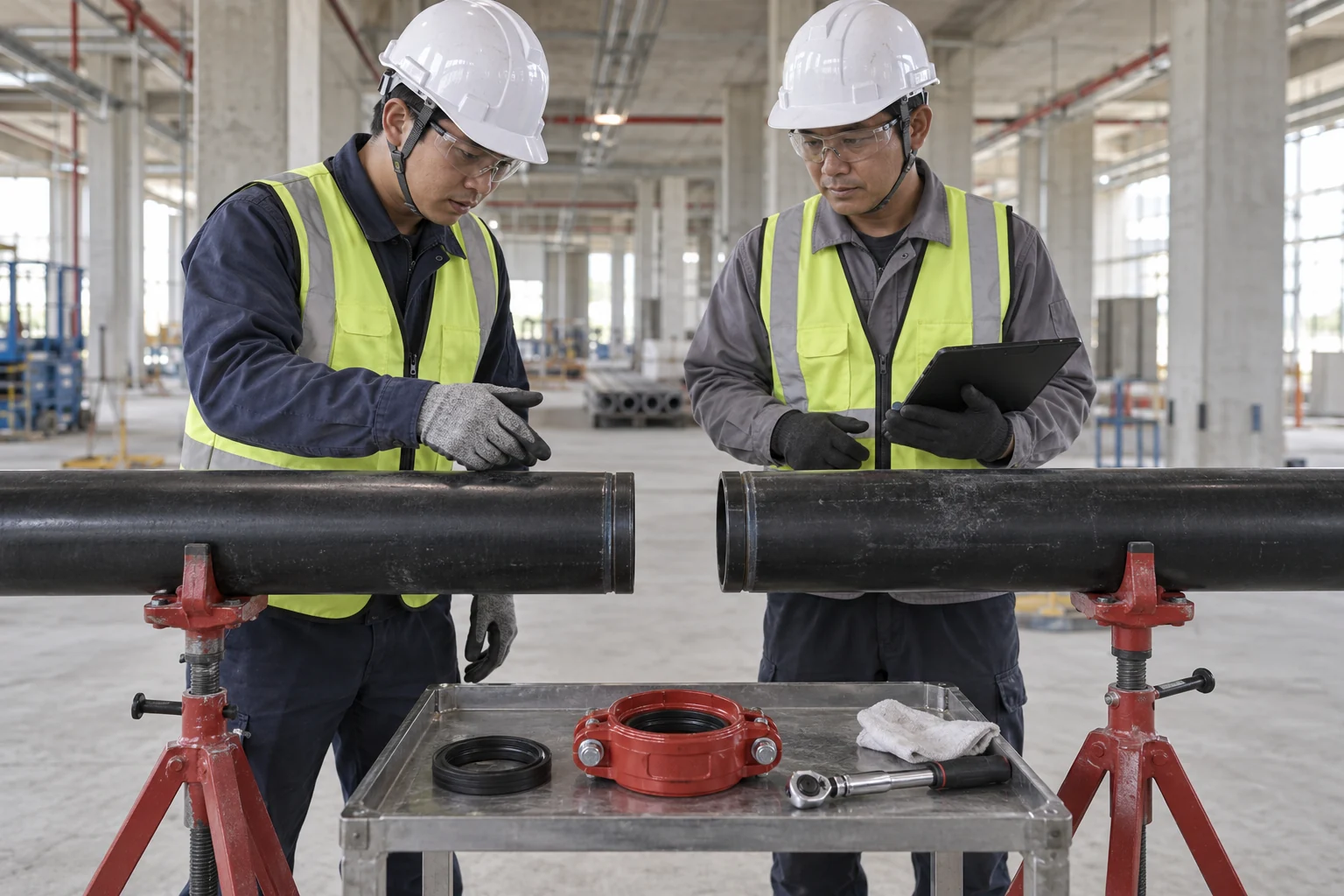 Retained source illustration: an AI-generated educational concept, not a real incident photograph or evidence of equipment suitability.
The following scenario, comparisons and example records are hypothetical teaching material. They do not reproduce actual incidents, measurements, signatures or approvals.
| Item | Hypothetical situation |
|---|---|
| Initial state | An installer tightens a sprinkler coupling using a torque value from a previous project. |
| Change | The housing remains asymmetric and part of the gasket is visibly displaced. |
| Failure path | The supervisor proposes allowing the pressure test to determine whether the joint is acceptable. |
| Possible harm | An incorrectly engaged or damaged joint can leak, release fluid or separate during filling and testing. |
| Barrier | Mark and hold the joint, verify depressurization, inspect the groove and parts, reassemble to the actual model instructions and release it only after documented assembly inspection. |
The coupling is not a substitute for pipe support during assembly. Keep each pipe stable and use suitable alignment tools with hands clear of closing gaps. Do not pull unacceptable alignment into place with coupling bolt force.
Initial assembly, lubrication and completion criteria vary by model and gasket. Obtain the actual instructions at the joint. A specified maximum permissible torque is not automatically a target torque, and reaching a wrench setting cannot replace required visual engagement checks.
A pressure test cannot replace assembly inspection. Separate the accepted joint list from held or incomplete joints before handover for testing. Any later leak returns the work to a separately controlled depressurized and drained state before adjustment.
System boundaries include trapped sections behind valves and branches. Confirm the actual new-work separation immediately before opening or adjusting a connection. Discovery of an operating fire-system connection changes the scope and requires the appropriate impairment and operations process.
| Decision | Reason and evidence |
|---|---|
| Known facts | The housing remains asymmetric and part of the gasket is visibly displaced. |
| Unresolved | The supervisor proposes allowing the pressure test to determine whether the joint is acceptable. |
| Hold reason | Stop for uncertain operating-system boundaries, trapped pressure or fluid, damaged grooves, incompatible gaskets, housing asymmetry, damaged bolts, moving supports or unmet model-specific assembly criteria. |
| Evidence needed | Tool and fastener condition; Specified tightening sequence; Housing and groove engagement; Model completion evidence. |
| Next decision | Mark and hold the joint, verify depressurization, inspect the groove and parts, reassemble to the actual model instructions and release it only after documented assembly inspection. |
5. Conditional decisions and common errors
| Condition | Action | Evidence | Proceed when |
|---|---|---|---|
| Pressure boundary uncertain | Do not open or adjust the joint. | Section valves branches and drainage. | Safe isolated section verified. |
| Gasket or housing abnormal | Mark and hold the joint. | Parts groove and model criteria. | Corrected assembly inspected. |
| Pipe misaligned | Restore support and alignment. | Permitted geometry and tool method. | Pipe stable within allowed limits. |
| Testing requested | Transfer assembly evidence and holds. | Joint register and separate test plan. | Testing authority accepts its scope. |
| Comparison | Situation A | Situation B |
|---|---|---|
| Wrench reaches setting | The applicable model criteria and visual joint condition are satisfied. | The number came from another coupling. |
| No leakage observed | Assembly inspection is complete and separately recorded. | Uninspected parts are accepted solely because they have not leaked. |
6. Roles and responsibilities
| Role | Responsibility |
|---|---|
| Work supervisor | Confirm scope, task sequence, exclusion and stop authority. Coordinate confirm section and product with affected operations. |
| Technical reviewer | Resolve the actual design and equipment limits: Section and boundary ID; Pressure and drainage evidence; Pipe groove and model data; Design and product basis. |
| Work crew | Perform inspect ends and gasket using the approved procedure; report any mismatch before proceeding. |
| Inspector / assessor | Verify Joint ID and inspector; Gasket and housing condition; Required completion checks; Accepted or held status. Record what was actually checked and what remains unresolved. |
| Release / receiving authority | Confirm Accepted and held joint list; Inspection and repair records; Test boundary and responsible lead; Clear area and remaining limits. Transfer restrictions and the next permitted stage. |
These are responsibility examples, not invented statutory credentials. Meet the actual training, competent-person, qualified-person and licensing requirements for the assigned work. Anyone may raise a hazard and request a stop; only the designated authority may release the affected stage after evidence is reviewed.
7. Hold points and record comparison
| Hold point | Evidence before release | Confirmation / approval |
|---|---|---|
| HP-0 Start | Scope, jurisdiction, equipment identity, responsible people and emergency arrangements. | |
| HP-1 Inspect ends and gasket | Outside diameter and groove; End condition and cleanliness; Gasket grade and damage; Lubricant and application basis | |
| HP-2 Tighten coupling | Tool and fastener condition; Specified tightening sequence; Housing and groove engagement; Model completion evidence | |
| HP-3 Hold and reassemble | Cause and affected joints; Pressure and support recheck; Replacement and reassembly; Repeat inspection evidence | |
| HP-4 Hand over for testing | Accepted and held joint list; Inspection and repair records; Test boundary and responsible lead; Clear area and remaining limits |
Hold points are internal evidence gates. They do not replace statutory permits or actual signatures. Recheck affected gates after a change, abnormal event or shift transfer. The blank record must identify the evidence, person, time, limits and release scope.
| Record | Insufficient record | Record checklist |
|---|---|---|
| Boundary | Section checked | □ Section and boundary ID□ Pressure and drainage evidence□ Pipe groove and model data□ Design and product basis |
| Materials | New gasket | □ Outside diameter and groove□ End condition and cleanliness□ Gasket grade and damage□ Lubricant and application basis |
| Assembly | Torque reached | □ Tool and fastener condition□ Specified tightening sequence□ Housing and groove engagement□ Model completion evidence |
| Rework | Tightened again | □ Cause and affected joints□ Pressure and support recheck□ Replacement and reassembly□ Repeat inspection evidence |
The □ boxes are static prompts, not saved or interactive approvals. Each checks one record element. A tick alone does not establish suitability or permission to restart. Link equipment IDs and supporting records; retain unresolved matters and the earlier record when conditions change.
8. Site checklist and emergency response
| Check item | Result | Person / action |
|---|---|---|
| Section and boundary ID | ||
| Hangers stands and stability | ||
| Outside diameter and groove | ||
| Alignment and hand clearance | ||
| Tool and fastener condition | ||
| Joint ID and inspector | ||
| Cause and affected joints | ||
| Accepted and held joint list | ||
| Emergency arrangements and unresolved restrictions communicated |
Stop work: Stop for uncertain operating-system boundaries, trapped pressure or fluid, damaged grooves, incompatible gaskets, housing asymmetry, damaged bolts, moving supports or unmet model-specific assembly criteria.
Emergency response: For fluid release or pipe movement, withdraw and prevent access. Ask the designated system operator to stop, isolate and depressurize from a safe location. Do not block a leak by hand or adjust coupling bolts under pressure. Call 911 for serious injury and preserve required emergency access; any operating fire-system impairment requires its separate response process.
9. Sources and review limits
Official-source review date: October 14, 2026. The following review is limited to the public provisions or selected manufacturer material identified below. It does not establish that any authority approved this article or the actual installation.
- OSHA 1926.451: Applicable scaffold access and protection when scaffolding is selected; does not approve pipe supports.
- OSHA 1926.501: Applicable construction fall-protection scope; assess the actual access system.
- Victaulic I-009N instructions: Selected Rev O pressure, component, lubrication, assembly and visual-inspection guidance for Style 009N. Model-specific criteria are examples, not instructions for every coupling.
- Victaulic Style 009N product page: Product and document links; actual listing, application and current instruction revision still require review.
- OSHA State Plans: jurisdiction and coverage overview; identify the actual state program before use.
Paid consensus standards and site-specific calculations, manuals, inspection records and product certificates were not independently obtained or verified unless specifically identified. Korean legal citations remain in the preserved Korean source as source history; they are not represented as US legal duties.
10. PDF guidance and FAQ
PDF A covers basic task controls; B examines technical failures; C focuses on supervision, evidence and handover. Each has six rows and three items per main cell. They are complementary extracts: apply all eight body stages and the applicable site procedure. An omitted stage is not permission to omit its controls. PDF HP-0 through HP-4 are worksheet labels; match the event, evidence and authority rather than assuming they match another permit by number.
P/S/R/A, actual measurements, confirmations and signatures remain blank. The PDFs are uncompleted reference worksheets, not issued work permits.
Content group ID: jsa-sprinkler-grooved-coupling-assembly
Do all couplings use the same torque?
No. Apply the exact model, size and fastener instructions, including all visual completion criteria.
Does every new gasket need added lubricant?
No. Follow the actual gasket and service-specific instructions; avoid incompatible or excessive lubricant.
Should every coupling be disassembled first?
No. Some products are designed for initial assembly without disassembly. Use the model procedure.
Can a suspect joint be checked by pressurizing it?
Complete and document the required assembly inspection first. Pressure testing is a separate authorized activity and cannot cure an assembly defect.
Has a professional verified or approved this document?
No. This is AI-assisted reference material. Editorial and layout checks are not a physical inspection or professional technical approval. Obtain qualified professional review and required site approval before use.
11. Revision history and authorship
Reference content written and revised with AI. It has not been verified or approved by a professional. Review by a suitably qualified professional and site approval are required before use.
This system has not physically inspected the equipment, structures, ground, atmosphere or worksite. The document does not replace legal advice, manufacturer procedures, engineering design, inspection certificates, qualification evidence, the site risk assessment or an actual work permit.
Before use, a suitably qualified and authorized person must review the actual equipment, loads, methods, protection, inspection and emergency arrangements and resolve open issues. Record the real reviewer, organization, qualifications, delegated authority, reviewed documents, date, signature, exclusions and conditions of approval separately.
| Date | Version | Change | Review status |
|---|---|---|---|
| 2026-10-08 | 1.0 | Korean source revision retained in the source snapshot. | Historical editorial status; not US professional approval. |
| 2026-10-14 | US 1.0 | US localization of the assigned Korean source; task reasoning, educational image and history retained; US scope and sources reviewed. | AI-assisted editorial work; professional approval not performed. |