Preattached sign panels change wind area, center of gravity and the location of wind force, not only weight. The lift plan must match the actual assembly and temporary state. A changed radius also changes the crane capacity condition.
This is reference content written and revised with AI. It has not been verified or approved by a professional. Review by a suitably qualified professional and site authorization are required before use.
Stop before starting
Hold lifting, support release or reopening for public intrusion, signal loss, gusts beyond the plan, increased radius without review, anchor damage, incomplete temporary connections or unverified traffic clearance.
1. Legal and technical scope
| Basis | Scope and limits |
|---|---|
| OSHA 1926.1402 | Ground support for covered cranes. |
| OSHA 1926.1417 | Covered-crane operating procedures and actual load conditions. |
| FHWA MUTCD | Current publication and state implementation context; project traffic plan still required. |
Resolve applicable construction crane and steel-erection requirements, including 1926.1402, 1926.1417 and the actual Subpart R scope. The highway authority controls closure and reopening under its approved traffic plan and applicable MUTCD/state requirements. FHWA lists the 11th Edition with Revision 1 as its current publication; confirm the jurisdiction and adopted requirements. This article sets no universal wind, temporary-bolt or clearance value.
2. Scope and required inputs
Included work
Ground assembly, lifting, setting, permanent fastening and inspection of a steel overhead road-sign gantry on accepted foundations, followed by a separate traffic-opening handover.
Separate assessment
Existing-structure removal, electrical wiring and foundation construction are separate tasks. Changes to sign preattachment, panel area or night closure require a reviewed plan.
| Required input | Evidence to obtain |
|---|---|
| Review design and lift | Foundation and anchors; Weight center and panels; Lift configuration; Traffic and utility plan |
| Set crane and access | Ground and supports; Exclusion zone; Fall and rescue plan; Traffic-control positions |
| Assemble on ground | Stable supports; Connection detail; Rigging and lift points; Preattached-panel check |
| Trial lift and raise | Balance and sling seating; Weather observation; Exclusion maintained; Actual load configuration |
No actual equipment model, SDS, site measurements, design calculations or authorization record was supplied. Product-specific limits and methods must be verified before use. Federal OSHA is a baseline within its scope; determine the applicable State Plan and local requirements. Manufacturer guidance is not government approval; an incorporated standard differs from voluntary guidance. No nationwide-compliance or expert-approval claim is made.
3. Eight-stage JSA
| Job stage | Hazards and effects | Failure factors | Technical and procedural controls | Site verification | P | S | R | A |
|---|---|---|---|---|---|---|---|---|
| 1. Review design and lift | 1. Foundation failure2. Assembly drop3. Traffic strike4. Power-line contact | 1. Anchor evidence absent2. Actual weight unknown3. Closure scope missing4. Overhead conflict missed | 1. Accept foundation records2. Match actual assembly3. Approve traffic closure4. Review overhead exposures | 1. Foundation and anchors2. Weight center and panels3. Lift configuration4. Traffic and utility plan | ||||
| 2. Set crane and access | 1. Crane settlement2. Public intrusion3. Elevated fall4. Traffic-control injury | 1. Support unreviewed2. Boundary incomplete3. Access absent4. Flagger exposed | 1. Review reactions and ground2. Separate traffic and plant3. Provide accepted access4. Protect closure crew | 1. Ground and supports2. Exclusion zone3. Fall and rescue plan4. Traffic-control positions | ||||
| 3. Assemble on ground | 1. Member roll2. Joint pinch3. Rigging failure4. Panel release | 1. Supports absent2. Hands align holes3. Lift points damaged4. Panels uninspected | 1. Restrain long members2. Use alignment tools3. Inspect lift attachments4. Verify panel fastening | 1. Stable supports2. Connection detail3. Rigging and lift points4. Preattached-panel check | ||||
| 4. Trial lift and raise | 1. Rotation2. Wind swing3. Load strike4. Crane overload | 1. Balance unchecked2. Wind area ignored3. People below4. Radius increases | 1. Check balance low2. Apply actual weather limits3. Clear load path4. Monitor radius and capacity | 1. Balance and sling seating2. Weather observation3. Exclusion maintained4. Actual load configuration | ||||
| 5. Set temporary joints | 1. Hand crush2. Anchor damage3. Dropped tools4. Collapse after release | 1. Hands in joint2. Braces incomplete3. Tools unsecured4. Support released early | 1. Guide with suitable tools2. Install planned restraints3. Control loose parts4. Retain hoist until accepted | 1. Hand and body position2. Anchors bolts and braces3. Drop-zone control4. Support-release evidence | ||||
| 6. Fasten and survey | 1. Joint slip2. Panel loss3. Reaction crush4. Access fall | 1. Method mixed2. Inspection skipped3. Reaction point wrong4. Overreach | 1. Use approved fastening2. Inspect each connection3. Control tool reaction4. Maintain safe access | 1. Fastening method2. Plumb height and direction3. Panel and brace checks4. Access and reaction path | ||||
| 7. Hold abnormal condition | 1. Residual-load motion2. Wind overturn3. Weakened connection4. Recovery collision | 1. Cause unreviewed2. Limits ignored3. Holes modified casually4. Signals conflict | 1. Exclude unstable zone2. Use safe-load recovery plan3. Review design alterations4. Keep one signal authority | 1. Support and residual load2. Changed weather radius3. Alteration review4. Restart conditions | ||||
| 8. Inspect and open road | 1. Loose-item fall2. Vehicle collision3. Connection failure4. Closure-removal strike | 1. Tools left2. Clearance unmeasured3. Defects not transferred4. Removal sequence wrong | 1. Account for loose items2. Measure traffic clearance3. Resolve acceptance holds4. Release traffic separately | 1. Final connection records2. Clearance survey3. Sign and debris checks4. Highway authority release |
P = likelihood; S = severity; R = risk under the site method; A = site-defined acceptance/authorization. These actual assessment cells are blank. A low score never overrides a missing safeguard or a legal or manufacturer restriction.
4. Fictional scenario and failure mechanisms
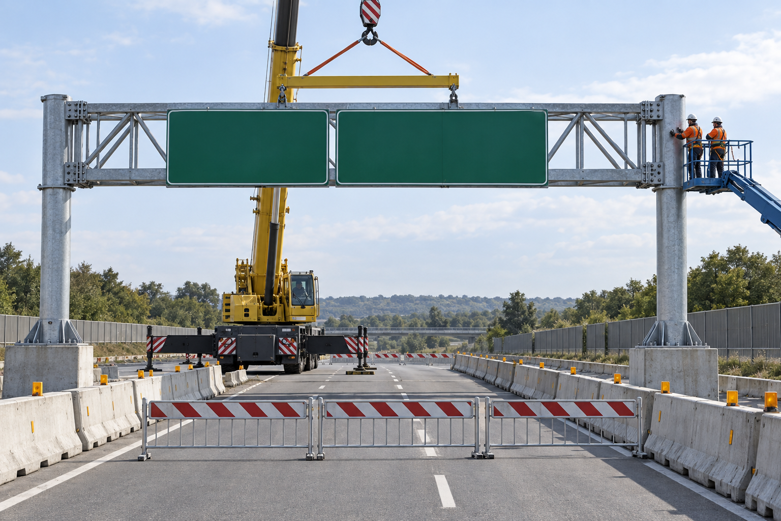
This illustration provides educational context. It is not an actual incident photograph or evidence of equipment suitability; any AI-generated depiction is illustrative only.
The scenario and record comparisons are fictional teaching examples, not records of real incidents, measurements, inspections, signatures or approvals.
| Stage | Fictional situation |
|---|---|
| Initial situation | A fictional gantry is lifted with sign panels already attached. |
| Changed condition | A gust occurs and the radius increases during alignment. |
| Failure path | Partial bolting is mistaken for a complete structure and both rigging and road closure are about to be released. |
| Possible outcome | The assembly could rotate, overturn or drop parts into traffic. |
| Prevention barrier | Hold release, reassess wind and actual crane configuration, verify staged stability and final connections, then separately obtain traffic-opening authorization. |
Failure mechanisms
Preattached sign panels change wind area, center of gravity and the location of wind force, not only weight. The lift plan must match the actual assembly and temporary state. A changed radius also changes the crane capacity condition.
An accepted foundation cannot compensate for incomplete column-to-beam connections. Identify the staged load path through anchors, braces and temporary connections and the conditions for releasing the lifting support.
Crane departure does not open the road. Final connection and panel checks, measured traffic clearance, sign orientation, loose-item removal and safe removal of traffic controls require their own accepted handover.
Work sequence: Review design and lift → Set crane and access → Assemble on ground → Trial lift and raise → Set temporary joints → Fasten and survey → Hold abnormal condition → Inspect and open road. This is a teaching flow, not a device drawing or a complete operating procedure.
5. Conditional decisions and common errors
| Situation | Required action | Evidence | Proceed when |
|---|---|---|---|
| Panel arrangement changes | Review actual lift | Weight, center and wind area | Configuration accepted |
| Wind or radius changes | Hold movement safely | Actual chart and support conditions | Lift released |
| Temporary connection only | Retain lifting support | Staged bolts, anchors and braces | Stability accepted |
| Road reopening proposed | Inspect complete clearance | Survey, debris and traffic plan | Authority releases |
Similar observations, different decisions
The scenario and record comparisons are fictional teaching examples, not records of real incidents, measurements, inspections, signatures or approvals.
| Observation | Insufficient conclusion | Required distinction |
|---|---|---|
| Foundation accepted | Foundation condition | Temporary joints separate |
| Gantry set in position | Geometry achieved | Rigging release unproved |
| Crane leaves | Lifting completed | Road opening separate |
6. Roles and responsibilities
| Role | Responsibility |
|---|---|
| Work supervisor | Confirm foundation and anchors and the task scope, resources, interfaces and stop authority. |
| Qualified technical reviewer | Review ground and supports, model limits, compatibility and unresolved technical conditions within assigned competence. |
| Work crew | Apply the listed controls, report changes and stop when evidence or safeguards are missing. |
| Inspector / assessor | Record actual hand and body position and other relevant checks; do not mark unverified conditions as accepted. |
| Handover authority | Reconcile final connection records, restrictions and outstanding actions before the next task. Role labels do not establish a legal credential. |
Supervision and handover focus
| Stage | Management action | Evidence |
|---|---|---|
| Review design and lift | 1. Record foundation and anchors2. Record weight center and panels3. Record lift configuration | 1. Foundation and anchors2. Weight center and panels3. Lift configuration |
| Set crane and access | 1. Record ground and supports2. Record exclusion zone3. Record fall and rescue plan | 1. Ground and supports2. Exclusion zone3. Fall and rescue plan |
| Trial lift and raise | 1. Record balance and sling seating2. Record weather observation3. Record exclusion maintained | 1. Balance and sling seating2. Weather observation3. Exclusion maintained |
| Set temporary joints | 1. Record hand and body position2. Record anchors bolts and braces3. Record drop-zone control | 1. Hand and body position2. Anchors bolts and braces3. Drop-zone control |
| Hold abnormal condition | 1. Record support and residual load2. Record changed weather radius3. Record alteration review | 1. Support and residual load2. Changed weather radius3. Alteration review |
| Inspect and open road | 1. Record final connection records2. Record clearance survey3. Record sign and debris checks | 1. Final connection records2. Clearance survey3. Sign and debris checks |
7. Hold points and record comparison
| Hold point | Evidence before release | Actual approval |
|---|---|---|
| HP-0 Scope | Ground assembly, lifting, setting, permanent fastening and inspection of a steel overhead road-sign gantry on accepted foundations, followed by a separate traffic-opening handover. | |
| HP-1 Set crane and access | Ground and supports; Exclusion zone; Fall and rescue plan; Traffic-control positions | |
| HP-2 Trial lift and raise | Balance and sling seating; Weather observation; Exclusion maintained; Actual load configuration | |
| HP-3 Hold abnormal condition | Support and residual load; Changed weather radius; Alteration review; Restart conditions | |
| HP-4 Inspect and open road | Final connection records; Clearance survey; Sign and debris checks; Highway authority release |
Hold points are internal project checks. They are not universal statutory permits and do not grant work permission. Reassess after defects, changed conditions and shift changes.
Record comparison
The scenario and record comparisons are fictional teaching examples, not records of real incidents, measurements, inspections, signatures or approvals.
The boxes are static record prompts, not interactive or saved approvals. A tick does not establish suitability or permission to restart. Record the evidence, person, time and unresolved issues; retain the change history.
| Record | Insufficient record | Record checklist |
|---|---|---|
| Review design and lift | Only marked “OK” | □ Foundation and anchors□ Weight center and panels□ Lift configuration□ Traffic and utility plan |
| Trial lift and raise | Only marked “OK” | □ Balance and sling seating□ Weather observation□ Exclusion maintained□ Actual load configuration |
| Hold abnormal condition | Only marked “OK” | □ Support and residual load□ Changed weather radius□ Alteration review□ Restart conditions |
| Inspect and open road | Only marked “OK” | □ Final connection records□ Clearance survey□ Sign and debris checks□ Highway authority release |
8. Site checklist and emergency response
| Site check | Actual result | Person / action |
|---|---|---|
| Review design and lift: Foundation and anchors; Weight center and panels; Lift configuration; Traffic and utility plan | ||
| Set crane and access: Ground and supports; Exclusion zone; Fall and rescue plan; Traffic-control positions | ||
| Assemble on ground: Stable supports; Connection detail; Rigging and lift points; Preattached-panel check | ||
| Trial lift and raise: Balance and sling seating; Weather observation; Exclusion maintained; Actual load configuration | ||
| Set temporary joints: Hand and body position; Anchors bolts and braces; Drop-zone control; Support-release evidence | ||
| Fasten and survey: Fastening method; Plumb height and direction; Panel and brace checks; Access and reaction path | ||
| Hold abnormal condition: Support and residual load; Changed weather radius; Alteration review; Restart conditions | ||
| Inspect and open road: Final connection records; Clearance survey; Sign and debris checks; Highway authority release |
Stop work
Hold lifting, support release or reopening for public intrusion, signal loss, gusts beyond the plan, increased radius without review, anchor damage, incomplete temporary connections or unverified traffic clearance.
Emergency response
Maintain the road closure and load exclusion, stop movements safely under one signal authority and activate the site emergency plan. Keep people out of the gantry collapse zone until qualified stabilization and recovery arrangements are established.
9. Sources and review limits
Public-source access/review: 2026-10-14.
| Official source | Reviewed scope and limits |
|---|---|
| OSHA 1926.1402 | Ground support for covered cranes. |
| OSHA 1926.1417 | Covered-crane operating procedures and actual load conditions. |
| FHWA MUTCD | Current publication and state implementation context; project traffic plan still required. |
No actual equipment model, SDS, site measurements, design calculations or authorization record was supplied. Product-specific limits and methods must be verified before use. Federal OSHA is a baseline within its scope; determine the applicable State Plan and local requirements. Manufacturer guidance is not government approval; an incorporated standard differs from voluntary guidance. No nationwide-compliance or expert-approval claim is made.
10. PDF guidance and FAQ
PDF A covers basic task controls; B focuses on technical failures; C covers supervision, records and handover. The article has eight stages with four items per main cell; each PDF has six key stages with three items per main cell. P/S/R/A, measurements, confirmations and signatures remain blank for actual site assessment.
PDFs are complementary six-stage extracts. Apply all eight body stages and the actual equipment/site procedure.
Can signs be attached before lifting?
Only when the actual panel arrangement, weight, center and wind effects are covered by the accepted lift and stability plan.
Can a few temporary bolts support the gantry?
Use the designed staged connection and release criteria; this document supplies no generic bolt count.
Does crane removal authorize traffic?
No. Resolve final inspection, clearance and the highway authority's reopening requirements.
Has a professional verified or approved this document?
No. Public sources and editorial, layout and consistency checks were reviewed using AI. No site inspection or professional technical approval has been performed. Obtain appropriate professional review before use.
11. Revision history and authorship
This is reference content written and revised with AI. It has not been verified or approved by a professional. Review by a suitably qualified professional and site authorization are required before use.
| Date | Version | Change | Review status |
|---|---|---|---|
| 2026-10-14 | US 1.0 | New US edition from assigned Korean source; task decisions, records and PDFs localized. | AI editorial review; no professional technical approval |
Korean edition revision history: 2026-09-19 (v1.1): earlier published draft/version retained in the source history; 2026-09-26 (v1.2): task decisions, record checklist, JSA and three PDF variants revised. These are editorial records, not professional technical approval. US v1.0 adapts the earlier edition to United States requirements and terminology.
Site reviewers must add their actual qualifications, scope, date and approval only after the review occurs.