For a US site, first distinguish a fabricated truss, an open-web steel joist and a systems-engineered metal building. The critical handoff is between crane support and the structure’s own stable load path. Agree the first stable bay, every intermediate release condition and protected access before lifting. Roof cladding is a later loading stage with its own wind, fixing and fragility checks.
Release each member only after its designed stable stage is verified
This is reference content written and revised with AI. It has not been verified or approved by a professional. Review by a suitably qualified professional and site authorisation are required before use.
Stop work
Stop for missing design information, unstable supports, unverified connection or bracing, changed ground, uncontrolled people below, loss of signals, unsafe electrical clearance, absent fall protection, damaged lifting gear or weather outside the plan. Stop before an unrestrained panel or member becomes uncontrollable.
1. Legal and technical scope
| Basis | Application limits |
|---|---|
| OSHA 1926.754 — Structural steel assembly | Current official provisions and eTool scope reviewed: stability during erection and controlled decking loads. |
| OSHA 1926.756 — Beams and columns | Official text reviewed; scope of solid-web members and connection/release requirements. |
| OSHA 1926.757 — Open web steel joists | Official text reviewed; joist type, span and erection bridging provisions are specific. |
| OSHA 1926.758 — Systems-engineered metal buildings | Classification distinction checked against OSHA steel-erection enforcement guidance; not treated as a generic truss rule. |
| OSHA 1926.760 — Fall protection | Official text reviewed; different protected work categories and systems. |
| OSHA 1926.502 — Fall protection systems | Anchorage and horizontal lifeline provisions; actual system design remains a competent-person task. |
| HSE — Steel erection | Foreign guidance: erection sequence, temporary stability and designer coordination. |
| HSE — Fragile surfaces | Foreign guidance: avoid exposure and plan protected access. |
Federal OSHA construction requirements must be matched to the actual activity and member classification; check the applicable State Plan as well. Section 1926.756(a) addresses solid-web structural members and its specified two-bolt release rule or engineered equivalent, not every roof truss. Section 1926.757 addresses open-web steel joists and joist girders; systems-engineered metal buildings have separate provisions in 1926.758. None removes the obligation to maintain erection stability.
Section 1926.760 provides the steel-erection fall-protection framework, including specific connector and controlled-decking provisions. Do not turn it into a universal personal-harness-only rule or treat exemptions as permission for unsafe access. Under 1926.502, the 5,000 lb anchorage alternative is not a generic horizontal lifeline cable rating: the qualified-person design alternative and complete system must be assessed. HSE sources below are foreign technical guidance. Actual engineering drawings and manufacturer instructions were not reviewed.
2. Scope and required inputs
Included scope
Identify the actual steel roof system; plan erection, ground support, lifting, connections, temporary and permanent bracing, protected access, insulated panel installation and controlled handover.
Separate review
This outline does not design the truss, crane lift, anchors or temporary works. Tandem lifts, live electrical work, demolition, welding and asbestos disturbance require their own competent assessment and procedures.
| Required input | What to verify |
|---|---|
| Erection plan | Member and drawing IDs · Bracing sequence · Release criteria · Load limits |
| Ground and access | Ground assessment · Access protection · Utility isolation plan · Rescue arrangements |
| Rig and lift | Lift plan and member ID · Rigging inspection · Wind and radius limits · Exclusion zone |
| Brace and release | Stage stability check · Brace and anchor check · Connection status · Release decision |
| Roof panels | Panel fixing schedule · Opening protection · Weather stop criteria · Roof load map |
| Handover | Joint inspection record · Brace removal authority · Opening and access map · Signed handover blank |
Obtain issued erection drawings and the actual crane, access equipment, rigging, fall system and panel instructions. No paid standard or equipment-specific manual was reviewed. Bolt count, grade, tightening, bracing force, anchor capacity, wind limits and roof bundle loads must come from the applicable design and equipment configuration; an example number is not approval.
Select head, eye, foot, hand and hearing protection for the actual exposure. Where personal fall protection is needed, verify the complete compatible system, rated supporting structure, number of users, edge suitability, fall clearance and rescue. A purlin, temporary guy or crane hook is not an assumed fall anchor.
3. Eight-stage JSA
| Job stage | Hazards and effects | Failure factors | Technical and procedural controls | Site verification | P | S | R | A |
|---|---|---|---|---|---|---|---|---|
| 1. Erection plan | 1. Unstable first bay2. Wrong member type3. Premature roof load4. Unplanned change | 1. No staged design2. Joist rule misapplied3. Load path incomplete4. Old drawing used | 1. Identify member class2. Design each stable stage3. Set release conditions4. Approve design changes | 1. Member and drawing IDs2. Bracing sequence3. Release criteria4. Load limits | ||||
| 2. Ground and access | 1. Crane settlement2. Falls during setup3. Live power lines4. Blocked rescue | 1. Unknown buried voids2. Protection fitted late3. Unsafe crane clearance4. No recovery route | 1. Verify bearing and mats2. Protect access first3. Agree electrical controls4. Provide rescue access | 1. Ground assessment2. Access protection3. Utility isolation plan4. Rescue arrangements | ||||
| 3. Rig and lift | 1. Dropped truss2. Sling damage3. Swinging load4. Load entanglement | 1. Wrong lifting points2. Unrated sling angle3. Gusts change radius4. Conflicting signals | 1. Use approved lift points2. Check WLL and geometry3. Set load-specific limits4. Use one signal lead | 1. Lift plan and member ID2. Rigging inspection3. Wind and radius limits4. Exclusion zone | ||||
| 4. Land and connect | 1. Truss rolls2. Crushed hands3. Joint failure4. Support moves | 1. Missing design bolts2. Drift pin bears load3. Wrong bolt grade4. Column not stable | 1. Maintain planned support2. Fit specified connections3. Keep hands clear4. Check column stability | 1. Drawing bolt schedule2. Connection inspection3. Support condition4. Access platform | ||||
| 5. Brace and release | 1. Lateral buckling2. Guy anchor failure3. Crane side loading4. Progressive collapse | 1. Brace path unfinished2. Unverified anchor3. Forced alignment4. Release not authorized | 1. Complete stage bracing2. Verify anchors and ties3. Avoid forced crane pulls4. Authorise each release | 1. Stage stability check2. Brace and anchor check3. Connection status4. Release decision | ||||
| 6. Advance frame | 1. Unsupported next bay2. Falls at open frame3. Early brace removal4. Local overload | 1. Sequence bypassed2. Walking bare steel3. Purlin used as anchor4. Bundles placed early | 1. Follow stable bay sequence2. Use protected work access3. Retain required braces4. Approve roof load zones | 1. Next bay readiness2. Fall system design3. Brace retention plan4. Permitted loads | ||||
| 7. Roof panels | 1. Wind lifts panel2. Fall through rooflight3. Panel tips at edge4. Bundle slides | 1. Incomplete fixing2. Fragility unassessed3. Standing on overhang4. Load not restrained | 1. Fix to model and plan2. Guard rooflights and gaps3. Use supported walkways4. Secure approved bundles | 1. Panel fixing schedule2. Opening protection3. Weather stop criteria4. Roof load map | ||||
| 8. Handover | 1. Residual instability2. Loose sharp offcuts3. Hidden roof openings4. Unauthorized access | 1. Braces removed early2. Waste thrown down3. Inspection assumed4. Limits not transferred | 1. Release braces by design2. Lower contained waste3. Inspect joints and roof4. Transfer access limits | 1. Joint inspection record2. Brace removal authority3. Opening and access map4. Signed handover blank |
PDF A covers basic task controls; B focuses on technical failures; C covers supervision, records and handover. The article has eight stages with four items per main cell; each PDF has six key stages with three items per main cell. P/S/R/A, measurements, confirmations and signatures remain blank for actual site assessment.
4. Fictional scenario and failure mechanisms
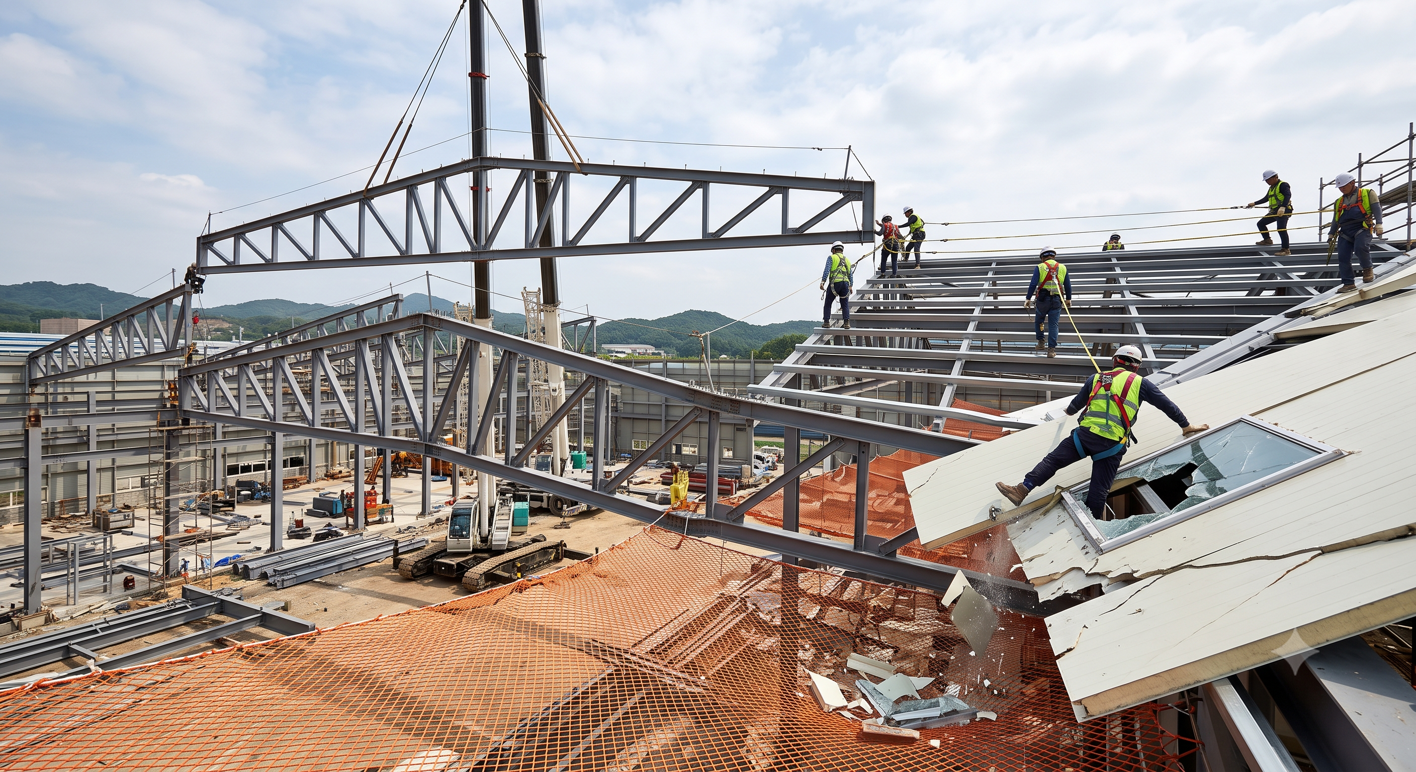
Retained educational illustration; not evidence of an actual incident.
The scenario and record comparisons are fictional teaching examples, not records of real incidents, measurements, inspections, signatures or approvals.
| Item | Fictional scenario |
|---|---|
| Initial situation | A hypothetical US crew lands a fabricated roof truss but uses a joist checklist without verifying the member classification. |
| Changed condition | Two bolts appear fitted, but the crew has not checked the specified connection or temporary guy anchor. |
| Failure path | As crane support is reduced, the assembly can move outside its intended plane because the required load path is incomplete. |
| Possible outcome | Movement could overload adjoining members or expose workers to a fall; no measured load, real accident or injury outcome is asserted. |
| Prevention barrier | Hold the release, keep people outside the collapse zone and have the erection designer resolve the missing stability condition. |
Failure mechanisms
A truss designed for the finished roof may need different restraint during lifting and erection. A brace must transfer force through its connections and anchors to a verified support; the presence of a cable alone proves nothing.
Euler’s ideal column relationship explains why effective unrestrained length matters, but it does not calculate a real truss’s lateral stability or predict a universal percentage loss of capacity. Check geometry, imperfections, load position, connection stiffness and the actual construction stage.
Installing two bolts does not automatically create a moment connection. The release condition must fit the member classification, joint detail and temporary stability plan. Maintain the planned crane support without using side pull or uncontrolled preload to force alignment.
Panel wind action depends on area, orientation, gusts and exposure, while early roof loads can be concentrated on one purlin. Establish the most restrictive applicable limits, secure the assembly before those limits are reached and prevent access to unverified panels or rooflights.
Decision sequence
| Decision stage | What to verify |
|---|---|
| Known facts | Identify the member type, current drawings and erection designer. |
| Unresolved matters | Trace support from the suspended member through connections, braces and anchors. |
| Reason to hold | Stop if the next stable stage or the fall-protected access is not established. |
| Required evidence | Record actual connection, brace, ground and weather evidence against the plan; leave this reference form blank. |
| Restart decision | The authorized site team decides release for that stage and reassesses after any change. |
5. Conditional decisions and common errors
| Condition | Action | Evidence | Proceed when |
|---|---|---|---|
| Bolts visible | Check the specified connection | Drawing and inspection | Specified connection complete |
| Bracing missing | Hold crane release safely | Stage stability assessment | Designed stage established |
| Wind changes | Stop and secure to the plan | Load-specific weather criteria | Safe restart authorized |
| Roof looks complete | Check fixing, loads and gaps | Roof and access inspection | Handover conditions met |
Similar situations, different decisions
The scenario and record comparisons are fictional teaching examples, not records of real incidents, measurements, inspections, signatures or approvals.
| Comparison | Situation A | Situation B |
|---|---|---|
| Crane support | Temporary planned assistance | Not permanent bracing or fall anchorage |
| Roof net | Mitigates a person’s fall where suitable | Does not arrest a collapsing steel frame |
| Panel fixing | Transfers panel loads to supports | Lap stitching alone is not every required fixing |
6. Roles and responsibilities
| Role | Responsibility |
|---|---|
| Work supervisor | The site manager coordinates exclusion zones, work interfaces, access restrictions and the stage handover. |
| Technical reviewer | The competent erection designer defines stability, first-bay restraints, connection requirements, loading limits and authorized changes. Resolve the applicable OSHA member category; do not apply the solid-web two-bolt rule to every fabricated truss. |
| Work crew | The lifting team checks ground, crane configuration, rigging, signals and load control, and stops on deviation. |
| Inspector / assessor | Installers follow the approved sequence from protected access, check actual connection and bracing status and report defects without improvisation. |
| Release / handover authority | The receiving team verifies the inspection evidence, retained protection and unresolved restrictions; actual signatures and approval remain blank. |
Supervision, records, handover
| Job stage | Technical and procedural controls | Site verification |
|---|---|---|
| Erection plan | 1. Allocate erection designer2. Freeze drawing revision3. Define first stable bay | 1. Design responsibility2. Issued drawing set3. First-bay release plan |
| Ground and access | 1. Coordinate shared access2. Accept ground evidence3. Arrange rescue resources | 1. Ground report reference2. Access ownership3. Rescue team and route |
| Land and connect | 1. Hold incomplete connections2. Resolve bolt deviations3. Record support condition | 1. Connection checklist2. Approved deviation record3. Support inspection |
| Brace and release | 1. Control crane release2. Approve brace changes3. Track temporary restraints | 1. Release authority2. Brace change approval3. Restraint register |
| Roof panels | 1. Authorise roof loading2. Coordinate weather stops3. Accept fixing method | 1. Approved load zones2. Weather decision record3. Panel method reference |
| Handover | 1. Close unresolved defects2. Approve brace removal3. Transfer roof restrictions | 1. Defect closeout evidence2. Removal authorisation3. Handover record |
7. Hold points and record comparison
| Hold point | Evidence before release | Confirmation / approval |
|---|---|---|
| Start | Identify the actual steel roof system; plan erection, ground support, lifting, connections, temporary and permanent bracing, protected access, insulated panel installation and controlled handover. | |
| HP-1 Ground and access | Ground assessment · Access protection · Utility isolation plan · Rescue arrangements | |
| HP-2 Land and connect | Drawing bolt schedule · Connection inspection · Support condition · Access platform | |
| HP-3 Brace and release | Stage stability check · Brace and anchor check · Connection status · Release decision | |
| HP-4 Handover | Joint inspection record · Brace removal authority · Opening and access map · Signed handover blank |
Complete after actual checks. Recheck after changes, defects or shift handover.
Record comparison examples
The scenario and record comparisons are fictional teaching examples, not records of real incidents, measurements, inspections, signatures or approvals.
The boxes are static record prompts, not interactive or saved approvals. A tick does not establish suitability or permission to restart. Record the evidence, person, time and unresolved issues; retain the change history.
| Record type | Insufficient record | Record checklist |
|---|---|---|
| Design | Only OK | □ Member and drawing IDs□ Bracing sequence□ Release criteria□ Load limits |
| Joint | Only OK | □ Drawing bolt schedule□ Connection inspection□ Support condition□ Access platform |
| Bracing | Only OK | □ Stage stability check□ Brace and anchor check□ Connection status□ Release decision |
| Handover | Only OK | □ Joint inspection record□ Brace removal authority□ Opening and access map□ Signed handover blank |
8. Site checklist and emergency response
| Check item | Result | Person / action |
|---|---|---|
| □ Erection plan: Member and drawing IDs | ||
| □ Ground and access: Ground assessment | ||
| □ Rig and lift: Lift plan and member ID | ||
| □ Land and connect: Drawing bolt schedule | ||
| □ Brace and release: Stage stability check | ||
| □ Advance frame: Next bay readiness | ||
| □ Roof panels: Panel fixing schedule | ||
| □ Handover: Joint inspection record | ||
| □ Release / handover authority |
Stop work
Stop for missing design information, unstable supports, unverified connection or bracing, changed ground, uncontrolled people below, loss of signals, unsafe electrical clearance, absent fall protection, damaged lifting gear or weather outside the plan. Stop before an unrestrained panel or member becomes uncontrollable.
Emergency response
Stop movement from a safe position and clear the potential collapse and drop zone. Call the site emergency team. Do not enter unstable steelwork or climb to an unplanned rescue. Use the prepared rescue method with a stable verified access system; isolation and structural re-entry require competent reassessment.
9. Sources and review limits
2026-10-11
| Source | Scope and limitations |
|---|---|
| OSHA 1926.754 — Structural steel assembly | Current official provisions and eTool scope reviewed: stability during erection and controlled decking loads. |
| OSHA 1926.756 — Beams and columns | Official text reviewed; scope of solid-web members and connection/release requirements. |
| OSHA 1926.757 — Open web steel joists | Official text reviewed; joist type, span and erection bridging provisions are specific. |
| OSHA 1926.758 — Systems-engineered metal buildings | Classification distinction checked against OSHA steel-erection enforcement guidance; not treated as a generic truss rule. |
| OSHA 1926.760 — Fall protection | Official text reviewed; different protected work categories and systems. |
| OSHA 1926.502 — Fall protection systems | Anchorage and horizontal lifeline provisions; actual system design remains a competent-person task. |
| HSE — Steel erection | Foreign guidance: erection sequence, temporary stability and designer coordination. |
| HSE — Fragile surfaces | Foreign guidance: avoid exposure and plan protected access. |
This is reference content written and revised with AI. It has not been verified or approved by a professional. Review by a suitably qualified professional and site authorisation are required before use.
10. PDF guidance and FAQ
PDF A covers basic task controls; B focuses on technical failures; C covers supervision, records and handover. The article has eight stages with four items per main cell; each PDF has six key stages with three items per main cell. P/S/R/A, measurements, confirmations and signatures remain blank for actual site assessment.
Content group ID
jsa-roof-truss
Are two bolts always enough to release the crane?
No. The member type, applicable rules, specified joint and temporary stability plan determine the release condition. Drift pins do not replace load-bearing fasteners.
Can the first truss be released before the whole roof is braced?
Only after its specifically designed stable stage is achieved and verified. The plan must provide a practicable sequence for the first member and first bay.
Does a strong lifeline make a fragile panel safe to walk on?
No. Prioritise protected access and collective measures; any fall system needs verified supports, compatible components, clearance and rescue.
Is one wind limit valid for every panel lift?
No. The actual load area, crane configuration, access equipment, gusts and local rules determine the applicable limit and safe securing procedure.
Has a professional verified or approved this document?
No. Public sources and editorial, layout and consistency checks were reviewed using AI. No site inspection or professional technical approval has been performed. Obtain appropriate professional review before use.
11. Revision history and authorship
This is reference content written and revised with AI. It has not been verified or approved by a professional. Review by a suitably qualified professional and site authorisation are required before use.
| Date | Version | Change | Review status |
|---|---|---|---|
| 2026-09-07 | Original version unmarked | Original preserved | No professional approval |
| 2026-10-11 | 2026.10.11 | Decisions, records, JSA and PDFs revised | No professional approval |
Retained lifting, connection, temporary bracing, roof protection and housekeeping controls. Replaced universal bolt counts, cable diameters/capacities, wind speeds, net geometry and exclusion distances with design-specific conditions. Corrected the claim that two bolts necessarily transfer moment and the claimed exact loss of buckling capacity. Moved access protection before exposure. Unverified accident outcomes and claims of professional validation are archived rather than repeated. Existing titles and source history are retained; technical scope is clarified in the body.