Straight facing does not demonstrate reinforcement pullout resistance, connection capacity, foundation bearing or overall slope stability. Keep reinforcement grade, length, orientation and connection evidence tied to each layer before concealment.
This reference material was written and revised with AI. It has not been verified or approved by a professional. Review by a suitably qualified professional and required site approval are necessary before field use.
Stop before proceeding
Stop affected loading, compaction and access for bulging, increasing steps, settlement, washout, unexpected water or damaged reinforcement. Do not cover uninspected connections or apply changed surcharge without review.
1. Legal and technical scope
This is construction work. Apply 1926.651 when excavation is involved, 1926.600 to applicable equipment and work-specific lifting/fall provisions. Wall stability, reinforcement and construction loads require the approved geotechnical/structural design and product system. The cited 2003 FHWA research is historical technical background, not a current project design code or a source of universal reinforcement dimensions.
Confirm whether federal OSHA or an OSHA-approved State Plan covers this employer and worksite; state requirements and public-sector coverage can differ. Apply the task-specific provisions and limitations identified above.
| Basis | Application |
|---|---|
| OSHA 29 CFR 1926.651 | Excavation utilities, adjacent structures, water and competent-person inspections where applicable. |
| OSHA 29 CFR 1926.600 | Applicable construction equipment controls and maintenance support. |
| FHWA-RD-03-048 Chapter 2 | Archived 2003 background on internal/external stability, connections and deformation; no numeric design ratios adopted. |
| OSHA State Plans | Official overview of federal and State Plan jurisdiction and differing public-sector coverage, checked 2026-10-13. Individual state rules require a site-specific check. |
2. Scope and required inputs
Included scope
Construct a reinforced segmental block retaining wall, including accepted foundation, drainage, facing, specified reinforcement, staged backfill and handoff.
Separate assessment
Unreinforced gravity walls, existing-wall demolition, major slope stabilization and changes to retained structures require separate engineering review.
| Input | Evidence needed |
|---|---|
| Review ground and loads | Foundation and slope; Water and surcharge; Stage equipment loads; System design revision. |
| Inspect materials | Block and grid grade; Lot and condition; Connection components; Lifting and storage. |
| Connect reinforcement | Layer and location; Length and direction; Connection and overlap; Damage inspection. |
| Handoff wall | As-built layers; Drain outlets; Load and vehicle limits; Inspection owner. |
No site measurements, equipment manuals for the actual installation, inspection records or signed technical approvals were supplied. Confirm the applicable requirements and actual product instructions before use; record each criterion with its units, source and equipment or work-area ID.
3. Eight-stage JSA
| Job stage | Hazards and effects | Failure factors | Technical and procedural controls | Site verification | P | S | R | A |
|---|---|---|---|---|---|---|---|---|
| 1. Review ground and loads | 1. Wall slides2. Foundation settles3. Slope fails4. Construction overload | 1. Global stability omitted2. Water ignored3. Surcharge unknown4. Final load misused | 1. Review geotechnical design2. Identify inflows3. Plan stage loading4. Confirm wall system | 1. Foundation and slope2. Water and surcharge3. Stage equipment loads4. System design revision | ||||
| 2. Prepare base and drains | 1. Uneven settlement2. Water pressure3. Local bearing loss4. Filter loss | 1. Base disturbed2. Outlet blocked3. Soft spot ignored4. Filter discontinuity | 1. Accept foundation level2. Connect drainage outlet3. Treat weak areas4. Protect filter continuity | 1. Bearing and elevation2. Weak-area disposition3. Filter and pipe4. Outlet inspection | ||||
| 3. Inspect materials | 1. Block falls2. Reinforcement weakens3. Connection fails4. Load drops | 1. Cracked blocks2. Wrong grade3. Mixed parts4. Lift point unknown | 1. Identify approved components2. Segregate damage3. Match connection system4. Plan handling | 1. Block and grid grade2. Lot and condition3. Connection components4. Lifting and storage | ||||
| 4. Place facing | 1. Finger crush2. Edge fall3. Local overturn4. Block shifts | 1. Hands align block2. Access unprotected3. Lower course unstable4. Bearing uneven | 1. Use alignment tools2. Provide edge protection3. Check course stability4. Verify bearing and line | 1. Support and joints2. Course alignment3. Below-face exclusion4. Access arrangement | ||||
| 5. Connect reinforcement | 1. Pullout failure2. Trip at grid3. Hidden discontinuity4. Grid tears | 1. Length wrong2. Wrinkles left3. Connection omitted4. Plant direct contact | 1. Verify design orientation2. Lay specified length3. Inspect before cover4. Protect from traffic | 1. Layer and location2. Length and direction3. Connection and overlap4. Damage inspection | ||||
| 6. Backfill and compact | 1. Face bulges2. Plant collision3. Reinforcement breaks4. Weak fill | 1. Thick lifts2. Heavy plant near face3. Cover inadequate4. Moisture wrong | 1. Use approved lifts2. Maintain equipment limits3. Protect buried grid4. Verify fill condition | 1. Fill and moisture2. Lift thickness3. Equipment and setback4. Density and movement | ||||
| 7. Hold rain or movement | 1. Washout2. Further collapse3. Unsafe dismantling4. Hidden drain fault | 1. Inflow ignored2. Loading continues3. Blocks removed4. Outlet not checked | 1. Stop affected loading2. Clear influence zone3. Get designed recovery4. Inspect drain and survey | 1. Seepage and loss2. Surcharge state3. Movement trend4. Repair and retest | ||||
| 8. Handoff wall | 1. Later settlement2. Drain fails3. Added-load failure4. Hidden defect used | 1. Layer records absent2. Outlet unmaintained3. Limits not conveyed4. Hold concealed | 1. Review buried records2. Transfer drain maintenance3. Identify surcharge limits4. Mark unresolved areas | 1. As-built layers2. Drain outlets3. Load and vehicle limits4. Inspection owner |
P = likelihood; S = severity; R = risk under the site method; A = the site-defined acceptance/authorization decision. Complete only after actual assessment. Blank cells and checklist prompts are not completed inspections.
4. Fictional scenario and failure mechanisms
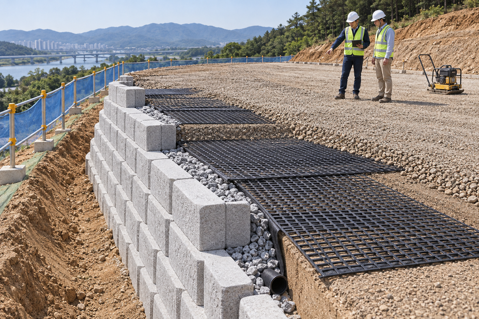
Retained AI-generated educational illustration from the source edition; not a real incident photograph, approved installation drawing or evidence of equipment suitability.
The scenario and record comparisons are fictional teaching examples, not records of real incidents, measurements, inspections, signatures or approvals.
| Item | Fictional scenario |
|---|---|
| Initial | Backfill is being placed behind a block face. |
| Change | Heavy compaction equipment approaches the face and several courses move. |
| Failure | Workers propose straightening the blocks and covering the layer. |
| Outcome | Damaged connections or increased lateral pressure can remain hidden and lead to further movement. |
| Barrier | Hold compaction and loading; compare layer loads, survey, reinforcement and drainage before a designed correction and reinspection. |
Why the controls matter
Straight facing does not demonstrate reinforcement pullout resistance, connection capacity, foundation bearing or overall slope stability. Keep reinforcement grade, length, orientation and connection evidence tied to each layer before concealment.
Compaction improves the fill but equipment weight and vibration can move an unfinished face. Use the design-specific lift thickness, moisture, equipment and face approach limits; final service loading does not authorize construction equipment on incomplete layers.
A drain pipe alone is not a drainage system. Inspect filter, pipe, gradient and outlet continuity and control external inflow. A finished-wall photograph cannot replace missing buried reinforcement or drainage inspections.
Decision sequence
| Step | Decision |
|---|---|
| Known | Heavy compaction equipment approaches the face and several courses move. |
| Unknown | Actual condition, extent of damage and suitability of layer and location, length and direction remain to be established. |
| Hold | Workers propose straightening the blocks and covering the layer. |
| Evidence | Link layer and location, length and direction, connection and overlap, damage inspection, seepage and loss, surcharge state to the affected equipment or work area. |
| Next | Hold compaction and loading; compare layer loads, survey, reinforcement and drainage before a designed correction and reinspection. |
5. Conditional decisions and common errors
| Condition | Action | Evidence | Proceed when |
|---|---|---|---|
| Facing moves | Stop loading and compaction | Layer survey and equipment | Cause resolved |
| Reinforcement unchecked | Do not cover layer | Grade direction and connection | Inspection complete |
| Outlet unknown | Hold concealment | Filter pipe outlet continuity | Drain path verified |
| Surcharge changes | Hold added load | Load and location review | Design accepts change |
Similar appearance, different evidence
The scenario and record comparisons are fictional teaching examples, not records of real incidents, measurements, inspections, signatures or approvals.
| Comparison | Supported decision | Insufficient basis |
|---|---|---|
| Condition | Layer survey and equipment | Facing moves has not been resolved. |
| Evidence | Filter pipe outlet continuity | A photograph or a completed-looking task without the relevant inspection record. |
| Release | Design accepts change | Completion of one step does not release the excluded tasks in section 2. |
6. Roles and responsibilities
| Role | Responsibility |
|---|---|
| Work supervisor | Assign the task boundary, stop authority, interfaces and emergency communication for reinforced soil segmental retaining wall construction. |
| Technical lead | Confirm Foundation and slope; Water and surcharge; Stage equipment loads; System design revision. Resolve design and manufacturer limits before work. |
| Authorized crew | Apply Block and grid grade; Lot and condition; Connection components; Lifting and storage. Stop when the working arrangement changes. |
| Inspector / receiving lead | Review Layer and location; Length and direction; Connection and overlap; Damage inspection. Transfer As-built layers; Drain outlets; Load and vehicle limits; Inspection owner. |
Role labels allocate responsibilities; they do not confer a legal qualification. Verify the competence, training and authority required for the actual task.
Record and handoff perspective
| Stage | Record controls | Verification |
|---|---|---|
| Review ground and loads | 1. Record foundation and slope2. Record water and surcharge3. Record stage equipment loads | 1. Water and surcharge2. Stage equipment loads3. System design revision |
| Inspect materials | 1. Record block and grid grade2. Record lot and condition3. Record connection components | 1. Lot and condition2. Connection components3. Lifting and storage |
| Place facing | 1. Record support and joints2. Record course alignment3. Record below-face exclusion | 1. Course alignment2. Below-face exclusion3. Access arrangement |
| Connect reinforcement | 1. Record layer and location2. Record length and direction3. Record connection and overlap | 1. Length and direction2. Connection and overlap3. Damage inspection |
| Hold rain or movement | 1. Record seepage and loss2. Record surcharge state3. Record movement trend | 1. Surcharge state2. Movement trend3. Repair and retest |
| Handoff wall | 1. Record as-built layers2. Record drain outlets3. Record load and vehicle limits | 1. Drain outlets2. Load and vehicle limits3. Inspection owner |
7. Hold points and record comparison
| Hold point | Evidence before release | Actual record |
|---|---|---|
| HP-0 Start | Construct a reinforced segmental block retaining wall, including accepted foundation, drainage, facing, specified reinforcement, staged backfill and handoff. | |
| HP-1 Prepare base and drains | Bearing and elevation; Weak-area disposition; Filter and pipe; Outlet inspection | |
| HP-2 Connect reinforcement | Layer and location; Length and direction; Connection and overlap; Damage inspection | |
| HP-3 Backfill and compact | Fill and moisture; Lift thickness; Equipment and setback; Density and movement | |
| HP-4 Handoff wall | As-built layers; Drain outlets; Load and vehicle limits; Inspection owner |
These are internal hold points, not issued permits. Recheck affected points after a change, fault or shift handoff; link the actual approval record.
Record comparison
The scenario and record comparisons are fictional teaching examples, not records of real incidents, measurements, inspections, signatures or approvals.
The boxes are static record prompts, not interactive or saved approvals. A tick does not establish suitability or permission to restart. Record the evidence, person, time and unresolved issues; retain the change history.
| Record | Insufficient | Record checklist |
|---|---|---|
| Review ground and loads | "Checked" without target, criteria or result | □ Foundation and slope□ Water and surcharge□ Stage equipment loads□ System design revision |
| Inspect materials | "Checked" without target, criteria or result | □ Block and grid grade□ Lot and condition□ Connection components□ Lifting and storage |
| Connect reinforcement | "Checked" without target, criteria or result | □ Layer and location□ Length and direction□ Connection and overlap□ Damage inspection |
| Handoff wall | "Checked" without target, criteria or result | □ As-built layers□ Drain outlets□ Load and vehicle limits□ Inspection owner |
8. Site checklist and emergency response
| Check | Result | Person / action |
|---|---|---|
| □ Review ground and loads: Foundation and slope | ||
| □ Prepare base and drains: Bearing and elevation | ||
| □ Inspect materials: Block and grid grade | ||
| □ Place facing: Support and joints | ||
| □ Connect reinforcement: Layer and location | ||
| □ Backfill and compact: Fill and moisture | ||
| □ Hold rain or movement: Seepage and loss | ||
| □ Handoff wall: As-built layers | ||
| □ Emergency access and handoff restrictions |
Stop work
Stop affected loading, compaction and access for bulging, increasing steps, settlement, washout, unexpected water or damaged reinforcement. Do not cover uninspected connections or apply changed surcharge without review.
Emergency response
Evacuate the face and retained-ground influence areas and control equipment. Do not remove displaced blocks or dig behind an unstable face to investigate. Call site emergency response and 911 as needed; recovery requires a stability and access plan.
9. Sources and review limits
Public-source review: 2026-10-13. Official regulation pages and specific technical references are distinguished below; no agency or manufacturer has approved this content.
| Source | Reviewed scope and limitation |
|---|---|
| OSHA 29 CFR 1926.651 | Excavation utilities, adjacent structures, water and competent-person inspections where applicable. |
| OSHA 29 CFR 1926.600 | Applicable construction equipment controls and maintenance support. |
| FHWA-RD-03-048 Chapter 2 | Archived 2003 background on internal/external stability, connections and deformation; no numeric design ratios adopted. |
| OSHA State Plans | Official overview of federal and State Plan jurisdiction and differing public-sector coverage, checked 2026-10-13. Individual state rules require a site-specific check. |
No site measurements, equipment manuals for the actual installation, inspection records or signed technical approvals were supplied. Confirm the applicable requirements and actual product instructions before use; record each criterion with its units, source and equipment or work-area ID.
10. PDF guidance and FAQ
PDF A covers basic task controls; B focuses on technical failures; C covers supervision, records and handover. The article has eight stages with four items per main cell; each PDF has six key stages with three items per main cell. P/S/R/A, measurements, confirmations and signatures remain blank for actual site assessment.
Content group
jsa-retainingwall-construction
Does a straight face prove acceptance?
No. Review foundation, reinforcement, connections, fill and drainage evidence together.
Can equipment drive directly on reinforcement?
Prevent damage and use the product/design cover and trafficking requirements.
Can a final photograph replace buried-work evidence?
No. Resolve the missing inspection through an approved verification plan.
Is one compactor setback valid everywhere?
No. Apply the approved construction-stage system and equipment limits.
Has a professional approved this JSA?
This reference material was written and revised with AI. It has not been verified or approved by a professional. Review by a suitably qualified professional and required site approval are necessary before field use.
11. Revision history and authorship
This reference material was written and revised with AI. It has not been verified or approved by a professional. Review by a suitably qualified professional and required site approval are necessary before field use.
Korean source created 2026-09-19. This US edition adapts the Korean source; earlier editorial revisions do not constitute professional approval of this edition.
| Date | Edition | Change | Review status |
|---|---|---|---|
| 2026-09-19 | Korean source v1.0 | Source editorial publication or revision; retained as provenance of the Korean edition. | Editorial record only; no professional approval of this US edition. |
| 2026-09-30 | Korean source v1.1 | Source editorial publication or revision; retained as provenance of the Korean edition. | Editorial record only; no professional approval of this US edition. |
| 2026-10-13 | 1.0 | US localization: preserve task judgments; replace Korean legal applicability with scoped US references. | AI editorial and output checks; no professional technical approval. |