Stopping the motor does not isolate the seal chamber. Trace suction, discharge and every flush, buffer, barrier or cooling connection before establishing the opening boundary.
This is reference content written and revised with AI. It has not been verified or approved by a professional. Review by a suitably qualified professional and required site authorization are necessary before use.
Stop conditions first
Do not open until fluid hazards, main/auxiliary isolation, drainage, pressure release and cooling are verified. Hold for reentry of fluid, damaged faces, incompatible materials, unknown settings or unverified startup fluid conditions.
1. US legal and technical basis
General-industry pump maintenance under applicable OSHA 1910.147 hazardous-energy and 1910.212 guarding requirements. Electrical and process-fluid hazards require their own applicable controls; no hazardous-process classification is inferred from the task name.
| Reference | Use and limit |
|---|---|
| OSHA 29 CFR 1910.147 | Covered maintenance requires all applicable energy isolation, stored-energy control, verification and controlled restoration. |
| OSHA 29 CFR 1910.212 | Applicable protection from exposed rotating parts; guards must be restored before operational handover. |
| John Crane Type 58U instructions | February 2026, selected pages 3–5: product setting datum, material/lubricant cautions, filled/vented seal chamber and isolated, drained decommissioning. Specific example only. |
| OSHA State Plans | Federal baseline and State Plan coverage reviewed. Confirm the applicable state program and employer coverage; this edition does not establish nationwide compliance. |
Determine whether Federal OSHA or an applicable State Plan governs the employer and work. Standards incorporated into a regulation must be read in their legally applicable edition. Other NFPA/ANSI guidance and manufacturer instructions have distinct roles; they are not automatically federal law.
2. Scope and required inputs
Included
Replace a mechanical seal in an isolated centrifugal pump, inspect and assemble the specified parts, restore auxiliary piping and hand over for separately controlled testing and startup.
Separate assessment
Live adjustment, opening pressurized equipment, unidentified fluid, transfer of settings between seal types and unassessed hazardous-process decontamination are excluded.
| Input | Evidence needed |
|---|---|
| Identify pump and seal | Fluid/temp/pressure; Flush/buffer/barrier paths; Seal model/direction; Motor/backflow sources |
| Isolate drain and cool | Lockout boundary; Trapped sections/drains; Fluid removal/temperature; Rotation prevention |
| Dismantle and withdraw | Stored-force method; Hand/body position; Fragment/part count; Residual-fluid state |
| Dispose and hand over | Waste/cleanup; Assembly/test evidence; Fluid/temp/pressure limits; Operations receiver |
Selected public official provisions were checked on October 13, 2026. This is not a complete legal audit. No actual equipment manual, site measurements, engineering calculations, product certification or professional technical approval was supplied. Full paid NFPA/ANSI standards and state/local amendments were not reviewed. Check actual equipment, jurisdiction and project requirements before use.
Select task-appropriate eye, hand, foot, skin and hearing protection from the exposure assessment. Where respiratory protection is necessary, use the applicable respiratory-protection program; PPE does not replace isolation, guarding, support or ventilation.
3. Eight-stage JSA
| Job stage | Hazards and effects | Failure factors | Controls | Site verification | P | S | R | A |
|---|---|---|---|---|---|---|---|---|
| 1. Identify pump and seal | 1. Hazardous-fluid release2. Hot-fluid burn3. Wrong seal assembly4. Unexpected rotation | 1. Fluid misidentified2. Auxiliary supply missed3. Drawing mismatched4. Energy sources incomplete | 1. Verify fluid/SDS2. Trace all auxiliary systems3. Match seal and drawing4. Identify every energy source | 1. Fluid/temp/pressure2. Flush/buffer/barrier paths3. Seal model/direction4. Motor/backflow sources | ||||
| 2. Isolate drain and cool | 1. Trapped-fluid spray2. Pressure returns3. Chemical contact4. Backflow rotation | 1. Closed valve trusted2. Gauge zero overextended3. Drain/cleaning unverified4. Discharge backflow remains | 1. Isolate complete boundary2. Verify safe pressure release3. Drain/decontaminate/cool4. Prevent startup/backflow | 1. Lockout boundary2. Trapped sections/drains3. Fluid removal/temperature4. Rotation prevention | ||||
| 3. Prepare opening support | 1. Residual-fluid exposure2. Component falls3. Tool slips4. Flammable vapor | 1. PPE/collection absent2. Part weight unknown3. Wrong puller/tool4. Atmosphere unassessed | 1. Match exposure protection2. Support parts before release3. Use specified tools4. Assess ventilation/fire hazards | 1. SDS and PPE2. Part/support rating3. Access/tool condition4. Vapor/collection controls | ||||
| 4. Dismantle and withdraw | 1. Spring force releases2. Finger crush3. Sharp fragments4. Residual liquid spills | 1. Sequence changed2. Parts pulled by hand3. Broken faces unsecured4. Drain assumed complete | 1. Follow model sequence2. Use appropriate extraction3. Contain broken parts4. Collect remaining fluid | 1. Stored-force method2. Hand/body position3. Fragment/part count4. Residual-fluid state | ||||
| 5. Inspect and assemble seal | 1. Face damage2. Elastomer degradation3. Wrong operating length4. Shaft/bolt damage | 1. Dirt or impact2. Material/lube mismatch3. Old marks trusted4. Torque improvised | 1. Protect clean seal faces2. Match fluid/materials3. Use exact setting method4. Follow fastening sequence | 1. Face condition2. Material/lubricant match3. Datum/settings/direction4. Shaft/fastening evidence | ||||
| 6. Restore auxiliaries/guards | 1. Lost cooling2. Piping leak3. Dry-running damage4. Rotating-part contact | 1. Flush misconnected2. Pipe support absent3. Fill/vent omitted4. Guard not restored | 1. Match piping to plan2. Verify support/connections3. Establish startup fluid4. Restore coupling guard | 1. Auxiliary flow path2. Pipe strain/connections3. Filled/vented condition4. Guard/tools clear | ||||
| 7. Control test and faults | 1. Fluid spray injury2. Rotating contact3. Repressurized opening4. Repeated seal failure | 1. Leak felt by hand2. Live adjustment3. Re-isolation omitted4. Cause ignored | 1. Control test access2. Keep hands from running parts3. Re-isolate before rework4. Resolve cause and retest | 1. Test/leak method2. Guarded boundary3. Pressure/cooling recheck4. Cause/correction record | ||||
| 8. Dispose and hand over | 1. Contaminated waste exposure2. Unresolved leak used3. Auxiliary system off4. Wrong shift operation | 1. Waste mixed2. Test limits unreported3. Fluid conditions omitted4. Restore authority unclear | 1. Segregate waste safely2. Record checks and holds3. Transfer auxiliary conditions4. Authorize operating transition | 1. Waste/cleanup2. Assembly/test evidence3. Fluid/temp/pressure limits4. Operations receiver |
Actual risk assessments, measurements, checks, approvals and signatures have not been performed. Keep unverified fields blank and link the actual site records. P/S/R/A mean likelihood, severity, site-method risk and site-defined acceptance/authorization; a score cannot waive a required control.
4. Failure mechanisms and hypothetical case
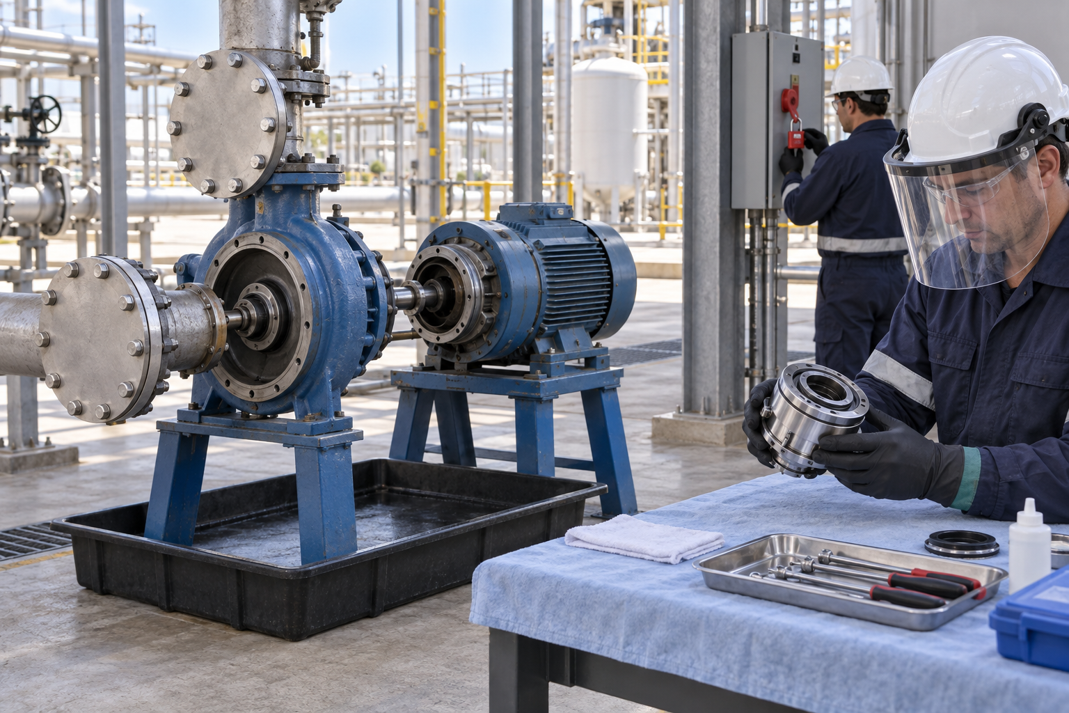
The retained illustration is an AI-generated educational image from the Korean source. It is not an actual incident photograph, approved drawing, equipment certification or proof that the depicted arrangement is safe.
A small auxiliary line can supply hazardous pressure independently of the main piping. One zero gauge does not establish the safe state of trapped chambers, blocked drains or possible refill paths.
A new seal can leak after contamination, impact, incorrect material selection or wrong working length. Distinguish component-seal settings from cartridge setting-device sequences and follow the exact product drawing.
Liquid-lubricated seals need the specified filled and vented condition before startup. Connected piping does not prove the correct fluid path, flow or cooling function.
Repeated leakage can involve shaft/sleeve condition, alignment, piping strain and auxiliary fluid conditions. Stop and re-isolate before inspection; do not treat a live tightening attempt as a repair.
Hypothetical decision example
Hypothetical example: main valves are closed and a pump gauge reads zero, but the seal auxiliary system has another supply and the chamber drain path is unverified. Opening is held while the complete boundary, trapped fluid and cooling state are established.
The example is fictional; no incident, measurement, inspection or approval is asserted.
Task flow: Identify pump and seal → Isolate drain and cool → Prepare opening support → Dismantle and withdraw → Inspect and assemble seal → Restore auxiliaries/guards → Control test and faults → Dispose and hand over
5. Hold and proceed decisions
| Condition | Action | Evidence | Proceed when |
|---|---|---|---|
| Opening boundary unknown | Hold disassembly | Main/auxiliary isolation and drainage | Safe opening verified |
| Seal setting uncertain | Check exact product drawing | Type, datum and material record | Assembly basis confirmed |
| Piping restored | Verify fluid condition | Direction, fill, vent and cooling | Startup conditions met |
| Leak during test | Stop and re-isolate | Leak conditions and corrected retest | Fault disposition accepted |
Similar observation, different conclusion
| Observation | Supported conclusion | What remains unresolved |
|---|---|---|
| Motor stopped | Drive motion stopped | Fluid/auxiliary energy may remain |
| New seal installed | Replacement part fitted | Settings and startup fluid unproved |
6. Roles and supervision
| Role | Responsibility |
|---|---|
| Work supervisor | Coordinate identify pump and seal, affected operations, stop signals and stage transitions. |
| Technical/equipment reviewer | Verify Fluid/temp/pressure, Flush/buffer/barrier paths, actual instructions and unresolved technical limits. |
| Task crew | Apply the stated controls, report changes and keep actual checks and signatures factual. |
| Inspector/test lead | Connect Auxiliary flow path, Pipe strain/connections to the required acceptance criteria. |
| Receiving authority | Accept the recorded restrictions, Fluid/temp/pressure limits, Operations receiver, and follow-up ownership. |
These are responsibility examples, not invented statutory credentials. Verify actual competence, training and authority for the assigned work.
Supervision and handover controls
| Stage | Management controls | Evidence |
|---|---|---|
| Plan review | 1. Assign technical owner2. Close task-specific questions3. Verify fluid/SDS | 1. Fluid/temp/pressure2. Flush/buffer/barrier paths3. Motor/backflow sources |
| Competence | 1. Verify required competence2. Assign stop authority3. Isolate complete boundary | 1. Lockout boundary2. Training and task briefing3. Rotation prevention |
| Prestart evidence | 1. Inspect actual equipment2. Link evidence to this stage3. Follow model sequence | 1. Stored-force method2. Hand/body position3. Residual-fluid state |
| Change control | 1. Stop and secure the area2. Review affected controls3. Control test access | 1. Test/leak method2. Guarded boundary3. Cause/correction record |
| Shift handover | 1. Identify remaining restrictions2. Confirm receiving responsibility3. Segregate waste safely | 1. Waste/cleanup2. Assembly/test evidence3. Operations receiver |
| Closeout | 1. Record defect disposition2. Archive factual evidence3. Segregate waste safely | 1. Waste/cleanup2. Assembly/test evidence3. Operations receiver |
7. Hold points and record quality
| Hold point | Evidence before release | Actual record |
|---|---|---|
| HP-0 Start | Replace a mechanical seal in an isolated centrifugal pump, inspect and assemble the specified parts, restore auxiliary piping and hand over for separately controlled testing and startup. | |
| HP-1 Isolate drain and cool | Lockout boundary; Trapped sections/drains; Fluid removal/temperature; Rotation prevention | |
| HP-2 Dismantle and withdraw | Stored-force method; Hand/body position; Fragment/part count; Residual-fluid state | |
| HP-3 Control test and faults | Test/leak method; Guarded boundary; Pressure/cooling recheck; Cause/correction record | |
| HP-4 Dispose and hand over | Waste/cleanup; Assembly/test evidence; Fluid/temp/pressure limits; Operations receiver |
Hold points are internal evidence gates. They do not establish that a statutory permit exists or has been approved. Recheck affected gates after changes, faults and shift handover.
Record comparison - hypothetical templates
The 16 boxes below identify record elements, not completed checks or approvals. They are static symbols. Link equipment/location, date, actual findings and the separate record reference; preserve unresolved items.
| Record | Insufficient entry | Required record elements |
|---|---|---|
| Identify pump and seal | "Checked" without supporting facts | □ Fluid/temp/pressure□ Flush/buffer/barrier paths□ Seal model/direction□ Motor/backflow sources |
| Prepare opening support | "Checked" without supporting facts | □ SDS and PPE□ Part/support rating□ Access/tool condition□ Vapor/collection controls |
| Inspect and assemble seal | "Checked" without supporting facts | □ Face condition□ Material/lubricant match□ Datum/settings/direction□ Shaft/fastening evidence |
| Control test and faults | "Checked" without supporting facts | □ Test/leak method□ Guarded boundary□ Pressure/cooling recheck□ Cause/correction record |
8. Pre-work checks and emergency response
| Check required | Result | Checker/action |
|---|---|---|
| Identify pump and seal: Fluid/temp/pressure | ||
| Isolate drain and cool: Lockout boundary | ||
| Prepare opening support: SDS and PPE | ||
| Dismantle and withdraw: Stored-force method | ||
| Inspect and assemble seal: Face condition | ||
| Restore auxiliaries/guards: Auxiliary flow path | ||
| Control test and faults: Test/leak method | ||
| Dispose and hand over: Waste/cleanup |
Stop work
Do not open until fluid hazards, main/auxiliary isolation, drainage, pressure release and cooling are verified. Hold for reentry of fluid, damaged faces, incompatible materials, unknown settings or unverified startup fluid conditions.
Emergency response
Stop the test from a safe position and keep people away from rotating parts and escaping fluid. Arrange safe main and auxiliary isolation, drainage and cooling before approach. For hazardous-fluid exposure, serious burns or injection injury, activate the site response and call 911 as needed; provide the fluid/SDS, pump location and pressure/temperature state. Do not locate leaks by hand or open the chamber during the response.
9. Official sources and review limits
Official public-source check: October 13, 2026. The review concerns the selected passages described below, not endorsement of this article.
| Official source | Checked scope and limit |
|---|---|
| OSHA 29 CFR 1910.147 | Covered maintenance requires all applicable energy isolation, stored-energy control, verification and controlled restoration. |
| OSHA 29 CFR 1910.212 | Applicable protection from exposed rotating parts; guards must be restored before operational handover. |
| John Crane Type 58U instructions | February 2026, selected pages 3–5: product setting datum, material/lubricant cautions, filled/vented seal chamber and isolated, drained decommissioning. Specific example only. |
| OSHA State Plans | Federal baseline and State Plan coverage reviewed. Confirm the applicable state program and employer coverage; this edition does not establish nationwide compliance. |
Selected public official provisions were checked on October 13, 2026. This is not a complete legal audit. No actual equipment manual, site measurements, engineering calculations, product certification or professional technical approval was supplied. Full paid NFPA/ANSI standards and state/local amendments were not reviewed. Check actual equipment, jurisdiction and project requirements before use.
This is reference content written and revised with AI. It has not been verified or approved by a professional. Review by a suitably qualified professional and required site authorization are necessary before use.
10. PDF use and frequently asked questions
PDF A summarizes core controls; B emphasizes technical failures; C covers supervision, records and handover. Each uses six stages from or aligned with the eight-stage body. All actual risk, measurement, check and signature fields are blank. Use a separate linked record where more space is needed.
Are closed main valves enough?
No. Verify all auxiliary supplies, trapped sections, rotation sources and the safe condition at the opening.
Can old shaft marks set the replacement?
Use them only as a reference; verify the exact new seal drawing and setting sequence.
Does a new seal eliminate the cause?
Not necessarily. Examine shaft, alignment, piping forces and support-fluid conditions.
May a liquid-lubricated seal run briefly dry?
Meet the actual seal and pump startup requirements. Do not use an empty pump run as a generic rotation check.
Has a professional approved this JSA?
This is reference content written and revised with AI. It has not been verified or approved by a professional. Review by a suitably qualified professional and required site authorization are necessary before use.
11. Authorship and revision history
This is reference content written and revised with AI. It has not been verified or approved by a professional. Review by a suitably qualified professional and required site authorization are necessary before use.
| Date/version | Editorial history | Technical approval |
|---|---|---|
| September 19, 2026 / Korean v1.1 | Korean source: retained previously displayed draft version and source-check date; no professional review record asserted. | Professional technical approval not performed |
| September 26, 2026 / Korean v1.2 | Korean source: revised task decisions, record checklists, JSA and three PDFs; editorial/source and layout checks. | Professional technical approval not performed |
| October 14, 2026 / US v1.0 | US localization: Retains main-versus-auxiliary isolation, chamber drain uncertainty and seal-type-specific settings. Adds US maintenance/guarding context and the limited John Crane liquid-lubricated example without transferring dimensions or lubricants. | Not performed |
Source topic: https://smartjsabridge.com/ko/case-study/jsa-pumpseal-replacement
Content group: jsa-pumpseal-replacement