The load path runs through pipe, clamp, hanger, bracket, anchor and supporting structure. Verify the current load state and every relevant connection before releasing temporary supports.
This is reference content written and revised with AI. It has not been verified or approved by a professional. Review by a suitably qualified professional and required site authorization are necessary before use.
Stop conditions first
Hold drilling or attachment for unknown loads, substrate, embedded services or support function. Stop transfer for sag, anchor movement, weld defects or unstable temporary support.
1. US legal and technical basis
Construction installation of utility-pipe supports in an industrial facility. Applicable OSHA 1926 access, silica and hot-work controls govern the methods; structural capacity, anchor installation and thermal movement require the actual approved design and product instructions. Maintenance classification needs a separate 1910 assessment.
| Reference | Use and limit |
|---|---|
| OSHA 29 CFR 1926.1153 | Applicable construction concrete drilling requires a compliant silica-control method, including the specified Table 1 system or exposure-assessment alternative; generic dust collection alone is not a compliance finding. |
| OSHA 29 CFR 1926.352 | Selected construction welding/heating fire prevention, combustible protection and required post-work watch conditions. |
| Spirax Sarco Pipe Expansion and Support | Selected public explanation of thermal expansion and support functions. Tutorial examples and spacing values are not site design values. |
| OSHA State Plans | Federal baseline and State Plan coverage reviewed. Confirm the applicable state program and employer coverage; this edition does not establish nationwide compliance. |
Determine whether Federal OSHA or an applicable State Plan governs the employer and work. Standards incorporated into a regulation must be read in their legally applicable edition. Other NFPA/ANSI guidance and manufacturer instructions have distinct roles; they are not automatically federal law.
2. Scope and required inputs
Included
Install and inspect specified hangers, supports and anchors, adjust cold positions and transfer an identified pipe load from temporary to permanent support in the reviewed sequence.
Separate assessment
Unplanned support removal from operating pipes, unauthorized structural drilling/welding, arbitrary spring settings and pressure testing/hot operation are excluded.
| Input | Evidence needed |
|---|---|
| Plan load and function | Test/operating loads; Structure/anchor basis; Fixed/guide/spring detail; Current support state |
| Control access and energy | Platform/fall controls; Fluid/pressure/temperature; Exclusion zone; Isolation evidence |
| Drill weld and attach | Dust-control method; Fire/watch conditions; Welding/return setup; Temporary support |
| Transfer operating limits | Test/additional loads; Anchor/weld records; Settings/restrictions; Area and receiver |
Selected public official provisions were checked on October 13, 2026. This is not a complete legal audit. No actual equipment manual, site measurements, engineering calculations, product certification or professional technical approval was supplied. Full paid NFPA/ANSI standards and state/local amendments were not reviewed. Check actual equipment, jurisdiction and project requirements before use.
Select task-appropriate eye, hand, foot, skin and hearing protection from the exposure assessment. Where respiratory protection is necessary, use the applicable respiratory-protection program; PPE does not replace isolation, guarding, support or ventilation.
3. Eight-stage JSA
| Job stage | Hazards and effects | Failure factors | Controls | Site verification | P | S | R | A |
|---|---|---|---|---|---|---|---|---|
| 1. Plan load and function | 1. Pipe falls2. Substrate fails3. Expansion restrained4. Existing support collapses | 1. Test water omitted2. Structure data absent3. Support types confused4. Current path unknown | 1. Review all load states2. Verify complete load path3. Identify support functions4. Inspect existing condition | 1. Test/operating loads2. Structure/anchor basis3. Fixed/guide/spring detail4. Current support state | ||||
| 2. Control access and energy | 1. Fall from height2. Hot-pipe burn3. Dropped object strike4. Unexpected process force | 1. Platform absent2. Pressure/temp unknown3. Work below overlaps4. Isolation omitted | 1. Provide safe access2. Verify pipe energy state3. Exclude area below4. Apply required isolation | 1. Platform/fall controls2. Fluid/pressure/temperature3. Exclusion zone4. Isolation evidence | ||||
| 3. Inspect base and parts | 1. Anchor pulls out2. Member breaks3. Embedded service hit4. Sharp-edge cut | 1. Wrong anchor/substrate2. Mixed hardware3. Rebar/services unlocated4. Damaged part used | 1. Match anchor to design2. Verify identified components3. Confirm drilling location4. Inspect edges/tools | 1. Anchor/substrate match2. Material and defects3. Embedded conflicts4. Location approval | ||||
| 4. Drill weld and attach | 1. Silica exposure2. Spark fire3. Electric shock4. Bracket falls | 1. Dust controls inadequate2. Combustibles exposed3. Welding return unsuitable4. Temporary support absent | 1. Use compliant drill controls2. Apply hot-work precautions3. Verify welding circuit4. Support bracket during fixing | 1. Dust-control method2. Fire/watch conditions3. Welding/return setup4. Temporary support | ||||
| 5. Assemble and adjust | 1. Finger crush2. Pipe shifts3. Parts fall4. Unequal support load | 1. Hands align gap2. Temporary support removed3. Loose hardware above people4. Height sequence changed | 1. Align using suitable tools2. Retain temporary support3. Secure loose components4. Follow reviewed adjustment | 1. Hands/body position2. Temporary stability3. Parts retention4. Height/contact/load share | ||||
| 6. Inspect and transfer | 1. Connection fails2. Pipe sags3. Thermal movement blocked4. Spring set incorrectly | 1. Cure/check incomplete2. Contact gap missed3. Slide clamped rigid4. Lock sequence wrong | 1. Verify anchor/weld evidence2. Transfer in measured stages3. Check movement function4. Match spring/lock procedure | 1. Inspection/cure records2. Transfer movement/sag3. Guide/slide clearance4. Spring setting/locks | ||||
| 7. Hold shift or changed load | 1. Pipe collapse2. Stored stress release3. Smoldering fire4. Unauthorized restart | 1. Load state unknown2. Supports removed together3. Fire watch ended early4. Isolation not handed over | 1. Keep stable support2. Review changed load/sequence3. Complete fire precautions4. Control restoration authority | 1. Current load/change2. Temporary support plan3. Fire-watch disposition4. Isolation/restart record | ||||
| 8. Transfer operating limits | 1. Added-load overload2. Hidden joint defect3. Lost movement function4. Unprotected access | 1. Fill/insulation omitted2. Inspection record lost3. Lock status unknown4. Barrier removed early | 1. Specify later load limits2. Link connection evidence3. Record movement/lock state4. Restore safe work area | 1. Test/additional loads2. Anchor/weld records3. Settings/restrictions4. Area and receiver |
Actual risk assessments, measurements, checks, approvals and signatures have not been performed. Keep unverified fields blank and link the actual site records. P/S/R/A mean likelihood, severity, site-method risk and site-defined acceptance/authorization; a score cannot waive a required control.
4. Failure mechanisms and hypothetical case
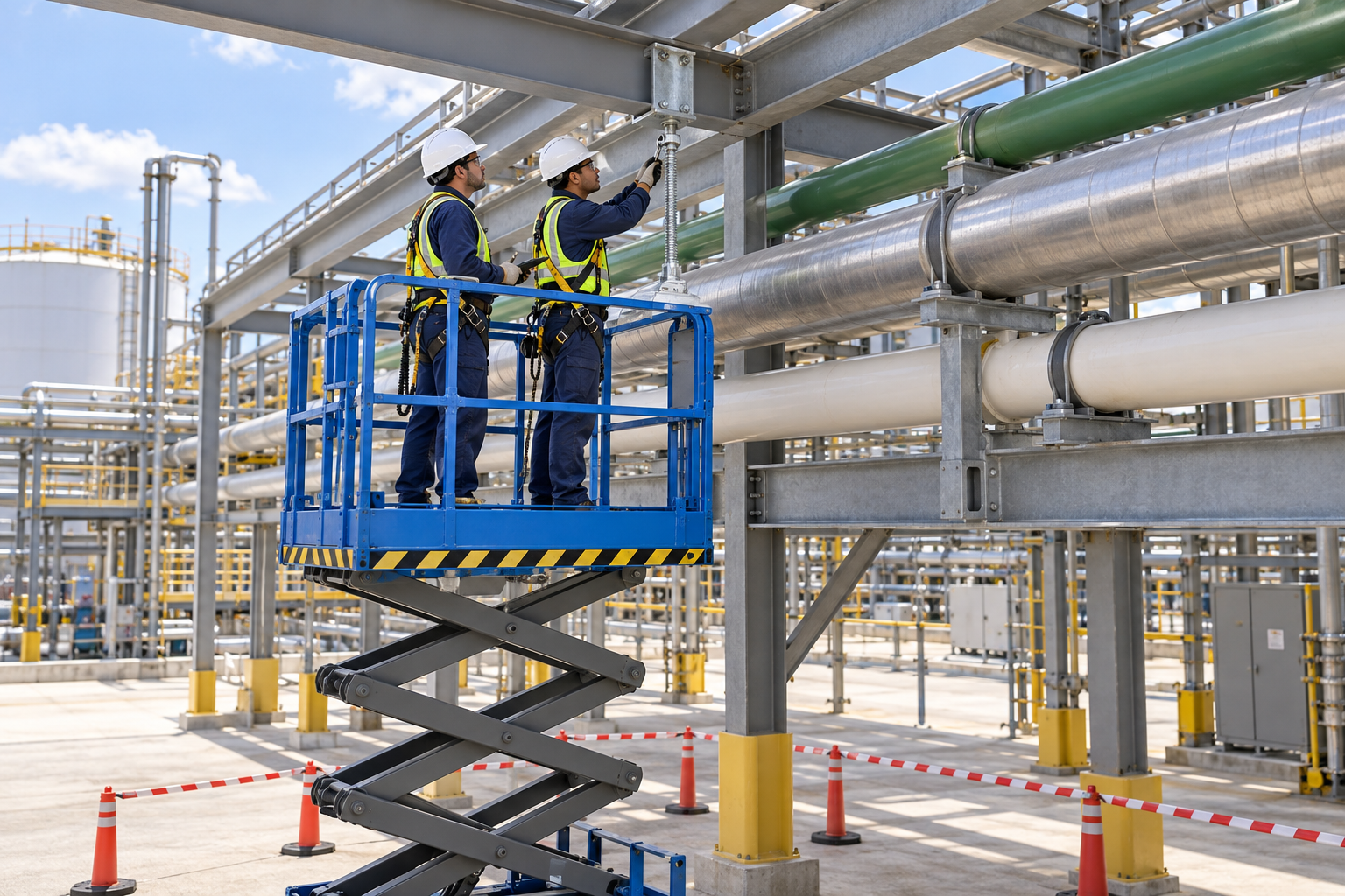
The retained illustration is an AI-generated educational image from the Korean source. It is not an actual incident photograph, approved drawing, equipment certification or proof that the depicted arrangement is safe.
Empty, water-filled test, insulated and operating pipe states can impose different weight and movement. Coordinate filling and other work with the installation crew instead of relying on the earlier empty-pipe assessment.
An installed anchor or finished weld is not evidence that inspection and required cure conditions have passed. Transfer load in the reviewed stages while checking contact, movement and load sharing.
Fixed points, guides, slides and spring supports have different functions. Rigidly tying every support can defeat designed thermal movement; shipping/test locks follow the actual spring-support procedure.
Moving a hole around reinforcing steel changes edge distances, anchor geometry and the load path. Stop for design review instead of selecting a nearby location by convenience.
Hypothetical decision example
Hypothetical example: a test crew fills a pipe with water before the installer releases temporary supports, but the change is not communicated. The empty-pipe assessment is no longer sufficient. Temporary support is retained while the current load and transfer conditions are reviewed.
The example is fictional; no incident, measurement, inspection or approval is asserted.
Task flow: Plan load and function → Control access and energy → Inspect base and parts → Drill weld and attach → Assemble and adjust → Inspect and transfer → Hold shift or changed load → Transfer operating limits
5. Hold and proceed decisions
| Condition | Action | Evidence | Proceed when |
|---|---|---|---|
| Pipe filled for test | Hold load transfer | Current contents and design load | Changed load checked |
| Anchor/substrate unknown | Do not drill/attach | Actual product and structure evidence | Attachment accepted |
| Temporary support removal | Check inspection/cure first | Load sharing and transfer sequence | Transfer released |
| Guide movement blocked | Hold operating handover | Movement and lock instructions | Designed function restored |
Similar observation, different conclusion
| Observation | Supported conclusion | What remains unresolved |
|---|---|---|
| Anchor installed | Attachment work is present | Cure, inspection and capacity unproved |
| Empty pipe supported | That load state was supported | Test/operating states need review |
6. Roles and supervision
| Role | Responsibility |
|---|---|
| Work supervisor | Coordinate plan load and function, affected operations, stop signals and stage transitions. |
| Technical/equipment reviewer | Verify Test/operating loads, Structure/anchor basis, actual instructions and unresolved technical limits. |
| Task crew | Apply the stated controls, report changes and keep actual checks and signatures factual. |
| Inspector/test lead | Connect Inspection/cure records, Transfer movement/sag to the required acceptance criteria. |
| Receiving authority | Accept the recorded restrictions, Settings/restrictions, Area and receiver, and follow-up ownership. |
These are responsibility examples, not invented statutory credentials. Verify actual competence, training and authority for the assigned work.
Supervision and handover controls
| Stage | Management controls | Evidence |
|---|---|---|
| Plan review | 1. Assign technical owner2. Close task-specific questions3. Review all load states | 1. Test/operating loads2. Structure/anchor basis3. Current support state |
| Competence | 1. Verify required competence2. Assign stop authority3. Provide safe access | 1. Platform/fall controls2. Training and task briefing3. Isolation evidence |
| Prestart evidence | 1. Inspect actual equipment2. Link evidence to this stage3. Use compliant drill controls | 1. Dust-control method2. Fire/watch conditions3. Temporary support |
| Change control | 1. Stop and secure the area2. Review affected controls3. Keep stable support | 1. Current load/change2. Temporary support plan3. Isolation/restart record |
| Shift handover | 1. Identify remaining restrictions2. Confirm receiving responsibility3. Specify later load limits | 1. Test/additional loads2. Anchor/weld records3. Area and receiver |
| Closeout | 1. Record defect disposition2. Archive factual evidence3. Specify later load limits | 1. Test/additional loads2. Anchor/weld records3. Area and receiver |
7. Hold points and record quality
| Hold point | Evidence before release | Actual record |
|---|---|---|
| HP-0 Start | Install and inspect specified hangers, supports and anchors, adjust cold positions and transfer an identified pipe load from temporary to permanent support in the reviewed sequence. | |
| HP-1 Control access and energy | Platform/fall controls; Fluid/pressure/temperature; Exclusion zone; Isolation evidence | |
| HP-2 Drill weld and attach | Dust-control method; Fire/watch conditions; Welding/return setup; Temporary support | |
| HP-3 Hold shift or changed load | Current load/change; Temporary support plan; Fire-watch disposition; Isolation/restart record | |
| HP-4 Transfer operating limits | Test/additional loads; Anchor/weld records; Settings/restrictions; Area and receiver |
Hold points are internal evidence gates. They do not establish that a statutory permit exists or has been approved. Recheck affected gates after changes, faults and shift handover.
Record comparison - hypothetical templates
The 16 boxes below identify record elements, not completed checks or approvals. They are static symbols. Link equipment/location, date, actual findings and the separate record reference; preserve unresolved items.
| Record | Insufficient entry | Required record elements |
|---|---|---|
| Plan load and function | "Checked" without supporting facts | □ Test/operating loads□ Structure/anchor basis□ Fixed/guide/spring detail□ Current support state |
| Inspect base and parts | "Checked" without supporting facts | □ Anchor/substrate match□ Material and defects□ Embedded conflicts□ Location approval |
| Assemble and adjust | "Checked" without supporting facts | □ Hands/body position□ Temporary stability□ Parts retention□ Height/contact/load share |
| Hold shift or changed load | "Checked" without supporting facts | □ Current load/change□ Temporary support plan□ Fire-watch disposition□ Isolation/restart record |
8. Pre-work checks and emergency response
| Check required | Result | Checker/action |
|---|---|---|
| Plan load and function: Test/operating loads | ||
| Control access and energy: Platform/fall controls | ||
| Inspect base and parts: Anchor/substrate match | ||
| Drill weld and attach: Dust-control method | ||
| Assemble and adjust: Hands/body position | ||
| Inspect and transfer: Inspection/cure records | ||
| Hold shift or changed load: Current load/change | ||
| Transfer operating limits: Test/additional loads |
Stop work
Hold drilling or attachment for unknown loads, substrate, embedded services or support function. Stop transfer for sag, anchor movement, weld defects or unstable temporary support.
Emergency response
Stop loading or transfer and clear the area below and beside a shifting pipe. Do not body-brace it or remove another support to relieve stress. Arrange designed temporary stabilization and process isolation from safe positions. For falling pipe, hot-fluid release, fire or serious injury, activate the site response and call 911 as needed. Keep the current load and isolation state documented for recovery personnel.
9. Official sources and review limits
Official public-source check: October 13, 2026. The review concerns the selected passages described below, not endorsement of this article.
| Official source | Checked scope and limit |
|---|---|
| OSHA 29 CFR 1926.1153 | Applicable construction concrete drilling requires a compliant silica-control method, including the specified Table 1 system or exposure-assessment alternative; generic dust collection alone is not a compliance finding. |
| OSHA 29 CFR 1926.352 | Selected construction welding/heating fire prevention, combustible protection and required post-work watch conditions. |
| Spirax Sarco Pipe Expansion and Support | Selected public explanation of thermal expansion and support functions. Tutorial examples and spacing values are not site design values. |
| OSHA State Plans | Federal baseline and State Plan coverage reviewed. Confirm the applicable state program and employer coverage; this edition does not establish nationwide compliance. |
Selected public official provisions were checked on October 13, 2026. This is not a complete legal audit. No actual equipment manual, site measurements, engineering calculations, product certification or professional technical approval was supplied. Full paid NFPA/ANSI standards and state/local amendments were not reviewed. Check actual equipment, jurisdiction and project requirements before use.
This is reference content written and revised with AI. It has not been verified or approved by a professional. Review by a suitably qualified professional and required site authorization are necessary before use.
10. PDF use and frequently asked questions
PDF A summarizes core controls; B emphasizes technical failures; C covers supervision, records and handover. Each uses six stages from or aligned with the eight-stage body. All actual risk, measurement, check and signature fields are blank. Use a separate linked record where more space is needed.
Does support of empty pipe prove test-water capacity?
No. Evaluate the full test-water and other applicable loads through the complete support path.
Can temporary supports come out after tightening?
Only after required inspection, cure and staged transfer conditions are verified.
Should every support prevent all movement?
No. Preserve the designed fixed, guide, sliding and spring functions.
Are spring shipping locks always removed immediately?
Follow the model-specific installation, test and operating transition sequence.
Has a professional approved this JSA?
This is reference content written and revised with AI. It has not been verified or approved by a professional. Review by a suitably qualified professional and required site authorization are necessary before use.
11. Authorship and revision history
This is reference content written and revised with AI. It has not been verified or approved by a professional. Review by a suitably qualified professional and required site authorization are necessary before use.
| Date/version | Editorial history | Technical approval |
|---|---|---|
| September 19, 2026 / Korean v1.1 | Korean source: retained previously displayed draft version and source-check date; no professional review record asserted. | Professional technical approval not performed |
| September 26, 2026 / Korean v1.2 | Korean source: revised task decisions, record checklists, JSA and three PDFs; editorial/source and layout checks. | Professional technical approval not performed |
| October 13, 2026 / US v1.0 | US localization: Preserves water-fill change case, complete load path, staged transfer and support-function distinctions. Adds US construction silica/hot-work context without importing tutorial spacing, anchor torque, cure or spring-setting values. | Not performed |
Source topic: https://smartjsabridge.com/ko/case-study/jsa-pipehanger-installation
Content group: jsa-pipehanger-installation