An outage notice does not establish the safe state at the identified work location. Line and phase identity, all sources, automatic reclosing, possible backfeed and induction must be addressed by the qualified crew and controlling operator before approach as deenergized.
This is reference content written and revised with AI. It has not been verified or approved by a professional. Review by a suitably qualified professional and site authorization are required before use.
Stop before starting
Stop if line identity, operator clearance, qualified testing, required grounding, adjacent-line protection, conductor support or rescue arrangements are unverified. Hold for communication loss, support movement or weather outside the accepted plan.
1. Legal and technical scope
| Basis | Scope and limits |
|---|---|
| OSHA 1910.269 | Covered utility work, qualifications, deenergization and protective grounding. |
| OSHA 1926.962 | Construction protective grounding and narrowly conditioned exceptions. |
Resolve the actual work scope: covered utility operation and maintenance uses 1910.269; electric transmission/distribution construction uses Part 1926 Subpart V. Deenergization and grounding are required under the applicable provisions before treating the line as deenergized. A grounding exception requires the regulation's specific demonstration and conditions, not a crew preference. Qualified personnel must establish electrical boundaries, grounding and restoration under the operator's procedure. Check State Plan requirements.
2. Scope and required inputs
Included work
Planned replacement of an overhead power-line insulator by qualified utility personnel after electrical clearance, testing and protective grounding under the applicable utility procedure, with separate conductor support and controlled restoration.
Separate assessment
Energized replacement, unreviewed conductor-tension release, structural redesign and unqualified approach to power lines are excluded. This reference is not a switching or grounding instruction.
| Required input | Evidence to obtain |
|---|---|
| Plan line and crew | Pole phase and line; Clearance responsibility; Load and access plan; Crew and rescue readiness |
| Secure ground and access | Traffic and exclusion; Adjacent circuit status; Access position; Weather decision |
| Establish electrical state | Source and operator record; Qualified test record; Grounding arrangement; Clearance and restrictions |
| Accept access and support | Pole and foundation; Access and rescue checks; Temporary load path; Equipment limitations |
No actual equipment model, SDS, site measurements, design calculations or authorization record was supplied. Product-specific limits and methods must be verified before use. Federal OSHA is a baseline within its scope; determine the applicable State Plan and local requirements. Manufacturer guidance is not government approval; an incorporated standard differs from voluntary guidance. No nationwide-compliance or expert-approval claim is made.
3. Eight-stage JSA
| Job stage | Hazards and effects | Failure factors | Technical and procedural controls | Site verification | P | S | R | A |
|---|---|---|---|---|---|---|---|---|
| 1. Plan line and crew | 1. Wrong circuit contact2. Unplanned reclose3. Support failure4. Delayed rescue | 1. Line ID unclear2. Sources omitted3. Forces unknown4. Rescue unplanned | 1. Reconcile line identity2. Coordinate operator control3. Review conductor support4. Assign qualified crew | 1. Pole phase and line2. Clearance responsibility3. Load and access plan4. Crew and rescue readiness | ||||
| 2. Secure ground and access | 1. Traffic strike2. Dropped hardware3. Adjacent-line contact4. Weather loss of control | 1. Drop zone shared2. People below3. Boundary guessed4. Wind ignored | 1. Control traffic and drop area2. Protect adjacent exposures3. Use qualified boundaries4. Apply weather limits | 1. Traffic and exclusion2. Adjacent circuit status3. Access position4. Weather decision | ||||
| 3. Establish electrical state | 1. Backfeed shock2. Induced voltage3. Reenergization4. Grounding exposure | 1. Outage notice trusted2. Source missed3. Reclose uncontrolled4. Method improvised | 1. Use operator procedure2. Verify identified circuit3. Apply required grounding4. Reconcile clearance status | 1. Source and operator record2. Qualified test record3. Grounding arrangement4. Clearance and restrictions | ||||
| 4. Accept access and support | 1. Pole failure2. Elevated fall3. Conductor movement4. Equipment overload | 1. Pole condition unknown2. Rescue absent3. Load path incomplete4. Bucket capacity assumed | 1. Inspect pole and access2. Use approved fall system3. Establish designed support4. Verify actual equipment use | 1. Pole and foundation2. Access and rescue checks3. Temporary load path4. Equipment limitations | ||||
| 5. Replace component | 1. Conductor release2. Insulator fracture3. Dropped parts4. Incorrect assembly | 1. Load still on fitting2. Wrong rating3. Pins unsecured4. Hardware mismatched | 1. Verify supported load2. Match electrical mechanical type3. Control parts and tools4. Inspect specified assembly | 1. Support acceptance2. Insulator identity3. Pins and hardware4. Assembly inspection | ||||
| 6. Coordinate restoration | 1. Unexpected energization2. Unstable conductor3. Grounds unaccounted4. Crew still exposed | 1. Stages merged2. Support removed early3. Ground log incomplete4. Crew status missing | 1. Separate release stages2. Verify conductor position3. Reconcile every ground4. Obtain operator authority | 1. Mechanical acceptance2. Support release3. Ground and tool count4. Crew clearance status | ||||
| 7. Hold changed conditions | 1. Electrical exposure2. Support collapse3. Uncontrolled movement4. Conflicting switching | 1. Communication lost2. Support shifts3. Weather worsens4. Clearance uncertain | 1. Stop and maintain boundaries2. Notify controlling authority3. Stabilize by approved plan4. Reverify before release | 1. Change and location2. Electrical clearance state3. Support condition4. Restart authority | ||||
| 8. Close and hand over | 1. Unresolved defect2. Wrong normal state3. Later electrical exposure4. Lost work record | 1. Defect hidden2. Status assumed3. Grounds not reconciled4. Recipient unspecified | 1. Record final configuration2. Transfer unresolved holds3. Confirm operator status4. Close crew records | 1. Component inspection2. Ground reconciliation3. Operating status4. Recipient and restrictions |
P = likelihood; S = severity; R = risk under the site method; A = site-defined acceptance/authorization. These actual assessment cells are blank. A low score never overrides a missing safeguard or a legal or manufacturer restriction.
4. Fictional scenario and failure mechanisms
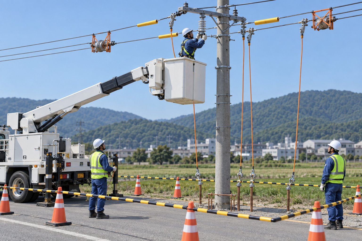
This illustration provides educational context. It is not an actual incident photograph or evidence of equipment suitability; any AI-generated depiction is illustrative only.
The scenario and record comparisons are fictional teaching examples, not records of real incidents, measurements, inspections, signatures or approvals.
| Stage | Fictional situation |
|---|---|
| Initial situation | A fictional crew receives a planned outage notice. |
| Changed condition | At the pole, the actual work-point identity and electrical safe-state records are incomplete. |
| Failure path | The crew considers the notice sufficient to start insulator replacement. |
| Possible outcome | Unexpected voltage could cause electrical injury and a fall, while an unsupported conductor could move. |
| Prevention barrier | Hold the task until qualified personnel establish electrical controls at the correct location, then independently verify the mechanical support and access plan. |
Failure mechanisms
An outage notice does not establish the safe state at the identified work location. Line and phase identity, all sources, automatic reclosing, possible backfeed and induction must be addressed by the qualified crew and controlling operator before approach as deenergized.
An insulator provides electrical separation and may carry mechanical load. Electrical clearance does not release conductor tension. The approved temporary load path must support the actual conductor forces before hardware is disturbed; an access bucket is not automatically a lifting support.
Component replacement, temporary-support removal, ground removal and energization are separate releases. Reconcile all crews, tools, grounding records and mechanical inspection with the clearance holder and system operator. No universal approach distance or generic ground arrangement is supplied here.
Work sequence: Plan line and crew → Secure ground and access → Establish electrical state → Accept access and support → Replace component → Coordinate restoration → Hold changed conditions → Close and hand over. This is a teaching flow, not a device drawing or a complete operating procedure.
5. Conditional decisions and common errors
| Situation | Required action | Evidence | Proceed when |
|---|---|---|---|
| Work-point identity uncertain | Hold approach and switching task | Line, pole and phase reconciliation | Identity confirmed |
| Electrical clearance incomplete | Treat as energized | Operator and grounding records | Safe state established |
| Conductor support uncertain | Do not disturb hardware | Approved load-path review | Support accepted |
| Restoration requested | Reconcile every crew | Grounds, tools and clearance status | Operator authorizes |
Similar observations, different decisions
The scenario and record comparisons are fictional teaching examples, not records of real incidents, measurements, inspections, signatures or approvals.
| Observation | Insufficient conclusion | Required distinction |
|---|---|---|
| Outage scheduled | Administrative plan | Actual safe state unproved |
| Line deenergized | Electrical condition | Mechanical load remains |
| New insulator fitted | Component changed | Energization not released |
6. Roles and responsibilities
| Role | Responsibility |
|---|---|
| Work supervisor | Confirm pole phase and line and the task scope, resources, interfaces and stop authority. |
| Qualified technical reviewer | Review traffic and exclusion, model limits, compatibility and unresolved technical conditions within assigned competence. |
| Work crew | Apply the listed controls, report changes and stop when evidence or safeguards are missing. |
| Inspector / assessor | Record actual support acceptance and other relevant checks; do not mark unverified conditions as accepted. |
| Handover authority | Reconcile component inspection, restrictions and outstanding actions before the next task. Role labels do not establish a legal credential. |
Supervision and handover focus
| Stage | Management action | Evidence |
|---|---|---|
| Plan line and crew | 1. Record pole phase and line2. Record clearance responsibility3. Record load and access plan | 1. Pole phase and line2. Clearance responsibility3. Load and access plan |
| Establish electrical state | 1. Record source and operator record2. Record qualified test record3. Record grounding arrangement | 1. Source and operator record2. Qualified test record3. Grounding arrangement |
| Accept access and support | 1. Record pole and foundation2. Record access and rescue checks3. Record temporary load path | 1. Pole and foundation2. Access and rescue checks3. Temporary load path |
| Replace component | 1. Record support acceptance2. Record insulator identity3. Record pins and hardware | 1. Support acceptance2. Insulator identity3. Pins and hardware |
| Hold changed conditions | 1. Record change and location2. Record electrical clearance state3. Record support condition | 1. Change and location2. Electrical clearance state3. Support condition |
| Close and hand over | 1. Record component inspection2. Record ground reconciliation3. Record operating status | 1. Component inspection2. Ground reconciliation3. Operating status |
7. Hold points and record comparison
| Hold point | Evidence before release | Actual approval |
|---|---|---|
| HP-0 Scope | Planned replacement of an overhead power-line insulator by qualified utility personnel after electrical clearance, testing and protective grounding under the applicable utility procedure, with separate conductor support and controlled restoration. | |
| HP-1 Establish electrical state | Source and operator record; Qualified test record; Grounding arrangement; Clearance and restrictions | |
| HP-2 Accept access and support | Pole and foundation; Access and rescue checks; Temporary load path; Equipment limitations | |
| HP-3 Hold changed conditions | Change and location; Electrical clearance state; Support condition; Restart authority | |
| HP-4 Close and hand over | Component inspection; Ground reconciliation; Operating status; Recipient and restrictions |
Hold points are internal project checks. They are not universal statutory permits and do not grant work permission. Reassess after defects, changed conditions and shift changes.
Record comparison
The scenario and record comparisons are fictional teaching examples, not records of real incidents, measurements, inspections, signatures or approvals.
The boxes are static record prompts, not interactive or saved approvals. A tick does not establish suitability or permission to restart. Record the evidence, person, time and unresolved issues; retain the change history.
| Record | Insufficient record | Record checklist |
|---|---|---|
| Plan line and crew | Only marked “OK” | □ Pole phase and line□ Clearance responsibility□ Load and access plan□ Crew and rescue readiness |
| Accept access and support | Only marked “OK” | □ Pole and foundation□ Access and rescue checks□ Temporary load path□ Equipment limitations |
| Hold changed conditions | Only marked “OK” | □ Change and location□ Electrical clearance state□ Support condition□ Restart authority |
| Close and hand over | Only marked “OK” | □ Component inspection□ Ground reconciliation□ Operating status□ Recipient and restrictions |
8. Site checklist and emergency response
| Site check | Actual result | Person / action |
|---|---|---|
| Plan line and crew: Pole phase and line; Clearance responsibility; Load and access plan; Crew and rescue readiness | ||
| Secure ground and access: Traffic and exclusion; Adjacent circuit status; Access position; Weather decision | ||
| Establish electrical state: Source and operator record; Qualified test record; Grounding arrangement; Clearance and restrictions | ||
| Accept access and support: Pole and foundation; Access and rescue checks; Temporary load path; Equipment limitations | ||
| Replace component: Support acceptance; Insulator identity; Pins and hardware; Assembly inspection | ||
| Coordinate restoration: Mechanical acceptance; Support release; Ground and tool count; Crew clearance status | ||
| Hold changed conditions: Change and location; Electrical clearance state; Support condition; Restart authority | ||
| Close and hand over: Component inspection; Ground reconciliation; Operating status; Recipient and restrictions |
Stop work
Stop if line identity, operator clearance, qualified testing, required grounding, adjacent-line protection, conductor support or rescue arrangements are unverified. Hold for communication loss, support movement or weather outside the accepted plan.
Emergency response
Keep people outside electrical and conductor-fall boundaries. Activate the utility emergency and rescue plan through the controlling operator. Only qualified responders using the established electrical safe-state and rescue arrangements may approach the exposure.
9. Sources and review limits
Public-source access/review: 2026-10-13.
| Official source | Reviewed scope and limits |
|---|---|
| OSHA 1910.269 | Covered utility work, qualifications, deenergization and protective grounding. |
| OSHA 1926.962 | Construction protective grounding and narrowly conditioned exceptions. |
No actual equipment model, SDS, site measurements, design calculations or authorization record was supplied. Product-specific limits and methods must be verified before use. Federal OSHA is a baseline within its scope; determine the applicable State Plan and local requirements. Manufacturer guidance is not government approval; an incorporated standard differs from voluntary guidance. No nationwide-compliance or expert-approval claim is made.
10. PDF guidance and FAQ
PDF A covers basic task controls; B focuses on technical failures; C covers supervision, records and handover. The article has eight stages with four items per main cell; each PDF has six key stages with three items per main cell. P/S/R/A, measurements, confirmations and signatures remain blank for actual site assessment.
PDFs are complementary six-stage extracts. Apply all eight body stages and the actual equipment/site procedure.
Does an outage notice permit replacement?
No. The qualified crew and system operator must establish and verify the actual electrical safe state and required grounding.
Can the access bucket carry the conductor load?
Only if the equipment and approved plan specifically permit that use and the actual loads; do not assume it.
Who releases energization?
The designated controlling authority after the applicable clearance, crew, grounding and mechanical-restoration requirements are reconciled.
Has a professional verified or approved this document?
No. Public sources and editorial, layout and consistency checks were reviewed using AI. No site inspection or professional technical approval has been performed. Obtain appropriate professional review before use.
11. Revision history and authorship
This is reference content written and revised with AI. It has not been verified or approved by a professional. Review by a suitably qualified professional and site authorization are required before use.
| Date | Version | Change | Review status |
|---|---|---|---|
| 2026-10-13 | US 1.0 | New US edition from assigned Korean source; task decisions, records and PDFs localized. | AI editorial review; no professional technical approval |
Korean edition revision history: 2026-09-20 (v1.0): initial article, sources, fictional analysis and PDF editorial checks; 2026-09-23 (v1.1): task decisions, record checklist, JSA and three PDF variants revised. These are editorial records, not professional technical approval. US v1.0 adapts the earlier edition to United States requirements and terminology.
Site reviewers must add their actual qualifications, scope, date and approval only after the review occurs.