Replacement of an identified hydraulic hose assembly on stationary isolated equipment using an approved equivalent assembly, mechanically supported loads and verified control of pressure on both sides.
Stop for unknown circuit connections, unsupported loads, uncertain residual or returning pressure, incompatible fittings, damaged assemblies or leakage during testing. Never use hands, gloves or cloth to feel for a pressurized leak.
Reference content written and revised with AI. It has not been verified or approved by a professional. Review by a suitably qualified professional and site approval are required before use.
1. Legal and technical scope
OSHA 1910.147 applies to covered general-industry servicing where unexpected start or stored energy could cause injury. Its stored-energy and verification provisions require control of residual energy and continued verification when reaccumulation is possible. Construction work needs its applicable Part 1926 analysis; this document does not treat 1910.147 as a universal construction rule.
Determine Federal OSHA or the applicable OSHA-approved State Plan, including public/private employer coverage. State Plans must be at least as effective and can impose different or additional requirements. The actual activity determines construction versus general-industry scope. Manufacturer instructions, consensus standards, project design and site approvals have distinct roles; this page is not a finding of nationwide compliance.
| Basis | Application and limits |
|---|---|
| OSHA 1910.147 | Servicing isolation, stored-energy control, verification and release provisions. |
| Parker Hose Products Safety Guide 4400-B.1 | Selected assembly compatibility, routing and failure-response guidance, Rev A October 30, 2015. Actual product instructions govern; no universal torque or bend limit adopted. |
2. Scope and required inputs
Included: Replacement of an identified hydraulic hose assembly on stationary isolated equipment using an approved equivalent assembly, mechanically supported loads and verified control of pressure on both sides.
Separate review: Pressurized tightening or replacement, accumulator disassembly or charging, field hose crimping, circuit redesign and work beneath unsupported mobile booms require separate procedures.
| Input | Required evidence |
|---|---|
| Identify circuit and assembly | Circuit and hose IDs; Both connection locations; Assembly and seal specification; Fluid and equipment data |
| Control residual pressure | Segment pressure evidence; Accumulator and valve paths; Both hose ends assessed; Continued energy control |
| Fit and route assembly | Part and seal identity; Fastening method and result; Bend twist and clamp condition; Motion and heat clearance |
| Record and hand over | Installed parts and date; Test and inspection results; Follow-up owner and timing; Receiving authority and holds |
Confirm fluid, pressure and temperature ratings, fitting and seal type, assembly length, bend and routing limits, clamp requirements and fastening method from actual equipment and hose instructions. Establish protected testing conditions and full movement clearance without exposing people to injection or crushing hazards.
3. Eight-stage JSA
P = likelihood; S = severity; R = risk under the site method; A = acceptance or authorization as defined by the site. Leave these blank until actual assessment and control verification. A low score does not override a legal requirement, product limit or unreleased hold point.
| Job stage | Hazards and effects | Failure factors | Required controls | Site verification | P | S | R | A |
|---|---|---|---|---|---|---|---|---|
| 1. Identify circuit and assembly | 1. Wrong-line release2. Incompatible seal leak3. Unexpected load motion4. Fluid exposure | 1. Hose ends not traced2. Thread fit accepted alone3. Circuit drawing outdated4. Fluid identity missing | 1. Trace both hose connections2. Match approved full assembly3. Review actual circuit and loads4. Confirm fluid hazards | 1. Circuit and hose IDs2. Both connection locations3. Assembly and seal specification4. Fluid and equipment data | ||||
| 2. Stop isolate and support | 1. Load-drop crush2. Unexpected pump start3. Stored mechanical movement4. Electrical restart | 1. Hydraulics hold load alone2. Remote start remains3. Support unsuitable4. Isolation unverified | 1. Lower or mechanically support2. Isolate all energy sources3. Control associated movement4. Verify authorized isolation | 1. Mechanical support basis2. Energy points and locks3. Remote and automatic sources4. Safe-state verification | ||||
| 3. Control residual pressure | 1. Fluid injection2. Hose whip3. Trapped-fluid spray4. Pressure returns during work | 1. Pump stop treated as zero2. Check valves overlooked3. One gauge used alone4. Load or accumulator recharges | 1. Follow segment release method2. Address both sides and traps3. Control reaccumulation4. Verify before opening | 1. Segment pressure evidence2. Accumulator and valve paths3. Both hose ends assessed4. Continued energy control | ||||
| 4. Remove and protect ends | 1. Residual-fluid contact2. Contamination damage3. Dropped component injury4. Wrong connection restored | 1. Joint opened too soon2. Ports left uncovered3. Assembly unsupported4. End labels lost | 1. Confirm safe opening state2. Contain fluid and cap ports3. Support assembly removal4. Retain connection identity | 1. Release verification2. Clean caps and containment3. Removed assembly condition4. End labels and orientation | ||||
| 5. Fit and route assembly | 1. Hose abrasion failure2. Fitting seal failure3. Kink or twist rupture4. Moving-part contact | 1. Wrong seal or assembly2. Bend limit exceeded3. Hose twisted on tightening4. Motion clearance unchecked | 1. Use approved parts and method2. Maintain specified bend route3. Control twist and supports4. Check full movement envelope | 1. Part and seal identity2. Fastening method and result3. Bend twist and clamp condition4. Motion and heat clearance | ||||
| 6. Restore and test | 1. Fluid injection2. Unexpected equipment motion3. Hose burst strike4. Undetected leakage | 1. Hands used for leak search2. People remain in test area3. Guards left open4. Test conditions improvised | 1. Restore required safeguards2. Clear and control test area3. Use protected detection method4. Apply authorized test procedure | 1. Test boundary and controls2. Operating conditions recorded3. Leak and movement observations4. No personnel in hazard path | ||||
| 7. Hold and correct faults | 1. Live-tightening injury2. Repeated hose failure3. Load descent during rework4. Damaged assembly reused | 1. Leak treated as minor2. Cause not determined3. Isolation not repeated4. Failed hose patched | 1. Stop and repeat isolation2. Reverify support and pressure3. Resolve seal and routing cause4. Replace rejected assemblies | 1. Fault location and conditions2. Cause and approved correction3. Support and pressure recheck4. Protected retest evidence | ||||
| 8. Record and hand over | 1. Incorrect replacement history2. Missed early leak3. Unsafe operating release4. Fluid residue slip | 1. Part identity omitted2. Follow-up not assigned3. Test mistaken for approval4. Cleanup incomplete | 1. Link installed assembly record2. Assign required follow-up3. Transfer operating limits4. Remove fluid and waste | 1. Installed parts and date2. Test and inspection results3. Follow-up owner and timing4. Receiving authority and holds |
4. Hypothetical scenario and failure mechanisms
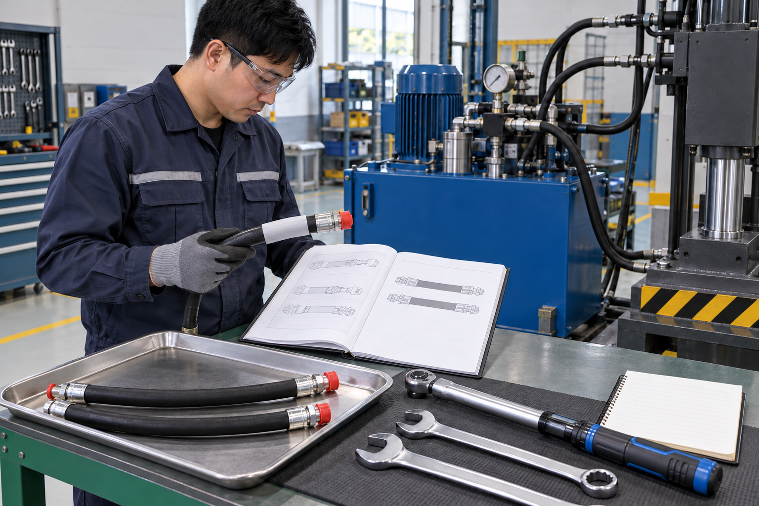 Retained source illustration: an AI-generated educational concept, not a real incident photograph or evidence of equipment suitability.
The following scenario, comparisons and example records are hypothetical teaching material. They do not reproduce actual incidents, measurements, signatures or approvals.
| Item | Hypothetical situation |
|---|---|
| Initial state | A replacement hose passes a stationary visual check. |
| Change | During movement it contacts a frame edge and fluid appears at a fitting. |
| Failure path | The crew proposes tightening the joint while the pump continues running. |
| Possible harm | Pressurized fluid can penetrate skin while a moving load or hose can strike the worker. |
| Barrier | Stop, isolate and support the equipment, verify residual-pressure control and correct the assembly, seal and moving-route problem before a protected retest. |
Pump shutdown does not prove pressure removal. Accumulators, check valves, trapped sections and load-induced pressure can retain or regenerate energy. Verify the actual hose segment at both ends by the approved procedure; do not loosen a fitting to discover whether pressure remains.
Threads that engage may still have the wrong sealing geometry or material. Match the complete approved assembly and mating connection, including fluid compatibility, operating conditions and required seals. Do not patch a failed hose or substitute an unapproved mixed assembly.
A static loop does not demonstrate full movement clearance. Pressure, temperature and machine motion change hose position and length. Check the permitted routing, bend, twist, abrasion protection and supports throughout the intended movement envelope.
Testing and hands-on correction are separate work states. Restore the required safeguards and exclusion for controlled testing. If leakage or interference appears, return to isolation, pressure control and mechanical support before inspection or adjustment.
| Decision | Reason and evidence |
|---|---|
| Known facts | During movement it contacts a frame edge and fluid appears at a fitting. |
| Unresolved | The crew proposes tightening the joint while the pump continues running. |
| Hold reason | Stop for unknown circuit connections, unsupported loads, uncertain residual or returning pressure, incompatible fittings, damaged assemblies or leakage during testing. Never use hands, gloves or cloth to feel for a pressurized leak. |
| Evidence needed | Part and seal identity; Fastening method and result; Bend twist and clamp condition; Motion and heat clearance. |
| Next decision | Stop, isolate and support the equipment, verify residual-pressure control and correct the assembly, seal and moving-route problem before a protected retest. |
5. Conditional decisions and common errors
| Condition | Action | Evidence | Proceed when |
|---|---|---|---|
| Pressure uncertain | Do not open either connection. | Trapped energy and both-side verification. | Safe segment state verified. |
| Wrong fitting or seal | Hold assembly installation. | Approved pairing and specification. | Compatible complete assembly. |
| Hose touches frame | Stop and review moving route. | Full movement and support check. | Required clearance maintained. |
| Leak during test | Stop and return to isolation. | Cause, correction and protected retest. | Defect resolved. |
| Comparison | Situation A | Situation B |
|---|---|---|
| Gauge reads zero | The relevant trapped sections and reaccumulation paths are verified. | One remote gauge is assumed to cover both hose ends. |
| Hose fits at rest | The specified assembly clears the full movement envelope. | Only the parked position is checked. |
6. Roles and responsibilities
| Role | Responsibility |
|---|---|
| Work supervisor | Confirm scope, task sequence, exclusion and stop authority. Coordinate identify circuit and assembly with affected operations. |
| Technical reviewer | Resolve the actual design and equipment limits: Circuit and hose IDs; Both connection locations; Assembly and seal specification; Fluid and equipment data. |
| Work crew | Perform control residual pressure using the approved procedure; report any mismatch before proceeding. |
| Inspector / assessor | Verify Test boundary and controls; Operating conditions recorded; Leak and movement observations; No personnel in hazard path. Record what was actually checked and what remains unresolved. |
| Release / receiving authority | Confirm Installed parts and date; Test and inspection results; Follow-up owner and timing; Receiving authority and holds. Transfer restrictions and the next permitted stage. |
These are responsibility examples, not invented statutory credentials. Meet the actual training, competent-person, qualified-person and licensing requirements for the assigned work. Anyone may raise a hazard and request a stop; only the designated authority may release the affected stage after evidence is reviewed.
7. Hold points and record comparison
| Hold point | Evidence before release | Confirmation / approval |
|---|---|---|
| HP-0 Start | Scope, jurisdiction, equipment identity, responsible people and emergency arrangements. | |
| HP-1 Control residual pressure | Segment pressure evidence; Accumulator and valve paths; Both hose ends assessed; Continued energy control | |
| HP-2 Fit and route assembly | Part and seal identity; Fastening method and result; Bend twist and clamp condition; Motion and heat clearance | |
| HP-3 Hold and correct faults | Fault location and conditions; Cause and approved correction; Support and pressure recheck; Protected retest evidence | |
| HP-4 Record and hand over | Installed parts and date; Test and inspection results; Follow-up owner and timing; Receiving authority and holds |
Hold points are internal evidence gates. They do not replace statutory permits or actual signatures. Recheck affected gates after a change, abnormal event or shift transfer. The blank record must identify the evidence, person, time, limits and release scope.
| Record | Insufficient record | Record checklist |
|---|---|---|
| Circuit | Pump stopped | □ Segment pressure evidence□ Accumulator and valve paths□ Both hose ends assessed□ Continued energy control |
| Assembly | Threads fit | □ Circuit and hose IDs□ Both connection locations□ Assembly and seal specification□ Fluid and equipment data |
| Routing | Looks loose enough | □ Part and seal identity□ Fastening method and result□ Bend twist and clamp condition□ Motion and heat clearance |
| Recovery | Joint tightened | □ Fault location and conditions□ Cause and approved correction□ Support and pressure recheck□ Protected retest evidence |
The □ boxes are static prompts, not saved or interactive approvals. Each checks one record element. A tick alone does not establish suitability or permission to restart. Link equipment IDs and supporting records; retain unresolved matters and the earlier record when conditions change.
8. Site checklist and emergency response
| Check item | Result | Person / action |
|---|---|---|
| Circuit and hose IDs | ||
| Mechanical support basis | ||
| Segment pressure evidence | ||
| Release verification | ||
| Part and seal identity | ||
| Test boundary and controls | ||
| Fault location and conditions | ||
| Installed parts and date | ||
| Emergency arrangements and unresolved restrictions communicated |
Stop work: Stop for unknown circuit connections, unsupported loads, uncertain residual or returning pressure, incompatible fittings, damaged assemblies or leakage during testing. Never use hands, gloves or cloth to feel for a pressurized leak.
Emergency response: Treat suspected high-pressure fluid injection as an immediate medical emergency, even if the skin mark is small. Call 911 or obtain immediate emergency care and identify the fluid and SDS to responders. Do not squeeze or cut the wound. Stop equipment from a safe position, restrict the area and have designated personnel control pressure and loads before rescue access.
9. Sources and review limits
Official-source review date: October 14, 2026. The following review is limited to the public provisions or selected manufacturer material identified below. It does not establish that any authority approved this article or the actual installation.
- OSHA 1910.147: Servicing isolation, stored-energy control, verification and release provisions.
- Parker Hose Products Safety Guide 4400-B.1: Selected assembly compatibility, routing and failure-response guidance, Rev A October 30, 2015. Actual product instructions govern; no universal torque or bend limit adopted.
- OSHA State Plans: jurisdiction and coverage overview; identify the actual state program before use.
Paid consensus standards and site-specific calculations, manuals, inspection records and product certificates were not independently obtained or verified unless specifically identified. Korean legal citations remain in the preserved Korean source as source history; they are not represented as US legal duties.
10. PDF guidance and FAQ
PDF A covers basic task controls; B examines technical failures; C focuses on supervision, evidence and handover. Each has six rows and three items per main cell. They are complementary extracts: apply all eight body stages and the applicable site procedure. An omitted stage is not permission to omit its controls. PDF HP-0 through HP-4 are worksheet labels; match the event, evidence and authority rather than assuming they match another permit by number.
P/S/R/A, actual measurements, confirmations and signatures remain blank. The PDFs are uncompleted reference worksheets, not issued work permits.
Content group ID: jsa-hydraulic-hose-replacement
Does stopping the pump remove all pressure?
No. Trapped sections, accumulators, valves and loads can retain or regenerate pressure. Verify the actual segment by its approved procedure.
Can a gloved hand find a small leak?
No. Do not expose a hand, glove or cloth to a pressurized jet. Use a protected detection method specified for the equipment.
Is a matching thread enough?
No. Confirm sealing geometry, materials, fluid compatibility and the complete approved assembly.
Can a leaking fitting be tightened during testing?
No. Stop and return to verified isolation, pressure control and load support before hands-on correction.
Has a professional verified or approved this document?
No. This is AI-assisted reference material. Editorial and layout checks are not a physical inspection or professional technical approval. Obtain qualified professional review and required site approval before use.
11. Revision history and authorship
Reference content written and revised with AI. It has not been verified or approved by a professional. Review by a suitably qualified professional and site approval are required before use.
This system has not physically inspected the equipment, structures, ground, atmosphere or worksite. The document does not replace legal advice, manufacturer procedures, engineering design, inspection certificates, qualification evidence, the site risk assessment or an actual work permit.
Before use, a suitably qualified and authorized person must review the actual equipment, loads, methods, protection, inspection and emergency arrangements and resolve open issues. Record the real reviewer, organization, qualifications, delegated authority, reviewed documents, date, signature, exclusions and conditions of approval separately.
| Date | Version | Change | Review status |
|---|---|---|---|
| 2026-09-23 | 1.0 | Korean source revision retained in the source snapshot. | Historical editorial status; not US professional approval. |
| 2026-10-14 | US 1.0 | US localization of the assigned Korean source; task reasoning, educational image and history retained; US scope and sources reviewed. | AI-assisted editorial work; professional approval not performed. |