Prior drying and a dry exterior do not establish the current condition inside a mold or conductor. Moisture can return after storage or exposure. Distinguish preparation before material placement from a fault after material has been added; do not improvise heating, water addition or re-ignition.
This is reference content written and revised with AI. It has not been verified or approved by a professional. Review by a suitably qualified professional and site authorization are required before use.
Stop before starting
Stop excavation or rod driving for unknown utilities or unstable ground. Hold activation for moisture, contamination, mismatched components, poor mold closure or missing fire controls. Keep defective joints exposed and identified until disposition.
1. Legal and technical scope
| Basis | Scope and limits |
|---|---|
| OSHA 1926.651 | Utility investigation and safe location as excavation approaches installations; other excavation safeguards remain applicable. |
| nVent ERICO installation and inspection guidance | Manufacturer reference for compatible components and moisture/contamination hazards; verify actual product instructions and US installation requirements. |
Construction excavation requires applicable 1926.651 utility-location and excavation controls. Fire, electrical and exposure requirements depend on the actual work. The selected manufacturer instructions govern its bonding system; they are not a nationwide grounding design or acceptance criterion. Determine State Plan, adopted electrical code and project requirements. No universal grounding resistance value or generic drying temperature is supplied.
2. Scope and required inputs
Included work
Utility investigation, grounding electrode/conductor placement, approved exothermic connection, cooling, joint inspection, pre-burial records, planned backfill and grounding-system tests.
Separate assessment
Disconnecting operating protective grounds, driving rods near unlocated utilities, unapproved mold/material combinations and improvised reheating or re-ignition are excluded.
| Required input | Evidence to obtain |
|---|---|
| Review design and utilities | Utility evidence; Excavation and rod points; Operating ground state; Drawing and joint ID |
| Prepare hot-work area | Combustible zone; Material and SDS; Worker and ventilation; Alarm and fire response |
| Excavate and place | Location verification; Exposed installations; Ground and access; Electrode position |
| Check mold combination | Dryness evidence; Mold and conductor ID; Closure and clamp; Material condition |
No actual equipment model, SDS, site measurements, design calculations or authorization record was supplied. Product-specific limits and methods must be verified before use. Federal OSHA is a baseline within its scope; determine the applicable State Plan and local requirements. Manufacturer guidance is not government approval; an incorporated standard differs from voluntary guidance. No nationwide-compliance or expert-approval claim is made.
3. Eight-stage JSA
| Job stage | Hazards and effects | Failure factors | Technical and procedural controls | Site verification | P | S | R | A |
|---|---|---|---|---|---|---|---|---|
| 1. Review design and utilities | 1. Power-line strike2. Pipe leak3. Grounding loss4. Wrong connection | 1. Utilities unlocated2. Survey incomplete3. Operating impact missed4. Drawing mismatch | 1. Investigate utilities2. Check survey extent3. Review ground boundary4. Identify connection points | 1. Utility evidence2. Excavation and rod points3. Operating ground state4. Drawing and joint ID | ||||
| 2. Prepare hot-work area | 1. Burn or fire2. Degraded material3. Fume exposure4. Delayed response | 1. Combustibles remain2. Storage improper3. Position unreviewed4. Response unclear | 1. Set fire controls2. Check stored materials3. Plan shielding and air4. Provide response means | 1. Combustible zone2. Material and SDS3. Worker and ventilation4. Alarm and fire response | ||||
| 3. Excavate and place | 1. Utility contact2. Excavation collapse3. Rod strike4. Unauthorized access | 1. Records not verified2. Ground unstable3. People in strike zone4. Opening unprotected | 1. Verify utility locations2. Apply excavation plan3. Control rod-work zone4. Protect open excavation | 1. Location verification2. Exposed installations3. Ground and access4. Electrode position | ||||
| 4. Check mold combination | 1. Hot-metal spatter2. Weak connection3. Mold separation4. Material misuse | 1. Moisture present2. Conductor mismatch3. Clamp loose4. Wrong material | 1. Follow current preparation2. Match approved combination3. Inspect mold closure4. Follow product storage | 1. Dryness evidence2. Mold and conductor ID3. Closure and clamp4. Material condition | ||||
| 5. Control heat cycle | 1. Thermal burn2. Spark fire3. Fume inhalation4. Early opening spatter | 1. People too close2. Fuel remains3. Breathing zone exposed4. Cooling omitted | 1. Use specified shielding2. Maintain fire controls3. Protect breathing zone4. Follow cooling procedure | 1. Worker position2. Fire watch conditions3. Air and wind4. Cooling and opening | ||||
| 6. Inspect before burial | 1. Poor continuity2. Conductor damage3. Joint concealed4. Test potential | 1. Defect ignored2. Corrosion mismatch3. Location unrecorded4. Test scope wrong | 1. Inspect joint criteria2. Check material condition3. Record photos and location4. Follow inspection sequence | 1. Joint acceptance2. Conductor condition3. Pre-burial record4. Test stage and boundary | ||||
| 7. Hold and rework | 1. Spatter recurrence2. Defect hidden3. Protective ground lost4. Repeat failure | 1. Condensation ignored2. Defect buried3. Ground removed casually4. Cause unresolved | 1. Hold activation2. Mark defective joint3. Preserve system boundary4. Verify accepted correction | 1. Current material state2. Joint hold identity3. Isolation and impact4. Cause and reinspection | ||||
| 8. Test and hand over | 1. Uninspected burial2. Wrong acceptance3. Backfill damage4. Unresolved system use | 1. Checks omitted2. Test setup missing3. Conductor disturbed4. Limits not passed on | 1. Reconcile joint records2. Record test conditions3. Inspect restoration4. Transfer use restrictions | 1. Photos and location2. Measurement arrangement3. Backfill and test stages4. Criteria and recipient |
P = likelihood; S = severity; R = risk under the site method; A = site-defined acceptance/authorization. These actual assessment cells are blank. A low score never overrides a missing safeguard or a legal or manufacturer restriction.
4. Fictional scenario and failure mechanisms
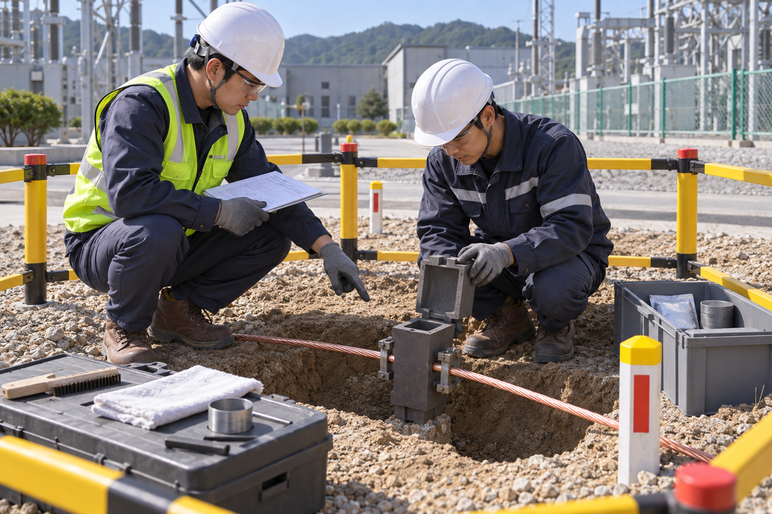
This illustration provides educational context. It is not an actual incident photograph or evidence of equipment suitability; any AI-generated depiction is illustrative only.
The scenario and record comparisons are fictional teaching examples, not records of real incidents, measurements, inspections, signatures or approvals.
| Stage | Fictional situation |
|---|---|
| Initial situation | A fictional crew prepares an exothermic ground connection. |
| Changed condition | Condensation is observed inside a mold previously dried earlier in the day. |
| Failure path | The earlier record and dry exterior are treated as current proof. |
| Possible outcome | Contact between moisture and hot material could cause spatter, burns or a defective joint. |
| Prevention barrier | Hold activation; identify the present condition and whether material was already added, then obtain the exact manufacturer recovery procedure. |
Failure mechanisms
Prior drying and a dry exterior do not establish the current condition inside a mold or conductor. Moisture can return after storage or exposure. Distinguish preparation before material placement from a fault after material has been added; do not improvise heating, water addition or re-ignition.
A low measured grounding resistance does not prove every connection is sound. Joint compatibility, visual acceptance and conductor damage checks serve a different purpose from the system test. Record test arrangement, circuit state, parallel paths and applicable acceptance basis.
Burial hides the joint. Complete the required joint inspection, location and photographs before covering it, then follow the accepted sequence for backfill and final tests. This does not imply all grounding tests must occur before backfill.
Work sequence: Review design and utilities → Prepare hot-work area → Excavate and place → Check mold combination → Control heat cycle → Inspect before burial → Hold and rework → Test and hand over. This is a teaching flow, not a device drawing or a complete operating procedure.
5. Conditional decisions and common errors
| Situation | Required action | Evidence | Proceed when |
|---|---|---|---|
| Utility position unknown | Hold excavation or driving | Survey and safe-location evidence | Location resolved |
| Moisture observed | Hold activation | Current state and product procedure | Preparation accepted |
| Joint defect found | Do not bury | Joint ID and inspection criteria | Disposition verified |
| System test proposed | Review test boundary | Circuit state and measurement plan | Test authorized |
Similar observations, different decisions
The scenario and record comparisons are fictional teaching examples, not records of real incidents, measurements, inspections, signatures or approvals.
| Observation | Insufficient conclusion | Required distinction |
|---|---|---|
| Dried earlier | Past preparation | Current moisture may differ |
| Low resistance | System measurement | Not individual-joint proof |
| Backfill complete | Joint covered | Inspection cannot be assumed |
6. Roles and responsibilities
| Role | Responsibility |
|---|---|
| Work supervisor | Confirm utility evidence and the task scope, resources, interfaces and stop authority. |
| Qualified technical reviewer | Review combustible zone, model limits, compatibility and unresolved technical conditions within assigned competence. |
| Work crew | Apply the listed controls, report changes and stop when evidence or safeguards are missing. |
| Inspector / assessor | Record actual worker position and other relevant checks; do not mark unverified conditions as accepted. |
| Handover authority | Reconcile photos and location, restrictions and outstanding actions before the next task. Role labels do not establish a legal credential. |
Supervision and handover focus
| Stage | Management action | Evidence |
|---|---|---|
| Review design and utilities | 1. Record utility evidence2. Record excavation and rod points3. Record operating ground state | 1. Utility evidence2. Excavation and rod points3. Operating ground state |
| Prepare hot-work area | 1. Record combustible zone2. Record material and sds3. Record worker and ventilation | 1. Combustible zone2. Material and SDS3. Worker and ventilation |
| Check mold combination | 1. Record dryness evidence2. Record mold and conductor id3. Record closure and clamp | 1. Dryness evidence2. Mold and conductor ID3. Closure and clamp |
| Control heat cycle | 1. Record worker position2. Record fire watch conditions3. Record air and wind | 1. Worker position2. Fire watch conditions3. Air and wind |
| Hold and rework | 1. Record current material state2. Record joint hold identity3. Record isolation and impact | 1. Current material state2. Joint hold identity3. Isolation and impact |
| Test and hand over | 1. Record photos and location2. Record measurement arrangement3. Record backfill and test stages | 1. Photos and location2. Measurement arrangement3. Backfill and test stages |
7. Hold points and record comparison
| Hold point | Evidence before release | Actual approval |
|---|---|---|
| HP-0 Scope | Utility investigation, grounding electrode/conductor placement, approved exothermic connection, cooling, joint inspection, pre-burial records, planned backfill and grounding-system tests. | |
| HP-1 Prepare hot-work area | Combustible zone; Material and SDS; Worker and ventilation; Alarm and fire response | |
| HP-2 Check mold combination | Dryness evidence; Mold and conductor ID; Closure and clamp; Material condition | |
| HP-3 Hold and rework | Current material state; Joint hold identity; Isolation and impact; Cause and reinspection | |
| HP-4 Test and hand over | Photos and location; Measurement arrangement; Backfill and test stages; Criteria and recipient |
Hold points are internal project checks. They are not universal statutory permits and do not grant work permission. Reassess after defects, changed conditions and shift changes.
Record comparison
The scenario and record comparisons are fictional teaching examples, not records of real incidents, measurements, inspections, signatures or approvals.
The boxes are static record prompts, not interactive or saved approvals. A tick does not establish suitability or permission to restart. Record the evidence, person, time and unresolved issues; retain the change history.
| Record | Insufficient record | Record checklist |
|---|---|---|
| Review design and utilities | Only marked “OK” | □ Utility evidence□ Excavation and rod points□ Operating ground state□ Drawing and joint ID |
| Check mold combination | Only marked “OK” | □ Dryness evidence□ Mold and conductor ID□ Closure and clamp□ Material condition |
| Hold and rework | Only marked “OK” | □ Current material state□ Joint hold identity□ Isolation and impact□ Cause and reinspection |
| Test and hand over | Only marked “OK” | □ Photos and location□ Measurement arrangement□ Backfill and test stages□ Criteria and recipient |
8. Site checklist and emergency response
| Site check | Actual result | Person / action |
|---|---|---|
| Review design and utilities: Utility evidence; Excavation and rod points; Operating ground state; Drawing and joint ID | ||
| Prepare hot-work area: Combustible zone; Material and SDS; Worker and ventilation; Alarm and fire response | ||
| Excavate and place: Location verification; Exposed installations; Ground and access; Electrode position | ||
| Check mold combination: Dryness evidence; Mold and conductor ID; Closure and clamp; Material condition | ||
| Control heat cycle: Worker position; Fire watch conditions; Air and wind; Cooling and opening | ||
| Inspect before burial: Joint acceptance; Conductor condition; Pre-burial record; Test stage and boundary | ||
| Hold and rework: Current material state; Joint hold identity; Isolation and impact; Cause and reinspection | ||
| Test and hand over: Photos and location; Measurement arrangement; Backfill and test stages; Criteria and recipient |
Stop work
Stop excavation or rod driving for unknown utilities or unstable ground. Hold activation for moisture, contamination, mismatched components, poor mold closure or missing fire controls. Keep defective joints exposed and identified until disposition.
Emergency response
Clear the hot-material and utility hazard area, activate site emergency response and obtain medical help for burns or electrical contact. Do not add water to reacting material or attempt improvised recovery. Qualified personnel establish the safe state and product-specific response.
9. Sources and review limits
Public-source access/review: 2026-10-13.
| Official source | Reviewed scope and limits |
|---|---|
| OSHA 1926.651 | Utility investigation and safe location as excavation approaches installations; other excavation safeguards remain applicable. |
| nVent ERICO installation and inspection guidance | Manufacturer reference for compatible components and moisture/contamination hazards; verify actual product instructions and US installation requirements. |
No actual equipment model, SDS, site measurements, design calculations or authorization record was supplied. Product-specific limits and methods must be verified before use. Federal OSHA is a baseline within its scope; determine the applicable State Plan and local requirements. Manufacturer guidance is not government approval; an incorporated standard differs from voluntary guidance. No nationwide-compliance or expert-approval claim is made.
10. PDF guidance and FAQ
PDF A covers basic task controls; B focuses on technical failures; C covers supervision, records and handover. The article has eight stages with four items per main cell; each PDF has six key stages with three items per main cell. P/S/R/A, measurements, confirmations and signatures remain blank for actual site assessment.
PDFs are complementary six-stage extracts. Apply all eight body stages and the actual equipment/site procedure.
Can a loaded damp mold be heated as a quick fix?
Do not improvise. Keep the area controlled and follow the manufacturer procedure for the actual loaded condition.
Is one resistance limit valid for every ground system?
No. Use the applicable design/code requirements and measurement conditions for that system.
May an operating ground be disconnected for a test?
Only through a separately authorized electrical method that controls the consequences; this worksheet does not permit it.
Has a professional verified or approved this document?
No. Public sources and editorial, layout and consistency checks were reviewed using AI. No site inspection or professional technical approval has been performed. Obtain appropriate professional review before use.
11. Revision history and authorship
This is reference content written and revised with AI. It has not been verified or approved by a professional. Review by a suitably qualified professional and site authorization are required before use.
| Date | Version | Change | Review status |
|---|---|---|---|
| 2026-10-13 | US 1.0 | New US edition from assigned Korean source; task decisions, records and PDFs localized. | AI editorial review; no professional technical approval |
Korean edition revision history: 2026-09-20 (v1.0): initial article, sources, fictional analysis and PDF editorial checks; 2026-09-23 (v1.1): task decisions, record checklist, JSA and three PDF variants revised. These are editorial records, not professional technical approval. US v1.0 adapts the earlier edition to United States requirements and terminology.
Site reviewers must add their actual qualifications, scope, date and approval only after the review occurs.