A girder's strong-axis bending capacity does not establish stability during transport, lifting or temporary support. Identify lift points, center of gravity and each changing support condition.
This reference material was written and revised with AI. It has not been verified or approved by a professional. Review by a suitably qualified professional and required site approval are necessary before field use.
Stop before proceeding
Stop if radius changes, lift point damaged, bracing incomplete. Keep the affected operation on hold until the listed evidence and proceed conditions are satisfied; a low risk score does not release missing safeguards.
1. Legal and technical scope
Apply construction crane Subpart CC to the actual crane operation and 1926.1432 when multiple cranes support the load. Use 1926.704 precast support and lifting provisions where applicable; steel-erection rules are not transferred wholesale to concrete girders. The FHWA 2015 reference catalog confirms staged stability scope; full PDF retrieval failed in this review, so no claim of fresh full-manual or design-calculation verification is made.
Confirm whether federal OSHA or an OSHA-approved State Plan covers this employer and worksite; state requirements and public-sector coverage can differ. Apply the task-specific provisions and limitations identified above.
| Basis | Application |
|---|---|
| OSHA 29 CFR 1926.704 | Precast support against collapse, lifting attachments and exposure below members. |
| OSHA 29 CFR 1926.1432 | Qualified multiple-crane plan, appropriate engineering and lift-direction briefing. |
| FHWA NHI-15-044 catalog | Official catalog reviewed; construction-stage stability reference, not project design acceptance. Full PDF retrieval failed. |
| OSHA State Plans | Official overview of federal and State Plan jurisdiction and differing public-sector coverage, checked 2026-10-13. Individual state rules require a site-specific check. |
2. Scope and required inputs
Included scope
Receive, support, lift and place precast or prestressed concrete girders, verify bearing and lateral restraint, then transfer documented restrictions to subsequent work.
Separate assessment
Steel girders, segmental launching, marine crane operations, changed lifting points and damaged-member acceptance require separate engineered plans.
| Input | Evidence needed |
|---|---|
| Plan member and lift | Member and lifting points; Stage stability; Crane radii and shares; Traffic and services. |
| Set crane and rigging | Ground and setup; Rigging and inserts; Clearance plan; Crane configuration. |
| Place on bearings | Seat and contact; Girder inclination; Hands and exclusion; Temporary restraint. |
| Handoff stages | Brace retention; Connections and deck plan; Final survey; Receiving authority. |
No site measurements, equipment manuals for the actual installation, inspection records or signed technical approvals were supplied. Confirm the applicable requirements and actual product instructions before use; record each criterion with its units, source and equipment or work-area ID.
3. Eight-stage JSA
| Job stage | Hazards and effects | Failure factors | Technical and procedural controls | Site verification | P | S | R | A |
|---|---|---|---|---|---|---|---|---|
| 1. Plan member and lift | 1. Girder overturns2. Crane overload3. Wrong member4. Uncontrolled public exposure | 1. Center unknown2. Loads assumed equal3. ID mismatch4. Road interface open | 1. Verify erection design2. Check each crane load3. Match member records4. Plan exclusion and closure | 1. Member and lifting points2. Stage stability3. Crane radii and shares4. Traffic and services | ||||
| 2. Receive and support | 1. Girder rolls2. Trailer shifts3. Bearing damage4. Person trapped | 1. Wrong support location2. Restraints released early3. Dunnage unsuitable4. Hands in support | 1. Use designed supports2. Sequence restraint release3. Inspect member condition4. Keep people clear | 1. Transport supports2. Member condition3. Restraints and route4. Receiving release | ||||
| 3. Set crane and rigging | 1. Crane overturns2. Rigging failure3. Power contact4. Dropped gear | 1. Ground unverified2. Wrong angles3. Envelope unchecked4. Hardware damaged | 1. Verify support reactions2. Use designed rigging3. Control overhead hazards4. Inspect rated gear | 1. Ground and setup2. Rigging and inserts3. Clearance plan4. Crane configuration | ||||
| 4. Trial and lift | 1. Unequal load2. Girder twists3. Collision4. Signal loss | 1. Motion uncoordinated2. Lift point wrong3. Path obstructed4. Multiple commands | 1. Brief lift director plan2. Check trial response3. Clear complete path4. Use agreed signals | 1. Trial balance2. Crane responses3. Lift route4. Communication | ||||
| 5. Place on bearings | 1. Finger crush2. Girder rotation3. Bearing displacement4. Edge fall | 1. Hand alignment2. Lateral restraint absent3. Wrong seat4. Unsafe access | 1. Use alignment tools2. Retain planned support3. Verify bearing position4. Provide protected access | 1. Seat and contact2. Girder inclination3. Hands and exclusion4. Temporary restraint | ||||
| 6. Brace and release | 1. Girder overturns2. Anchor failure3. Sudden load shift4. Adjacent impact | 1. Brace incomplete2. Weak anchor3. Ropes slackened early4. Wind unassessed | 1. Verify entire brace path2. Inspect connections3. Transfer load by plan4. Maintain weather controls | 1. Brace strength and stiffness2. Anchor and fasteners3. Release sequence4. Post-release stability | ||||
| 7. Review abnormality | 1. Progressive instability2. Damaged member used3. Unsafe recovery4. Crane overload | 1. Movement dismissed2. Crack unmarked3. Improvised correction4. Radius altered | 1. Stop affected sequence2. Exclude collapse area3. Obtain engineered recovery4. Reassess equipment loads | 1. Observed movement2. Member damage3. Support and crane state4. Recovery authorization | ||||
| 8. Handoff stages | 1. Early brace removal2. Deck overload3. Loose hardware4. Restrictions lost | 1. Next girder assumed enough2. Loads unreviewed3. Debris retained4. Records absent | 1. Retain required bracing2. Review subsequent loads3. Clear loose items4. Transfer stage restrictions | 1. Brace retention2. Connections and deck plan3. Final survey4. Receiving authority |
P = likelihood; S = severity; R = risk under the site method; A = the site-defined acceptance/authorization decision. Complete only after actual assessment. Blank cells and checklist prompts are not completed inspections.
4. Fictional scenario and failure mechanisms
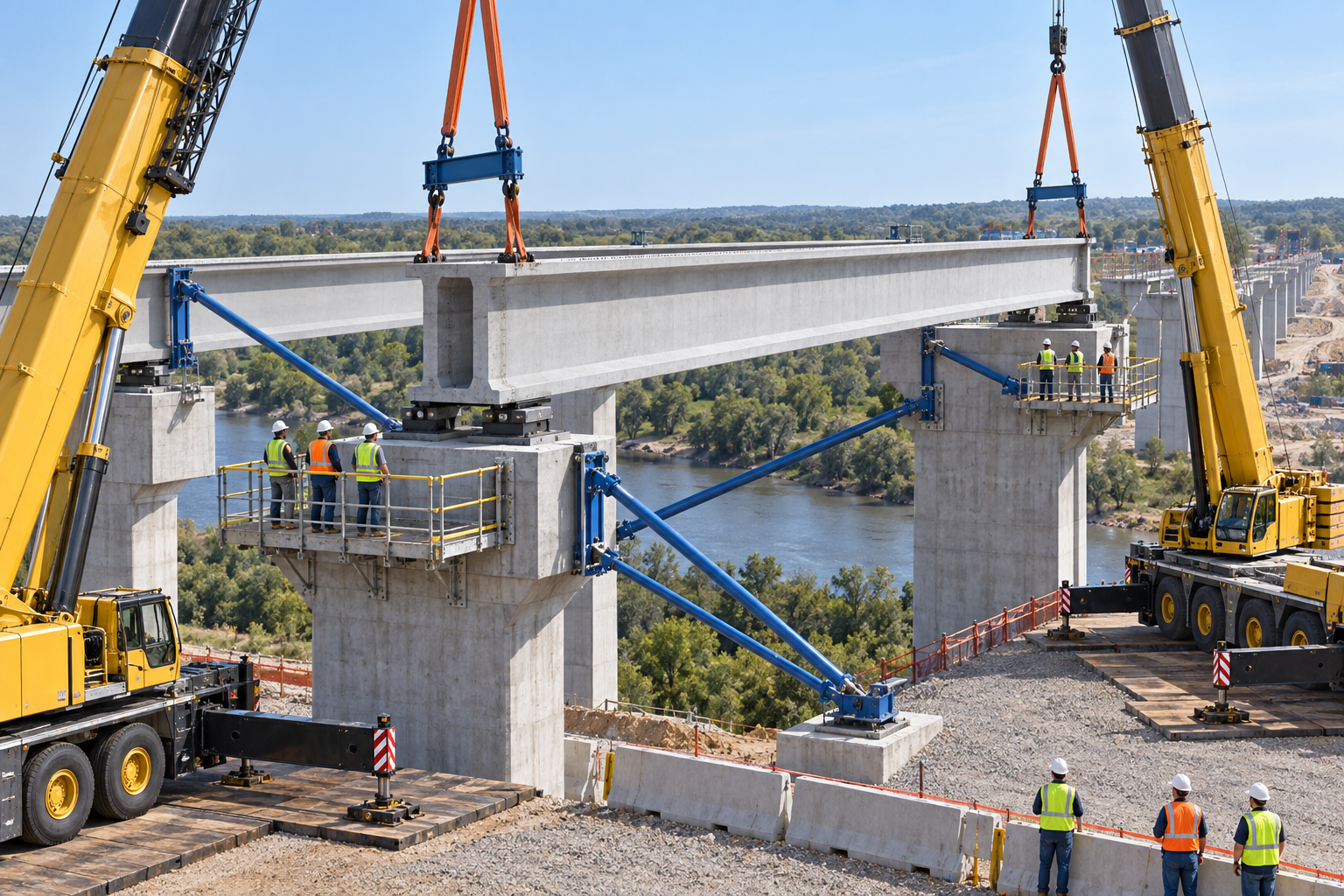
Retained AI-generated educational illustration from the source edition; not a real incident photograph, approved installation drawing or evidence of equipment suitability.
The scenario and record comparisons are fictional teaching examples, not records of real incidents, measurements, inspections, signatures or approvals.
| Item | Fictional scenario |
|---|---|
| Initial | Two cranes place a long concrete girder on bearings. |
| Change | The crew wants to slacken ropes before lateral braces are complete. |
| Failure | Vertical seating is mistaken for complete stability. |
| Outcome | Wind or eccentricity can rotate the girder or displace a bearing. |
| Barrier | Retain planned support until bearing contact, lateral braces and their anchorages meet the release criteria. |
Why the controls matter
A girder's strong-axis bending capacity does not establish stability during transport, lifting or temporary support. Identify lift points, center of gravity and each changing support condition.
Do not add crane nameplate capacities or assume equal sharing. Assess each crane at its actual radius, rigging geometry, movement and share of load throughout the lift.
Bearing contact establishes a vertical load path; lateral restraint also needs adequate strength, stiffness and anchorage. Arrival of the next girder does not authorize removing a brace. Recheck staged loads as diaphragms and deck construction change the system.
Decision sequence
| Step | Decision |
|---|---|
| Known | The crew wants to slacken ropes before lateral braces are complete. |
| Unknown | Actual condition, extent of damage and suitability of seat and contact, girder inclination remain to be established. |
| Hold | Vertical seating is mistaken for complete stability. |
| Evidence | Link seat and contact, girder inclination, hands and exclusion, temporary restraint, observed movement, member damage to the affected equipment or work area. |
| Next | Retain planned support until bearing contact, lateral braces and their anchorages meet the release criteria. |
5. Conditional decisions and common errors
| Condition | Action | Evidence | Proceed when |
|---|---|---|---|
| Radius changes | Hold movement | Each crane load case | Revised lift accepted |
| Lift point damaged | Quarantine member | ID and damage review | Use disposition issued |
| Bracing incomplete | Hold rope release | Bearing brace and anchor checks | Lateral stability verified |
| Next-stage load changes | Review temporary state | Connection and deck sequence | Stage loads accepted |
Similar appearance, different evidence
The scenario and record comparisons are fictional teaching examples, not records of real incidents, measurements, inspections, signatures or approvals.
| Comparison | Supported decision | Insufficient basis |
|---|---|---|
| Condition | Each crane load case | Radius changes has not been resolved. |
| Evidence | Bearing brace and anchor checks | A photograph or a completed-looking task without the relevant inspection record. |
| Release | Stage loads accepted | Completion of one step does not release the excluded tasks in section 2. |
6. Roles and responsibilities
| Role | Responsibility |
|---|---|
| Work supervisor | Assign the task boundary, stop authority, interfaces and emergency communication for precast concrete bridge girder lifting and erection. |
| Technical lead | Confirm Member and lifting points; Stage stability; Crane radii and shares; Traffic and services. Resolve design and manufacturer limits before work. |
| Authorized crew | Apply Ground and setup; Rigging and inserts; Clearance plan; Crane configuration. Stop when the working arrangement changes. |
| Inspector / receiving lead | Review Seat and contact; Girder inclination; Hands and exclusion; Temporary restraint. Transfer Brace retention; Connections and deck plan; Final survey; Receiving authority. |
Role labels allocate responsibilities; they do not confer a legal qualification. Verify the competence, training and authority required for the actual task.
Record and handoff perspective
| Stage | Record controls | Verification |
|---|---|---|
| Plan member and lift | 1. Record member and lifting points2. Record stage stability3. Record crane radii and shares | 1. Stage stability2. Crane radii and shares3. Traffic and services |
| Set crane and rigging | 1. Record ground and setup2. Record rigging and inserts3. Record clearance plan | 1. Rigging and inserts2. Clearance plan3. Crane configuration |
| Trial and lift | 1. Record trial balance2. Record crane responses3. Record lift route | 1. Crane responses2. Lift route3. Communication |
| Place on bearings | 1. Record seat and contact2. Record girder inclination3. Record hands and exclusion | 1. Girder inclination2. Hands and exclusion3. Temporary restraint |
| Review abnormality | 1. Record observed movement2. Record member damage3. Record support and crane state | 1. Member damage2. Support and crane state3. Recovery authorization |
| Handoff stages | 1. Record brace retention2. Record connections and deck plan3. Record final survey | 1. Connections and deck plan2. Final survey3. Receiving authority |
7. Hold points and record comparison
| Hold point | Evidence before release | Actual record |
|---|---|---|
| HP-0 Start | Receive, support, lift and place precast or prestressed concrete girders, verify bearing and lateral restraint, then transfer documented restrictions to subsequent work. | |
| HP-1 Plan member and lift | Member and lifting points; Stage stability; Crane radii and shares; Traffic and services | |
| HP-2 Set crane and rigging | Ground and setup; Rigging and inserts; Clearance plan; Crane configuration | |
| HP-3 Brace and release | Brace strength and stiffness; Anchor and fasteners; Release sequence; Post-release stability | |
| HP-4 Handoff stages | Brace retention; Connections and deck plan; Final survey; Receiving authority |
These are internal hold points, not issued permits. Recheck affected points after a change, fault or shift handoff; link the actual approval record.
Record comparison
The scenario and record comparisons are fictional teaching examples, not records of real incidents, measurements, inspections, signatures or approvals.
The boxes are static record prompts, not interactive or saved approvals. A tick does not establish suitability or permission to restart. Record the evidence, person, time and unresolved issues; retain the change history.
| Record | Insufficient | Record checklist |
|---|---|---|
| Plan member and lift | "Checked" without target, criteria or result | □ Member and lifting points□ Stage stability□ Crane radii and shares□ Traffic and services |
| Set crane and rigging | "Checked" without target, criteria or result | □ Ground and setup□ Rigging and inserts□ Clearance plan□ Crane configuration |
| Place on bearings | "Checked" without target, criteria or result | □ Seat and contact□ Girder inclination□ Hands and exclusion□ Temporary restraint |
| Handoff stages | "Checked" without target, criteria or result | □ Brace retention□ Connections and deck plan□ Final survey□ Receiving authority |
8. Site checklist and emergency response
| Check | Result | Person / action |
|---|---|---|
| □ Plan member and lift: Member and lifting points | ||
| □ Receive and support: Transport supports | ||
| □ Set crane and rigging: Ground and setup | ||
| □ Trial and lift: Trial balance | ||
| □ Place on bearings: Seat and contact | ||
| □ Brace and release: Brace strength and stiffness | ||
| □ Review abnormality: Observed movement | ||
| □ Handoff stages: Brace retention | ||
| □ Emergency access and handoff restrictions |
Stop work
Stop if radius changes, lift point damaged, bracing incomplete. Keep the affected operation on hold until the listed evidence and proceed conditions are satisfied; a low risk score does not release missing safeguards.
Emergency response
Stop coordinated movement from safe positions and keep people outside the possible collapse area. Do not slacken, pull or reposition an unstable girder by trial. Use the approved stage-specific holding and engineered recovery plan; call site emergency responders and 911 for immediate danger or injury.
9. Sources and review limits
Public-source review: 2026-10-14. Official regulation pages and specific technical references are distinguished below; no agency or manufacturer has approved this content.
| Source | Reviewed scope and limitation |
|---|---|
| OSHA 29 CFR 1926.704 | Precast support against collapse, lifting attachments and exposure below members. |
| OSHA 29 CFR 1926.1432 | Qualified multiple-crane plan, appropriate engineering and lift-direction briefing. |
| FHWA NHI-15-044 catalog | Official catalog reviewed; construction-stage stability reference, not project design acceptance. Full PDF retrieval failed. |
| OSHA State Plans | Official overview of federal and State Plan jurisdiction and differing public-sector coverage, checked 2026-10-13. Individual state rules require a site-specific check. |
No site measurements, equipment manuals for the actual installation, inspection records or signed technical approvals were supplied. Confirm the applicable requirements and actual product instructions before use; record each criterion with its units, source and equipment or work-area ID.
10. PDF guidance and FAQ
PDF A covers basic task controls; B focuses on technical failures; C covers supervision, records and handover. The article has eight stages with four items per main cell; each PDF has six key stages with three items per main cell. P/S/R/A, measurements, confirmations and signatures remain blank for actual site assessment.
Content group
jsa-girder-erection
Can two crane capacities be added?
No. Check each crane and changing load distribution.
Does contact with bearings permit release?
Only with the required lateral stability and approved release sequence.
Can a damaged lifting point be relocated?
Not without the required member and lifting-design review.
Does the next girder allow brace removal?
Only when the designed stage and release conditions are met.
Has a professional approved this JSA?
This reference material was written and revised with AI. It has not been verified or approved by a professional. Review by a suitably qualified professional and required site approval are necessary before field use.
11. Revision history and authorship
This reference material was written and revised with AI. It has not been verified or approved by a professional. Review by a suitably qualified professional and required site approval are necessary before field use.
Korean source created 2026-09-19. This US edition adapts the Korean source; earlier editorial revisions do not constitute professional approval of this edition.
| Date | Edition | Change | Review status |
|---|---|---|---|
| 2026-09-19 | Korean source v1.1 | Source editorial publication or revision; retained as provenance of the Korean edition. | Editorial record only; no professional approval of this US edition. |
| 2026-09-26 | Korean source v1.2 | Source editorial publication or revision; retained as provenance of the Korean edition. | Editorial record only; no professional approval of this US edition. |
| 2026-10-14 | 1.0 | US localization: preserve task judgments; replace Korean legal applicability with scoped US references. | AI editorial and output checks; no professional technical approval. |