Positioning and securing a packaged generator, controlling starting and electrical sources, installing separately supported exhaust and cooling-air connections, and handing installation evidence to a separately authorized commissioning team.
Hold for uncertain automatic-start or electrical isolation, forced exhaust alignment, incomplete support, an unreviewed outlet change, fuel leakage, exhaust entry, unexpected motion or abnormal vibration.
Reference content written and revised with AI. It has not been verified or approved by a professional. Review by a suitably qualified professional and site approval are required before use.
1. Legal and technical scope
For construction installation, apply the relevant OSHA Part 1926 requirements, including 1926.251 for rigging, 1926.417 for deenergized circuits and 1926.55 for applicable airborne contaminants. General-industry servicing has its own energy-control and electrical framework. Building, fire, electrical and emissions approvals depend on the actual jurisdiction and installation; no blanket national installation approval is claimed.
Determine Federal OSHA or the applicable OSHA-approved State Plan, including public/private employer coverage. State Plans must be at least as effective and can impose different or additional requirements. The actual activity determines construction versus general-industry scope. Manufacturer instructions, consensus standards, project design and site approvals have distinct roles; this page is not a finding of nationwide compliance.
| Basis | Application and limits |
|---|---|
| OSHA 1926.251 | Rigging identification, capacity and inspection in construction. |
| OSHA 1926.417 | Circuit deactivation, rendering inoperative and tagging; not the complete electrical installation code. |
| OSHA 1926.55 | Air-contaminant assessment and control within construction scope. |
| Cummins T-030, Issue 9, February 2015 | Selected section 6.2 exhaust guidance and backpressure example. Independent supports, expansion and discharge considerations; example dimensions and calculations are not site limits. |
2. Scope and required inputs
Included: Positioning and securing a packaged generator, controlling starting and electrical sources, installing separately supported exhaust and cooling-air connections, and handing installation evidence to a separately authorized commissioning team.
Separate review: Utility paralleling, protection bypass, live exhaust adjustment, actual load-bank or automatic-transfer testing and fuel-system commissioning require their own approved procedures.
| Input | Required evidence |
|---|---|
| Review layout | Package and support design; Intakes and nearby occupancy; Cooling route requirements; Fuel and fire boundaries |
| Isolate starting | Starting signal boundary; Battery isolation and covers; Utility output auxiliary feeds; Electrical and motion checks |
| Connect exhaust | Support and nozzle forces; Flexible joint and guides; Route and backpressure basis; Joint and leakage inspection |
| Handover for tests | Exhaust support and routing; Inspection and defect status; Planned test modes and owner; Permitted next-stage release |
Obtain package lifting data, foundation and mount requirements, engine backpressure limits, actual exhaust routing, support and expansion details, cooling-air requirements and outlet-location review. Select lifting, access, eye and hand protection for the actual work. No example pipe diameter, clearance or backpressure value is adopted as a universal limit.
3. Eight-stage JSA
P = likelihood; S = severity; R = risk under the site method; A = acceptance or authorization as defined by the site. Leave these blank until actual assessment and control verification. A low score does not override a legal requirement, product limit or unreleased hold point.
| Job stage | Hazards and effects | Failure factors | Required controls | Site verification | P | S | R | A |
|---|---|---|---|---|---|---|---|---|
| 1. Review layout | 1. Foundation failure2. Exhaust re-entry3. Cooling overheating4. Fuel fire | 1. Package load unknown2. Outlet near intake3. Air route unreviewed4. Fuel interface ignored | 1. Check package and foundation2. Review discharge location3. Separate cooling air path4. Define fuel and fire scope | 1. Package and support design2. Intakes and nearby occupancy3. Cooling route requirements4. Fuel and fire boundaries | ||||
| 2. Position package | 1. Package overturn2. Rigging failure3. Pinched hands4. Mount damage | 1. Engine-only eye used2. Capacity angle unknown3. Hands align bolt holes4. Wrong support location | 1. Use package lifting points2. Verify rigging configuration3. Align with suitable tools4. Check mounts and anchors | 1. Lifted mass and points2. Balance and rigging capacity3. People clear of pinch zones4. Mount and anchor condition | ||||
| 3. Isolate starting | 1. Automatic cranking2. Battery short circuit3. Electrical backfeed4. Residual rotation | 1. Remote start overlooked2. Battery terminals exposed3. Power and control confused4. Stop not verified | 1. Control remote and ATS starts2. Isolate battery by procedure3. Isolate all power sources4. Verify safe access state | 1. Starting signal boundary2. Battery isolation and covers3. Utility output auxiliary feeds4. Electrical and motion checks | ||||
| 4. Install supports | 1. Falling duct section2. Access fall3. Hot-work fire4. Hidden-service damage | 1. Independent support absent2. Unsafe platform3. Fire controls missing4. Drilling location unchecked | 1. Install designed supports2. Provide protected access3. Control approved hot work4. Survey attachment locations | 1. Support and anchor design2. Access and exclusion below3. Hot-work release if needed4. Substrate and service checks | ||||
| 5. Connect exhaust | 1. Engine outlet damage2. Restrained expansion3. High backpressure4. Exhaust leakage | 1. Flanges forced together2. Flexible section misused3. Route changed without review4. Joint assembly defective | 1. Align before connecting2. Allow designed movement3. Review installed flow path4. Verify specified joints | 1. Support and nozzle forces2. Flexible joint and guides3. Route and backpressure basis4. Joint and leakage inspection | ||||
| 6. Inspect discharge | 1. Hot-surface burn2. Adjacent ignition3. Occupied-space exposure4. Condensate backflow | 1. Heat protection absent2. Clearance not checked3. Outlet moved toward intake4. Drain arrangement wrong | 1. Guard hot surfaces2. Verify fire and heat details3. Review discharge re-entry4. Check condensate handling | 1. Shields and insulation2. Penetrations and clearances3. Intakes windows and routes4. Drain and discharge detail | ||||
| 7. Hold and rework | 1. Unexpected restart2. Residual-heat burn3. Fuel ignition4. Unsupported pipe drop | 1. Isolation removed early2. Temperature assumed safe3. Leak not controlled4. Connection opened unsupported | 1. Reconfirm isolation2. Check safe contact state3. Control fuel and ignition4. Support before disconnection | 1. Start and power controls2. Residual heat condition3. Leak and ignition status4. Support and removal sequence | ||||
| 8. Handover for tests | 1. Exhaust exposure2. Defective-system operation3. Unplanned auto transfer4. People left in area | 1. Test plan absent2. Open defects omitted3. ATS restoration uncontrolled4. Area clearance incomplete | 1. Transfer installed evidence2. Record unresolved limits3. Separate test authorization4. Confirm personnel clearance | 1. Exhaust support and routing2. Inspection and defect status3. Planned test modes and owner4. Permitted next-stage release |
4. Hypothetical scenario and failure mechanisms
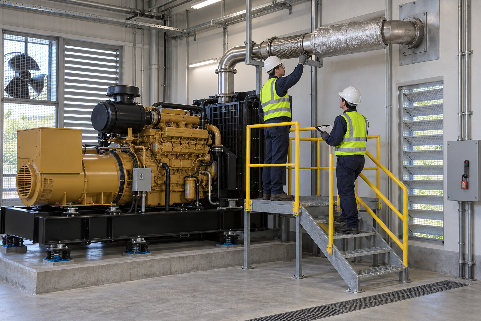 Retained source illustration: an AI-generated educational concept, not a real incident photograph or evidence of equipment suitability.
The following scenario, comparisons and example records are hypothetical teaching material. They do not reproduce actual incidents, measurements, signatures or approvals.
| Item | Hypothetical situation |
|---|---|
| Initial state | The mechanical exhaust connection of a generator is complete. |
| Change | An obstruction led the crew to relocate the exhaust outlet toward a building intake. |
| Failure path | Only the original backpressure calculation remains; the new routing and re-entry conditions were not reviewed. |
| Possible harm | Exhaust may enter occupied space or hot air may recirculate during later operation. |
| Barrier | Hold testing, review the changed exhaust and cooling paths separately, confirm supports and thermal movement, and revise monitored test conditions before release. |
Engine exhaust removes combustion products; radiator discharge carries cooling air. A satisfactory exhaust restriction calculation does not demonstrate that either stream disperses without returning to an intake. Review nearby windows, air intakes, occupied routes and adjacent buildings against the actual layout.
Exhaust pipe and silencer weight belongs on designed supports. A flexible section accommodates permitted movement; it does not support the pipe or correct forced misalignment. Keep installation tolerances and thermal expansion from loading the engine connection.
A stopped control panel does not isolate an automatic transfer switch start signal, starting battery, utility feed, output circuit or auxiliary supply. Identify each boundary and arrange qualified electrical verification. Include stored rotation, fuel and residual heat before rework.
An installation inspection authorizes only its stated next stage. Record the load, mode and duration of subsequent tests and any untested conditions. A successful no-load observation cannot establish full-load backpressure, ventilation performance or acceptance for automatic operation.
| Decision | Reason and evidence |
|---|---|
| Known facts | An obstruction led the crew to relocate the exhaust outlet toward a building intake. |
| Unresolved | Only the original backpressure calculation remains; the new routing and re-entry conditions were not reviewed. |
| Hold reason | Hold for uncertain automatic-start or electrical isolation, forced exhaust alignment, incomplete support, an unreviewed outlet change, fuel leakage, exhaust entry, unexpected motion or abnormal vibration. |
| Evidence needed | Shields and insulation; Penetrations and clearances; Intakes windows and routes; Drain and discharge detail. |
| Next decision | Hold testing, review the changed exhaust and cooling paths separately, confirm supports and thermal movement, and revise monitored test conditions before release. |
5. Conditional decisions and common errors
| Condition | Action | Evidence | Proceed when |
|---|---|---|---|
| Start boundary unclear | Hold physical work; map and verify every feed. | ATS, battery and power isolation. | Safe access verified. |
| Flanges misaligned | Stop force fitting and correct support geometry. | Alignment and support design. | No imposed connection load. |
| Outlet changed | Hold test release and review changed paths. | As-built layout and re-entry review. | Changed route accepted. |
| Ready for test | Transfer installation evidence and retained holds. | Mode, monitoring and stop plan. | Specific test authorized. |
| Comparison | Situation A | Situation B |
|---|---|---|
| Backpressure reviewed | The calculation matches the installed route; discharge re-entry is separately assessed. | The outlet was moved but the old calculation is reused. |
| Connection complete | Supports, expansion and inspection evidence support controlled test preparation. | Bolts are tight but starting isolation and commissioning remain unresolved. |
6. Roles and responsibilities
| Role | Responsibility |
|---|---|
| Work supervisor | Confirm scope, task sequence, exclusion and stop authority. Coordinate review layout with affected operations. |
| Technical reviewer | Resolve the actual design and equipment limits: Package and support design; Intakes and nearby occupancy; Cooling route requirements; Fuel and fire boundaries. |
| Work crew | Perform isolate starting using the approved procedure; report any mismatch before proceeding. |
| Inspector / assessor | Verify Shields and insulation; Penetrations and clearances; Intakes windows and routes; Drain and discharge detail. Record what was actually checked and what remains unresolved. |
| Release / receiving authority | Confirm Exhaust support and routing; Inspection and defect status; Planned test modes and owner; Permitted next-stage release. Transfer restrictions and the next permitted stage. |
These are responsibility examples, not invented statutory credentials. Meet the actual training, competent-person, qualified-person and licensing requirements for the assigned work. Anyone may raise a hazard and request a stop; only the designated authority may release the affected stage after evidence is reviewed.
7. Hold points and record comparison
| Hold point | Evidence before release | Confirmation / approval |
|---|---|---|
| HP-0 Start | Scope, jurisdiction, equipment identity, responsible people and emergency arrangements. | |
| HP-1 Isolate starting | Starting signal boundary; Battery isolation and covers; Utility output auxiliary feeds; Electrical and motion checks | |
| HP-2 Connect exhaust | Support and nozzle forces; Flexible joint and guides; Route and backpressure basis; Joint and leakage inspection | |
| HP-3 Inspect discharge | Shields and insulation; Penetrations and clearances; Intakes windows and routes; Drain and discharge detail | |
| HP-4 Handover for tests | Exhaust support and routing; Inspection and defect status; Planned test modes and owner; Permitted next-stage release |
Hold points are internal evidence gates. They do not replace statutory permits or actual signatures. Recheck affected gates after a change, abnormal event or shift transfer. The blank record must identify the evidence, person, time, limits and release scope.
| Record | Insufficient record | Record checklist |
|---|---|---|
| Isolation | Generator stopped | □ Starting signal boundary□ Battery isolation and covers□ Utility output auxiliary feeds□ Electrical and motion checks |
| Exhaust | Pipe connected | □ Support and nozzle forces□ Flexible joint and guides□ Route and backpressure basis□ Joint and leakage inspection |
| Discharge | Looks clear | □ Shields and insulation□ Penetrations and clearances□ Intakes windows and routes□ Drain and discharge detail |
| Test handover | Ready to run | □ Exhaust support and routing□ Inspection and defect status□ Planned test modes and owner□ Permitted next-stage release |
The □ boxes are static prompts, not saved or interactive approvals. Each checks one record element. A tick alone does not establish suitability or permission to restart. Link equipment IDs and supporting records; retain unresolved matters and the earlier record when conditions change.
8. Site checklist and emergency response
| Check item | Result | Person / action |
|---|---|---|
| Package and support design | ||
| Lifted mass and points | ||
| Starting signal boundary | ||
| Support and anchor design | ||
| Support and nozzle forces | ||
| Shields and insulation | ||
| Start and power controls | ||
| Exhaust support and routing | ||
| Emergency arrangements and unresolved restrictions communicated |
Stop work: Hold for uncertain automatic-start or electrical isolation, forced exhaust alignment, incomplete support, an unreviewed outlet change, fuel leakage, exhaust entry, unexpected motion or abnormal vibration.
Emergency response: For suspected exhaust exposure, stop the test if safely possible, move to uncontaminated outdoor air and activate emergency response; call 911 for serious symptoms or injury. Do not enter contaminated space for unprotected rescue. Control fuel or fire incidents through the site plan and retain electrical and residual-heat precautions after shutdown.
9. Sources and review limits
Official-source review date: October 13, 2026. The following review is limited to the public provisions or selected manufacturer material identified below. It does not establish that any authority approved this article or the actual installation.
- OSHA 1926.251: Rigging identification, capacity and inspection in construction.
- OSHA 1926.417: Circuit deactivation, rendering inoperative and tagging; not the complete electrical installation code.
- OSHA 1926.55: Air-contaminant assessment and control within construction scope.
- Cummins T-030, Issue 9, February 2015: Selected section 6.2 exhaust guidance and backpressure example. Independent supports, expansion and discharge considerations; example dimensions and calculations are not site limits.
- OSHA State Plans: jurisdiction and coverage overview; identify the actual state program before use.
Paid consensus standards and site-specific calculations, manuals, inspection records and product certificates were not independently obtained or verified unless specifically identified. Korean legal citations remain in the preserved Korean source as source history; they are not represented as US legal duties.
10. PDF guidance and FAQ
PDF A covers basic task controls; B examines technical failures; C focuses on supervision, evidence and handover. Each has six rows and three items per main cell. They are complementary extracts: apply all eight body stages and the applicable site procedure. An omitted stage is not permission to omit its controls. PDF HP-0 through HP-4 are worksheet labels; match the event, evidence and authority rather than assuming they match another permit by number.
P/S/R/A, actual measurements, confirmations and signatures remain blank. The PDFs are uncompleted reference worksheets, not issued work permits.
Content group ID: jsa-generator-installation
Does acceptable backpressure prove safe discharge?
No. Review exhaust re-entry and cooling-air recirculation separately using the actual outlet and intake layout.
Can the flexible section carry the silencer?
No. Provide the designed independent support and correct alignment.
Does an installation check permit automatic operation?
No. Complete the separately authorized commissioning, protection and operating-acceptance steps.
Can exhaust safety be judged by smell?
No. Carbon monoxide is odorless; use the specified exposure assessment and monitoring arrangements.
Has a professional verified or approved this document?
No. This is AI-assisted reference material. Editorial and layout checks are not a physical inspection or professional technical approval. Obtain qualified professional review and required site approval before use.
11. Revision history and authorship
Reference content written and revised with AI. It has not been verified or approved by a professional. Review by a suitably qualified professional and site approval are required before use.
This system has not physically inspected the equipment, structures, ground, atmosphere or worksite. The document does not replace legal advice, manufacturer procedures, engineering design, inspection certificates, qualification evidence, the site risk assessment or an actual work permit.
Before use, a suitably qualified and authorized person must review the actual equipment, loads, methods, protection, inspection and emergency arrangements and resolve open issues. Record the real reviewer, organization, qualifications, delegated authority, reviewed documents, date, signature, exclusions and conditions of approval separately.
| Date | Version | Change | Review status |
|---|---|---|---|
| 2026-09-19 | 1.1 | Korean source revision retained in the source snapshot. | Historical editorial status; not US professional approval. |
| 2026-09-26 | 1.2 | Korean source revision retained in the source snapshot. | Historical editorial status; not US professional approval. |
| 2026-10-13 | US 1.0 | US localization of the assigned Korean source; task reasoning, educational image and history retained; US scope and sources reviewed. | AI-assisted editorial work; professional approval not performed. |