The puller reading does not establish the condition at every bend. Bend radius, cable arrangement and friction affect local forces. Moving one roller can change sidewall pressure and support even when the measured tension remains below its limit.
This is reference content written and revised with AI. It has not been verified or approved by a professional. Review by a suitably qualified professional and site authorization are required before use.
Stop before starting
Stop for tension increase, cable stall, shifted rollers, moving drum/puller support, signal loss or entry into the tension line or inside bend. Hold access and connection release until residual energy and vertical support are verified.
1. Legal and technical scope
| Basis | Scope and limits |
|---|---|
| OSHA 1926.416 | Construction protection from actual electrical hazards. |
| OSHA 1926.300 | Hand/power-tool safeguards within scope. |
| Southwire Power Cable Installation Guide | Manufacturer guidance on route, pulling tension, bend pressure and rollers; actual cable-specific limits required. |
This construction reference uses 1926.416 for electrical exposures, 1926.417 for applicable circuit lockout/tagging and 1926.300 for tool safeguards. Resolve actual equipment and access requirements and State Plan rules. Southwire guidance explains route forces; use the actual cable and pulling-method limits, not a universal tension, bend radius, sidewall-pressure or lubricant value.
2. Scope and required inputs
Included work
Reviewing a new feeder route, setting the drum and puller, checking pulling attachments and rollers, making a controlled trial and continuous pull, securing and sealing ends and handing over inspection records.
Separate assessment
Manhole or confined-space entry, live connection, electrical testing, energization and forced pulling beyond approved limits require separate authorization and methods.
| Required input | Evidence to obtain |
|---|---|
| Review route and forces | Cable and pulling method; Bends length elevation; Drum support basis; Entry and electrical boundary |
| Set drum and puller | Stand and ground; Spindle and braking; Puller anchorage; Exclusion and escape |
| Inspect cable and rollers | Cable identity; Roller rating and layout; Electrical safeguards; Connection compatibility |
| Trial pull and signals | Tension and roller behavior; Drum braking; Hands feet exclusion; Full-route communication |
No actual equipment model, SDS, site measurements, design calculations or authorization record was supplied. Product-specific limits and methods must be verified before use. Federal OSHA is a baseline within its scope; determine the applicable State Plan and local requirements. Manufacturer guidance is not government approval; an incorporated standard differs from voluntary guidance. No nationwide-compliance or expert-approval claim is made.
3. Eight-stage JSA
| Job stage | Hazards and effects | Failure factors | Technical and procedural controls | Site verification | P | S | R | A |
|---|---|---|---|---|---|---|---|---|
| 1. Review route and forces | 1. Cable damage2. Rope failure3. Support collapse4. Entry exposure | 1. Cable limit unknown2. Bends omitted3. Drum weight unknown4. Entry assumed allowed | 1. Verify cable-specific limits2. Review actual route forces3. Confirm drum and floor load4. Separate entry approval | 1. Cable and pulling method2. Bends length elevation3. Drum support basis4. Entry and electrical boundary | ||||
| 2. Set drum and puller | 1. Drum overturn2. Spindle release3. Puller movement4. Person struck | 1. Stand underrated2. Axle unsecured3. Reaction unreviewed4. Route shared | 1. Use rated drum stand2. Secure spindle and brake3. Support puller reaction4. Separate people and line | 1. Stand and ground2. Spindle and braking3. Puller anchorage4. Exclusion and escape | ||||
| 3. Inspect cable and rollers | 1. Jacket damage2. Roller pinch3. Electrical contact4. Pulling-eye release | 1. Wrong reel direction2. Roller spacing poor3. Adjacent source uncontrolled4. Attachment mismatched | 1. Match cable and direction2. Inspect bends and rollers3. Control existing circuits4. Verify eye rope and swivel | 1. Cable identity2. Roller rating and layout3. Electrical safeguards4. Connection compatibility | ||||
| 4. Trial pull and signals | 1. Sudden tension2. Drum overrun3. Hand pinch4. Uncontrolled pull | 1. Start abrupt2. Brake ineffective3. Hands guide cable4. Contact untested | 1. Start by approved trial2. Control drum payout3. Use rollers and guides4. Stop on signal loss | 1. Tension and roller behavior2. Drum braking3. Hands feet exclusion4. Full-route communication | ||||
| 5. Pull and monitor bends | 1. Recoil strike2. Inside-bend crush3. Cable abrasion4. Vertical cable drop | 1. People in line2. Tension unmonitored3. Radius exceeded4. Vertical support missing | 1. Keep force path clear2. Monitor force and progress3. Maintain approved geometry4. Support vertical sections | 1. Recoil and bend boundary2. Tension trend and limits3. Radius and sidewall review4. Vertical support | ||||
| 6. Secure and protect ends | 1. Cable rollback2. Residual-tension release3. Moisture ingress4. Tray overload | 1. Support absent2. Connector released early3. Ends unsealed4. Loads concentrated | 1. Accept fixing before release2. Use controlled release order3. Seal and identify ends4. Review final support loads | 1. Residual energy and sequence2. Fixing arrangement3. End seals and IDs4. Tray and support loads | ||||
| 7. Hold obstruction | 1. Attachment rupture2. Repeated shock loading3. Unexpected restart4. Stored-energy crush | 1. More force applied2. Cause ignored3. Puller not isolated4. Loaded bend entered | 1. Stop abnormal pulling2. Prevent restart3. Support and release safely4. Inspect route and cable | 1. Fault time and tension2. Cable roller condition3. Isolation record4. Residual-load control | ||||
| 8. Inspect and hand over | 1. Damaged cable used2. Wrong termination3. Route trip4. Unauthorized power | 1. History erased2. End IDs differ3. Drum debris left4. Test authority absent | 1. Retain damage assessment2. Match both end IDs3. Clear route and drum area4. Separate later test release | 1. Jacket and tension history2. Circuit end identification3. Sealed ends and route4. Held segments and next work |
P = likelihood; S = severity; R = risk under the site method; A = site-defined acceptance/authorization. These actual assessment cells are blank. A low score never overrides a missing safeguard or a legal or manufacturer restriction.
4. Fictional scenario and failure mechanisms
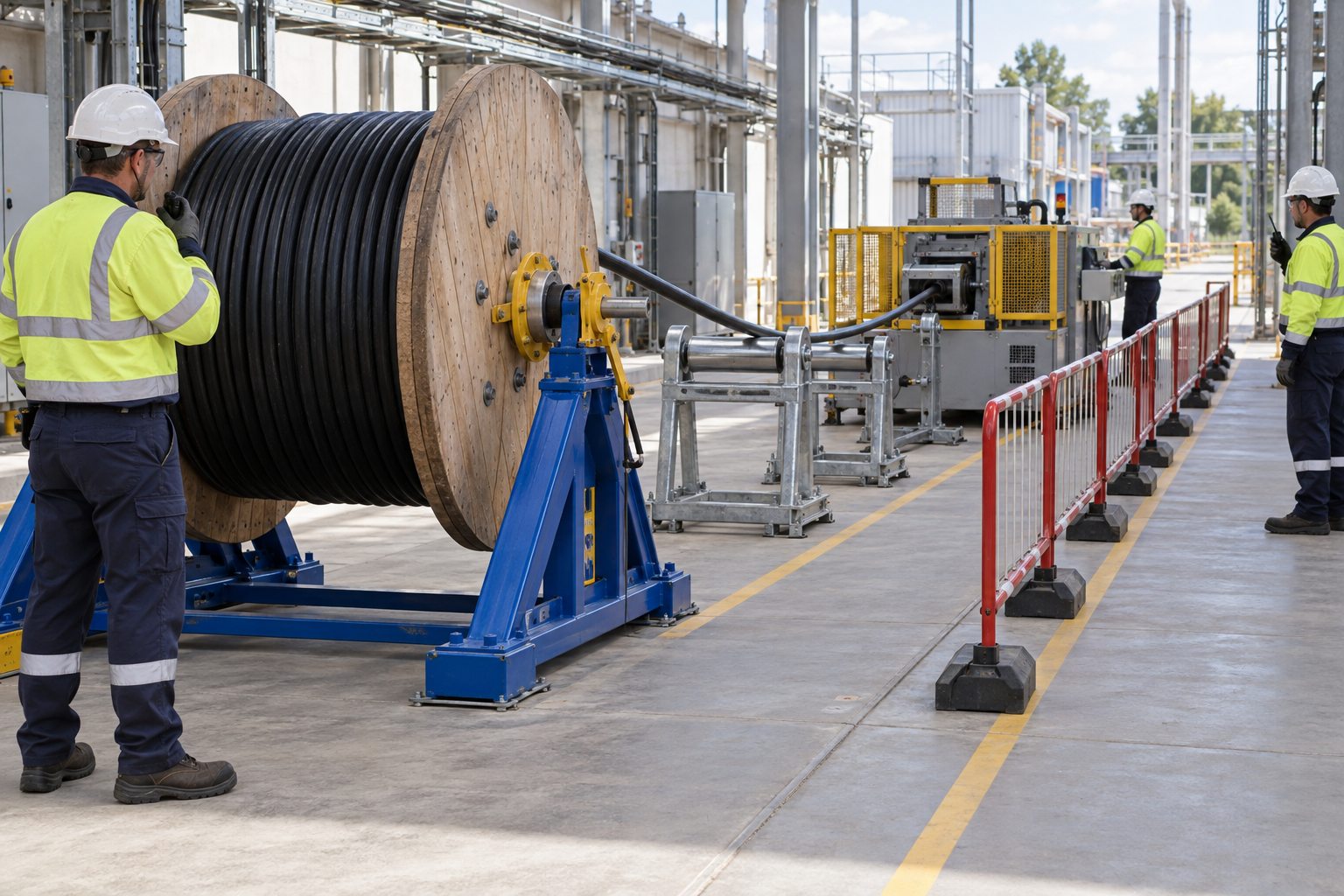
This illustration provides educational context. It is not an actual incident photograph or evidence of equipment suitability; any AI-generated depiction is illustrative only.
The scenario and record comparisons are fictional teaching examples, not records of real incidents, measurements, inspections, signatures or approvals.
| Stage | Fictional situation |
|---|---|
| Initial situation | A fictional feeder pull passes several bends. |
| Changed condition | A roller stops turning freely, cable progress slows and tension rises. |
| Failure path | The crew continues because the displayed value is below the set maximum. |
| Possible outcome | Local damage, connector failure or recoil could develop. |
| Prevention barrier | Stop the pull, prevent restart, support the cable and control residual energy before checking the route and defining the required damage assessment and restart conditions. |
Failure mechanisms
The puller reading does not establish the condition at every bend. Bend radius, cable arrangement and friction affect local forces. Moving one roller can change sidewall pressure and support even when the measured tension remains below its limit.
A stopped puller can leave elastic tension in the rope and cable and gravity load in vertical runs. Before approaching a jam or removing a connector, separately establish restart prevention, access exclusion, cable support and the approved energy-release sequence.
Clearing an obstruction does not establish cable fitness for service. Preserve the time, location and tension trend and assess the affected segment. External appearance or one electrical test cannot prove the absence of every internal or mechanical defect.
Work sequence: Review route and forces → Set drum and puller → Inspect cable and rollers → Trial pull and signals → Pull and monitor bends → Secure and protect ends → Hold obstruction → Inspect and hand over. This is a teaching flow, not a device drawing or a complete operating procedure.
5. Conditional decisions and common errors
| Situation | Required action | Evidence | Proceed when |
|---|---|---|---|
| Tension rises or cable stalls | Stop pulling | Trend, roller and route evidence | Cause corrected |
| Roller moved | Review changed geometry | Bend radius and local force review | Route accepted |
| Puller stopped | Hold access to loaded path | Isolation, support and residual load | Energy controlled |
| Cable reaches destination | Inspect and identify | Damage history and end records | Handover accepted |
Similar observations, different decisions
The scenario and record comparisons are fictional teaching examples, not records of real incidents, measurements, inspections, signatures or approvals.
| Observation | Insufficient conclusion | Required distinction |
|---|---|---|
| Tension below limit | One measured value | Local bend condition separate |
| Puller off | Drive stopped | Stored tension may remain |
| Jacket looks intact | External inspection | Internal condition unproved |
6. Roles and responsibilities
| Role | Responsibility |
|---|---|
| Work supervisor | Confirm cable and pulling method and the task scope, resources, interfaces and stop authority. |
| Qualified technical reviewer | Review stand and ground, model limits, compatibility and unresolved technical conditions within assigned competence. |
| Work crew | Apply the listed controls, report changes and stop when evidence or safeguards are missing. |
| Inspector / assessor | Record actual recoil and bend boundary and other relevant checks; do not mark unverified conditions as accepted. |
| Handover authority | Reconcile jacket and tension history, restrictions and outstanding actions before the next task. Role labels do not establish a legal credential. |
Supervision and handover focus
| Stage | Management action | Evidence |
|---|---|---|
| Review route and forces | 1. Record cable and pulling method2. Record bends length elevation3. Record drum support basis | 1. Cable and pulling method2. Bends length elevation3. Drum support basis |
| Set drum and puller | 1. Record stand and ground2. Record spindle and braking3. Record puller anchorage | 1. Stand and ground2. Spindle and braking3. Puller anchorage |
| Trial pull and signals | 1. Record tension and roller behavior2. Record drum braking3. Record hands feet exclusion | 1. Tension and roller behavior2. Drum braking3. Hands feet exclusion |
| Pull and monitor bends | 1. Record recoil and bend boundary2. Record tension trend and limits3. Record radius and sidewall review | 1. Recoil and bend boundary2. Tension trend and limits3. Radius and sidewall review |
| Hold obstruction | 1. Record fault time and tension2. Record cable roller condition3. Record isolation record | 1. Fault time and tension2. Cable roller condition3. Isolation record |
| Inspect and hand over | 1. Record jacket and tension history2. Record circuit end identification3. Record sealed ends and route | 1. Jacket and tension history2. Circuit end identification3. Sealed ends and route |
7. Hold points and record comparison
| Hold point | Evidence before release | Actual approval |
|---|---|---|
| HP-0 Scope | Reviewing a new feeder route, setting the drum and puller, checking pulling attachments and rollers, making a controlled trial and continuous pull, securing and sealing ends and handing over inspection records. | |
| HP-1 Set drum and puller | Stand and ground; Spindle and braking; Puller anchorage; Exclusion and escape | |
| HP-2 Trial pull and signals | Tension and roller behavior; Drum braking; Hands feet exclusion; Full-route communication | |
| HP-3 Hold obstruction | Fault time and tension; Cable roller condition; Isolation record; Residual-load control | |
| HP-4 Inspect and hand over | Jacket and tension history; Circuit end identification; Sealed ends and route; Held segments and next work |
Hold points are internal project checks. They are not universal statutory permits and do not grant work permission. Reassess after defects, changed conditions and shift changes.
Record comparison
The scenario and record comparisons are fictional teaching examples, not records of real incidents, measurements, inspections, signatures or approvals.
The boxes are static record prompts, not interactive or saved approvals. A tick does not establish suitability or permission to restart. Record the evidence, person, time and unresolved issues; retain the change history.
| Record | Insufficient record | Record checklist |
|---|---|---|
| Review route and forces | Only marked “OK” | □ Cable and pulling method□ Bends length elevation□ Drum support basis□ Entry and electrical boundary |
| Trial pull and signals | Only marked “OK” | □ Tension and roller behavior□ Drum braking□ Hands feet exclusion□ Full-route communication |
| Hold obstruction | Only marked “OK” | □ Fault time and tension□ Cable roller condition□ Isolation record□ Residual-load control |
| Inspect and hand over | Only marked “OK” | □ Jacket and tension history□ Circuit end identification□ Sealed ends and route□ Held segments and next work |
8. Site checklist and emergency response
| Site check | Actual result | Person / action |
|---|---|---|
| Review route and forces: Cable and pulling method; Bends length elevation; Drum support basis; Entry and electrical boundary | ||
| Set drum and puller: Stand and ground; Spindle and braking; Puller anchorage; Exclusion and escape | ||
| Inspect cable and rollers: Cable identity; Roller rating and layout; Electrical safeguards; Connection compatibility | ||
| Trial pull and signals: Tension and roller behavior; Drum braking; Hands feet exclusion; Full-route communication | ||
| Pull and monitor bends: Recoil and bend boundary; Tension trend and limits; Radius and sidewall review; Vertical support | ||
| Secure and protect ends: Residual energy and sequence; Fixing arrangement; End seals and IDs; Tray and support loads | ||
| Hold obstruction: Fault time and tension; Cable roller condition; Isolation record; Residual-load control | ||
| Inspect and hand over: Jacket and tension history; Circuit end identification; Sealed ends and route; Held segments and next work |
Stop work
Stop for tension increase, cable stall, shifted rollers, moving drum/puller support, signal loss or entry into the tension line or inside bend. Hold access and connection release until residual energy and vertical support are verified.
Emergency response
Stop and secure the puller, clear recoil and cable-fall zones and activate site emergency response. Do not enter a manhole or touch adjacent electrical equipment for improvised rescue; qualified responders establish the safe route and energy condition.
9. Sources and review limits
Public-source access/review: 2026-10-14.
| Official source | Reviewed scope and limits |
|---|---|
| OSHA 1926.416 | Construction protection from actual electrical hazards. |
| OSHA 1926.300 | Hand/power-tool safeguards within scope. |
| Southwire Power Cable Installation Guide | Manufacturer guidance on route, pulling tension, bend pressure and rollers; actual cable-specific limits required. |
No actual equipment model, SDS, site measurements, design calculations or authorization record was supplied. Product-specific limits and methods must be verified before use. Federal OSHA is a baseline within its scope; determine the applicable State Plan and local requirements. Manufacturer guidance is not government approval; an incorporated standard differs from voluntary guidance. No nationwide-compliance or expert-approval claim is made.
10. PDF guidance and FAQ
PDF A covers basic task controls; B focuses on technical failures; C covers supervision, records and handover. The article has eight stages with four items per main cell; each PDF has six key stages with three items per main cell. P/S/R/A, measurements, confirmations and signatures remain blank for actual site assessment.
PDFs are complementary six-stage extracts. Apply all eight body stages and the actual equipment/site procedure.
Can pulling continue below the tension limit despite a jam?
No. Stalling, shifted rollers, unusual force or support movement are stop conditions independent of the displayed limit.
Can the pulling eye be disconnected immediately after stopping?
Only after restart prevention, cable support and the approved residual-energy release are verified.
Does completed pulling authorize energization?
No. Transfer identification and inspection evidence to separately authorized termination, testing and energization work.
Has a professional verified or approved this document?
No. Public sources and editorial, layout and consistency checks were reviewed using AI. No site inspection or professional technical approval has been performed. Obtain appropriate professional review before use.
11. Revision history and authorship
This is reference content written and revised with AI. It has not been verified or approved by a professional. Review by a suitably qualified professional and site authorization are required before use.
| Date | Version | Change | Review status |
|---|---|---|---|
| 2026-10-14 | US 1.0 | New US edition from assigned Korean source; task decisions, records and PDFs localized. | AI editorial review; no professional technical approval |
Korean edition revision history: 2026-09-19 (v1.1): earlier published draft/version retained in the source history; 2026-09-26 (v1.2): task decisions, record checklist, JSA and three PDF variants revised. These are editorial records, not professional technical approval. US v1.0 adapts the earlier edition to United States requirements and terminology.
Site reviewers must add their actual qualifications, scope, date and approval only after the review occurs.