For U.S. construction, verify the applicable state one-call rules and OSHA excavation requirements before opening each bay. Open-cut excavation with an excavator near buried services, including trial exposure, staged support, entry and reinstatement. Release each bay only after the service position, ground support and working platform have been checked together.
Plan the cut / Expose services / Backfill and close
This is reference content written and revised with AI. It has not been verified or approved by a professional. Review by a suitably qualified professional and site authorisation are required before use.
Stop work
Stop for unlocated services, damaged marks, lost communication, unsupported entry, new cracks, soil loss, rising water, gas odour or failed plant protection. A schedule deadline does not close these hold points.
1. Legal and technical scope
| Basis | Application limits |
|---|---|
| OSHA 1926.651 | Utility location, trench egress at 4 ft or more with maximum 25 ft lateral travel, water, atmospheric hazards and inspections. |
| OSHA 1926.652 | Protective systems, design data, installation and removal; shallow cuts may still need protection. |
Federal OSHA requirements are separate from state one-call law and utility conditions. Verify the actual state notice period, ticket validity and tolerance zone; 48–72 hours and 18–24 inches are not universal national rules. Section 1926.651(j)(2) addresses material or equipment that could fall or roll in, with a 2 ft setback or retaining devices; this does not establish safe excavator bearing distance. Under 1926.652(a), exceptions concern stable rock or cuts under 5 ft examined by a competent person with no cave-in indication. Air-testing conditions in 1926.651(g) include expected atmospheric hazards, not depth alone. CGA v20.0 in the original is a cited reference edition, not the article's revision number; its full text was not reviewed.
2. Scope and required inputs
Included scope
Open-cut excavation with an excavator near buried services, including trial exposure, staged support, entry and reinstatement. Release each bay only after the service position, ground support and working platform have been checked together.
Separate review
Does not authorize live electrical work, pressure-system repair, confined-space entry or engineered support design. Those tasks require their own competent specialists and procedures.
| Required input | What to verify |
|---|---|
| Plan the cut | Permit scope · Soil and water data · Emergency contacts |
| Locate services | Survey record · Owner conditions · Marks and limits |
| Prepare plant | Coupler test · Platform condition · Spotter signals |
| Expose services | Actual line position · Tool and jet settings · Pit protection |
| Excavate in bays | Bay and depth · Load setback · Service support |
| Support and enter | Support inspection · Access route · Entry release |
| Control water | Water and soil trend · Air assessment · Reinspection record |
| Backfill and close | Backfill sequence · Owner handback · End-of-shift security |
Federal OSHA requirements are separate from state one-call law and utility conditions. Verify the actual state notice period, ticket validity and tolerance zone; 48–72 hours and 18–24 inches are not universal national rules. Section 1926.651(j)(2) addresses material or equipment that could fall or roll in, with a 2 ft setback or retaining devices; this does not establish safe excavator bearing distance. Under 1926.652(a), exceptions concern stable rock or cuts under 5 ft examined by a competent person with no cave-in indication. Air-testing conditions in 1926.651(g) include expected atmospheric hazards, not depth alone. CGA v20.0 in the original is a cited reference edition, not the article's revision number; its full text was not reviewed.
3. Eight-stage JSA
| Job stage | Hazards and effects | Failure factors | Technical and procedural controls | Site verification | P | S | R | A |
|---|---|---|---|---|---|---|---|---|
| 1. Plan the cut | 1. Utility strike2. Ground collapse3. Traffic intrusion4. Rupturing high-pressure natural gas lines causing uncontrolled vapour cloud explosions | 1. Plans out of date2. No soil review3. Unclear work limits4. Relying exclusively on outdated, unverified municipal utility record drawings | 1. Agree utility contacts2. Design support and access3. Approve traffic layout4. Plan emergency isolation and rescue before opening the cut. | 1. Permit scope2. Soil and water data3. Emergency contacts4. Named owner and rescue arrangements. | ||||
| 2. Locate services | 1. Cable arc2. Gas release3. Hidden branch line4. Striking buried medium/high-voltage electrical cables causing arc flash and electrocution | 1. Paint treated as depth2. Detector used alone3. No owner response4. Traffic protection does not match the actual work zone. | 1. Combine plans and survey2. Resolve missing responses3. Mark uncertainty zone4. Repeat tracing as the excavation progresses and protect surviving marks. | 1. Survey record2. Owner conditions3. Marks and limits4. Unidentified branches and changes recorded. | ||||
| 3. Prepare plant | 1. Bucket drop2. Rollover3. Crushing4. Run-over or struck-by crushing incidents during excavator maneuvering on soft soils | 1. Coupler not locked2. Weak working platform3. Blind reversing4. Skipping daily mechanical walk-around inspections of hydraulic lines and track tension | 1. Test hitch per manual2. Assess plant bearing area3. Separate people and plant4. Keep overhead-line clearance and unloading limits within the equipment plan. | 1. Coupler test2. Platform condition3. Spotter signals4. Overhead route and unloading method checked. | ||||
| 4. Expose services | 1. Pipe puncture2. Pit collapse3. Jet injury4. Direct bucket tooth strike puncturing gas mains or slicing high-voltage conduits | 1. Unknown line depth2. Unsafe pit entry3. Excess jet pressure4. Permitting workers to drive steel pry bars blindly into unverified subsurface ground | 1. Use owner-approved method2. Protect pit before entry3. Expose route and branches4. Do not treat insulated tools or vacuum digging as permission to damage a live service. | 1. Actual line position2. Tool and jet settings3. Pit protection4. Owner attendance or isolation conditions met. | ||||
| 5. Excavate in bays | 1. Surcharge collapse2. Bucket impact3. Falling spoil4. Worker struck by rotating counterweight or crushed against trench walls (blind spots) | 1. Plant too near edge2. Person in swing area3. Cut exceeds design4. Piling excavated dirt right on the edge of the cut without an unencumbered safety bench | 1. Follow staged cut plan2. Keep swing area clear3. Set loads back by design4. Do not undermine existing foundations or utility restraints. | 1. Bay and depth2. Load setback3. Service support4. Adjacent structures and thrust blocks protected. | ||||
| 6. Support and enter | 1. Wall collapse2. Falling shield3. Blocked escape4. Struck-by trauma or rigging failure while hoisting heavy steel trench shields | 1. Wrong support model2. Entry before protection3. Unsafe lifting points4. Support arrangement or allowable gaps differ from the approved design. | 1. Install from safe position2. Check design and assembly3. Provide protected access4. Provide separate support for exposed services; do not assume the shield carries them. | 1. Support inspection2. Access route3. Entry release4. Service-support design checked independently. | ||||
| 7. Control water | 1. Soil washout2. Gas exposure3. New ground cracks4. Trench wall structural degradation and boiling caused by rising groundwater or rain | 1. Pump removes fines2. Air risks ignored3. Rain change unchecked4. Allowing surface water runoff to cascade over trench rims without diversion berms | 1. Follow dewatering design2. Assess and test air risks3. Evacuate on deterioration4. Prevent pump discharge from returning to the excavation or undermining nearby ground. | 1. Water and soil trend2. Air assessment3. Reinspection record4. Discharge route and standby arrangements checked. | ||||
| 8. Backfill and close | 1. Unsupported service2. Road plate movement3. Public falls4. Workers struck by heavy steel road plates while handling rigging pins during demob | 1. Supports pulled early2. Unknown cover strength3. Open cut left unguarded4. Allowing surface water runoff to cascade over trench rims without diversion berms | 1. Coordinate support removal2. Verify service bedding3. Secure covers and barriers4. Record concealed service position before cover and retain barriers until handback. | 1. Backfill sequence2. Owner handback3. End-of-shift security4. As-built position and receiving party recorded. |
PDF A covers basic task controls; B focuses on technical failures; C covers supervision, records and handover. The article has eight stages with four items per main cell; each PDF has six key stages with three items per main cell. P/S/R/A, measurements, confirmations and signatures remain blank for actual site assessment.
4. Fictional scenario and failure mechanisms
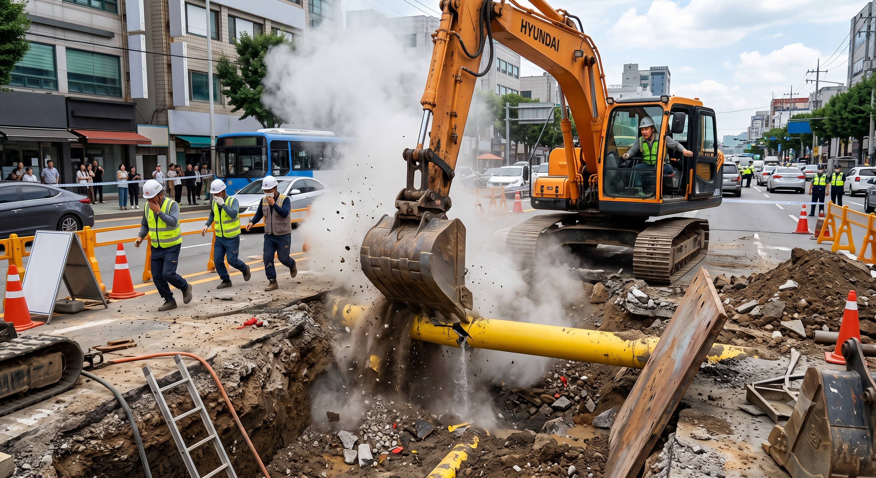
The original educational image is retained. It is not evidence of an actual incident or site suitability. The production method, including possible AI generation, and any real-incident origin have not been verified.
The scenario and record comparisons are fictional teaching examples, not records of real incidents, measurements, inspections, signatures or approvals.
| Item | Fictional scenario |
|---|---|
| Initial situation | A utility replacement crosses a poorly documented service corridor. |
| Changed condition | The drawing and surface marks disagree, while seepage appears in a trial pit. |
| Failure path | The foreman continues mechanical digging to recover time before support arrives. |
| Possible outcome | A bucket could strike a branch and the unsupported edge could fail under the machine; these are separate hazards that can escalate together. |
| Prevention barrier | Stop the bay, resolve the route with the owner, revise water and support arrangements, and release it only after inspection. No real injury, investigation or penalty is asserted. |
Failure mechanisms
A plan or detector trace estimates a route; it does not prove cover depth or identify every branch. Open the trial locations selected for the actual crossings and uncertainty before deciding where a bucket may travel.
Excavation changes confinement. Water pressure reduces effective stress and can transport fine soil; it does not make every soil's cohesion instantly zero. Surcharge effects depend on soil layers, load position and geometry, so a single setback cannot prove stability.
A shield protects occupants within its design limits but does not necessarily hold the surrounding ground in place. It cannot automatically protect adjacent foundations, support a suspended utility or make entry outside its ends safe. Lifting and repositioning require a protected sequence with personnel clear.
Decision sequence
| Decision stage | What to verify |
|---|---|
| Known facts | Confirm the intended cut, owners, responses and work limits before mobilizing into the bay. |
| Unresolved matters | Use plans, survey and controlled exposure together. An unknown service remains a stop condition even when a permit exists. |
| Reason to hold | Select support for soil, depth, water and all loads; verify compatibility with exposed services and adjacent structures. |
| Required evidence | Inspect assembly and access before entry. Keep people out of the bucket and lifting envelope; record actual conditions on the blank form. |
| Restart decision | After rain, movement, unknown obstructions or a changed cut, withdraw and reassess before a new release. Close with supported services, coordinated backfill and secure public protection. |
5. Conditional decisions and common errors
| Condition | Action | Evidence | Proceed when |
|---|---|---|---|
| Paint treated as depth | Combine plans and survey | Survey record | Service location resolved |
| Unknown line depth | Use owner-approved method | Actual line position | Exposure and protection verified |
| Wrong support model | Install from safe position | Support inspection | Support and entry released |
| Pump removes fines | Follow dewatering design | Water and soil trend | Dewatering reassessed |
| Supports pulled early | Coordinate support removal | Backfill sequence | Backfill and closure accepted |
Similar situations, different decisions
The scenario and record comparisons are fictional teaching examples, not records of real incidents, measurements, inspections, signatures or approvals.
| Comparison | Situation A | Situation B |
|---|---|---|
| Locate services | Paint treated as depth | Combine plans and survey |
| Expose services | Unknown line depth | Use owner-approved method |
| Support and enter | Wrong support model | Install from safe position |
| Control water | Pump removes fines | Follow dewatering design |
6. Roles and responsibilities
| Role | Responsibility |
|---|---|
| Work supervisor | Confirm the intended cut, owners, responses and work limits before mobilizing into the bay. After rain, movement, unknown obstructions or a changed cut, withdraw and reassess before a new release. Close with supported services, coordinated backfill and secure public protection. |
| Technical reviewer | Select support for soil, depth, water and all loads; verify compatibility with exposed services and adjacent structures. |
| Work crew | Use plans, survey and controlled exposure together. An unknown service remains a stop condition even when a permit exists. |
| Inspector / assessor | Inspect assembly and access before entry. Keep people out of the bucket and lifting envelope; record actual conditions on the blank form. |
Supervision, records, handover
| Job stage | Technical and procedural controls | Site verification |
|---|---|---|
| Plan the cut | 1. Assign utility liaison2. Accept support design3. Brief emergency plan | 1. Permit scope2. Soil and water data3. Emergency contacts |
| Locate services | 1. Log owner responses2. Resolve route discrepancies3. Retain survey evidence | 1. Survey record2. Owner conditions3. Marks and limits |
| Prepare plant | 1. Appoint plant spotter2. Log coupler defects3. Reject weak working areas | 1. Coupler test2. Platform condition3. Spotter signals |
| Expose services | 1. Witness service exposure2. Record depth and branches3. Release only proved area | 1. Actual line position2. Tool and jet settings3. Pit protection |
| Support and enter | 1. Check support design limits2. Record access inspection3. Control entry release | 1. Support inspection2. Access route3. Entry release |
| Backfill and close | 1. Agree backfill sequence2. Record service handback3. Assign barrier custody | 1. Backfill sequence2. Owner handback3. End-of-shift security |
7. Hold points and record comparison
| Hold point | Evidence before release | Confirmation / approval |
|---|---|---|
| Start | Open-cut excavation with an excavator near buried services, including trial exposure, staged support, entry and reinstatement. Release each bay only after the service position, ground support and working platform have been checked together. | |
| HP-1 Locate services | Survey record · Owner conditions · Marks and limits · Unidentified branches and changes recorded. | |
| HP-2 Expose services | Actual line position · Tool and jet settings · Pit protection · Owner attendance or isolation conditions met. | |
| HP-3 Support and enter | Support inspection · Access route · Entry release · Service-support design checked independently. | |
| HP-4 Backfill and close | Backfill sequence · Owner handback · End-of-shift security · As-built position and receiving party recorded. |
Complete after actual checks. Recheck after changes, defects or shift handover.
Record comparison examples
The scenario and record comparisons are fictional teaching examples, not records of real incidents, measurements, inspections, signatures or approvals.
The boxes are static record prompts, not interactive or saved approvals. A tick does not establish suitability or permission to restart. Record the evidence, person, time and unresolved issues; retain the change history.
| Record type | Insufficient record | Record checklist |
|---|---|---|
| Locate services | Inspected / OK only | □ Survey record□ Owner conditions□ Marks and limits□ Person, time, location and supporting evidence |
| Expose services | Inspected / OK only | □ Actual line position□ Tool and jet settings□ Pit protection□ Person, time, location and supporting evidence |
| Support and enter | Inspected / OK only | □ Support inspection□ Access route□ Entry release□ Person, time, location and supporting evidence |
| Backfill and close | Inspected / OK only | □ Backfill sequence□ Owner handback□ End-of-shift security□ Person, time, location and supporting evidence |
8. Site checklist and emergency response
| Check item | Result | Person / action |
|---|---|---|
| □ Plan the cut: Permit scope | ||
| □ Locate services: Survey record | ||
| □ Prepare plant: Coupler test | ||
| □ Expose services: Actual line position | ||
| □ Excavate in bays: Bay and depth | ||
| □ Support and enter: Support inspection | ||
| □ Control water: Water and soil trend | ||
| □ Backfill and close: Backfill sequence | ||
| □ Release / handover authority |
Stop work
Stop for unlocated services, damaged marks, lost communication, unsupported entry, new cracks, soil loss, rising water, gas odour or failed plant protection. A schedule deadline does not close these hold points.
Emergency response
Evacuate to a safe location, prevent approach, and call the site emergency team and asset owner from safety. Do not enter an unstable or contaminated trench to rescue. For suspected electrical contact keep others away and follow the utility emergency plan; do not approach the machine or cable.
9. Sources and review limits
2026-10-08
| Source | Scope and limitations |
|---|---|
| OSHA 1926.651 | Utility location, trench egress at 4 ft or more with maximum 25 ft lateral travel, water, atmospheric hazards and inspections. |
| OSHA 1926.652 | Protective systems, design data, installation and removal; shallow cuts may still need protection. |
This is reference content written and revised with AI. It has not been verified or approved by a professional. Review by a suitably qualified professional and site authorisation are required before use.
10. PDF guidance and FAQ
PDF A covers basic task controls; B focuses on technical failures; C covers supervision, records and handover. The article has eight stages with four items per main cell; each PDF has six key stages with three items per main cell. P/S/R/A, measurements, confirmations and signatures remain blank for actual site assessment.
Content group ID
jsa-excavation-works
Can marks or a drawing alone authorize the bucket?
No. Locate and expose by a suitable method, reconcile discrepancies and follow the owner and local requirements.
Does shallow depth mean entry is safe?
No. Collapse, surcharge, water and access must be assessed at the actual depth; statutory exceptions are conditional.
When must an open bay be reassessed?
After rain, ground movement, soil loss, a changed cut or changed loading, stop and obtain a fresh inspection and release.
Do hand tools remove electrical and gas risks?
No. Tools can still damage cables or coatings. Obtain the appropriate owner conditions, isolation where needed and safe exposure method.
Has a professional verified or approved this document?
No. Public sources and editorial, layout and consistency checks were reviewed using AI. No site inspection or professional technical approval has been performed. Obtain appropriate professional review before use.
11. Revision history and authorship
This is reference content written and revised with AI. It has not been verified or approved by a professional. Review by a suitably qualified professional and site authorisation are required before use.
| Date | Version | Change | Review status |
|---|---|---|---|
| 2026-07-21 | Original version unmarked | Original preserved | No professional approval |
| 2026-10-08 | 1.1 | Decisions, records, JSA and PDFs revised | No professional approval |
Retained the original useful themes of utility verification, coupler checks, exclusion zones, ground support and controlled close-out. Replaced unsupported universal numerical claims, invented incident outcomes and unverified expert approval. Original text, citations and available PDFs remain in the recovery files. New editorial revision 1.1 follows an unnumbered article baseline; the cited CGA edition is not a document version.
October 14, 2026 / body clarification: replaced five conditional-release placeholders with explicit evidence-based release labels. Existing PDF v1.1 and prior source-review dates retained. Editorial review only; no professional technical approval.