This revision follows the scaffold from the design brief and delivery through each stable erection stage to inspection, alteration and dismantling. A completed platform does not prove that the incomplete scaffold below it was stable during erection.
Prove the support, restraint and protected access at every changing stage
This is reference content written and revised with AI. It has not been verified or approved by a professional. Review by a suitably qualified professional and site authorisation are required before use.
Stop work
Stop the affected work and restrict access for settlement, leaning, an incomplete tie or brace, damaged or incompatible components, unplanned sheeting, unsafe electrical clearance, lost fall protection or weather outside the plan. Do not climb an unstable scaffold to repair it without a revised safe method.
1. Legal and technical scope
| Basis | Application limits |
|---|---|
| OSHA 1926.451 | Official support, access, inspection, supervision and fall-protection provisions reviewed. |
| HSE scaffolding | Foreign technical comparison only; UK intervals and credentials are not US requirements. |
Federal OSHA or the applicable State Plan must be identified. The provisions cited concern construction scaffolds, not a blanket design for every access structure.
1926.451 distinguishes design, support, access, use and fall protection. The 4:1 height-to-base condition triggers restraint provisions; it is not a complete tie layout. Inspections before each shift and after relevant events, and competent direction of erection/dismantling, must be addressed. The special erector/dismantler fall-protection assessment in (g)(2) is not an exemption from planning. ANSI/ASSP full texts and the actual manufacturer manual were not reviewed.
2. Scope and required inputs
Included scope
Ground-supported modular access scaffolds assembled by a trained crew under suitable supervision, with a known manufacturer configuration or a checked project design. Include delivery, foundations, connections, ties, platforms, containment, handover and controlled removal.
Separate review
Suspended scaffolds, mobile towers, cantilevers, temporary roofs, facade retention and load-bearing falsework require their own design and method. This article does not size anchors, sole boards, foundations or fall-arrest attachments, and does not authorise mixed systems.
| Required input | What to verify |
|---|---|
| Design brief | System and revision, geometry, working lifts, duty loads, hoists, public interfaces and all proposed mesh or sheeting. |
| Support evidence | Leg reactions, ground or slab capacity, buried services, drainage and any frost/thaw or excavation influence. |
| Restraint plan | Tie locations and duties, suitable substrate, anchor installation and test specification, permitted temporary untied height. |
| Crew and recovery | Competence, supervision, protected erection method, lifting plan, rescue arrangement and weather stop/restart criteria. |
The actual scaffold manual, ground report, anchor substrate, design drawings and local permits have not been supplied. The eight stages are assessment checkpoints: ties, bracing, access and edge protection must progress together as the approved erection sequence requires, not wait until a later numbered row.
3. Eight-stage JSA
| Job stage | Hazards and effects | Failure factors | Technical and procedural controls | Site verification | P | S | R | A |
|---|---|---|---|---|---|---|---|---|
| 1. Confirm design | 1. Collapse2. Overloading3. Electrical contact4. Public struck | 1. Wrong configuration2. Covering omitted3. Services missed4. No rescue plan | 1. Match design and duty2. Include mesh and hoists3. Plan service clearance4. Plan staged rescue | 1. Design revision2. Working lift loads3. Service controls4. Rescue method | ||||
| 2. Receive components | 1. Bundle rolls2. Hands crushed3. Back strain4. Part falls | 1. Loose restraint2. Mixed systems3. Damaged part4. Poor handling | 1. Separate unloading2. Check compatible parts3. Quarantine defects4. Use handling aids | 1. Delivery inventory2. System markings3. Part condition4. Handling route | ||||
| 3. Prepare bases | 1. Leg settlement2. Scaffold tilts3. Jack buckles4. Slab fails | 1. Weak ground2. Poor sole support3. Excess extension4. Unknown slab | 1. Verify bearing support2. Fit planned bases3. Set jacks by manual4. Check level and plumb | 1. Support evidence2. Base contact3. Jack engagement4. Initial geometry | ||||
| 4. Erect and brace | 1. Frame racks2. Member falls3. Erector falls4. Joint separates | 1. Brace omitted2. Lock not seated3. Unsafe access4. Forced mixed part | 1. Brace each stage2. Secure all joints3. Use protected method4. Keep people clear | 1. Brace layout2. Joint engagement3. Access protection4. System compatibility | ||||
| 5. Install ties | 1. Scaffold tips2. Anchor pulls out3. Wall fails4. Drill contact | 1. Tie delayed2. Weak substrate3. Wrong anchor4. Services hidden | 1. Tie as work rises2. Use specified anchors3. Follow test plan4. Check drilling area | 1. Tie positions2. Substrate evidence3. Anchor records4. Temporary free height | ||||
| 6. Fit decks and access | 1. Fall through gap2. Deck lifts3. Tool falls4. Rescue delayed | 1. Deck not retained2. Open edge3. Unsafe ladder4. Unverified anchor | 1. Secure deck retention2. Install edge protection3. Provide safe access4. Verify fall system | 1. Deck locks2. Guardrails and gaps3. Access route4. Clearance and rescue | ||||
| 7. Cover, inspect, release | 1. Wind overturning2. Debris strikes3. Deck overload4. Defect concealed | 1. Unplanned mesh2. Weak fastener3. Wrong duty4. Checks incomplete | 1. Approve cover design2. Use specified fixings3. Inspect and close defects4. Communicate use limits | 1. Cover and ties2. Fixing specification3. Inspection record4. Load and use limits | ||||
| 8. Alter or dismantle | 1. Remaining frame falls2. Erector falls3. Part drops4. Public enters | 1. Ties removed early2. Access lost3. Parts thrown4. Poor exclusion | 1. Plan stable sequence2. Retain needed ties3. Lower parts safely4. Restrict altered areas | 1. Removal stage2. Remaining bracing3. Protected access4. Closure and handover |
PDF A covers basic task controls; B focuses on technical failures; C covers supervision, records and handover. The article has eight stages with four items per main cell; each PDF has six key stages with three items per main cell. P/S/R/A, measurements, confirmations and signatures remain blank for actual site assessment.
4. Fictional scenario and failure mechanisms
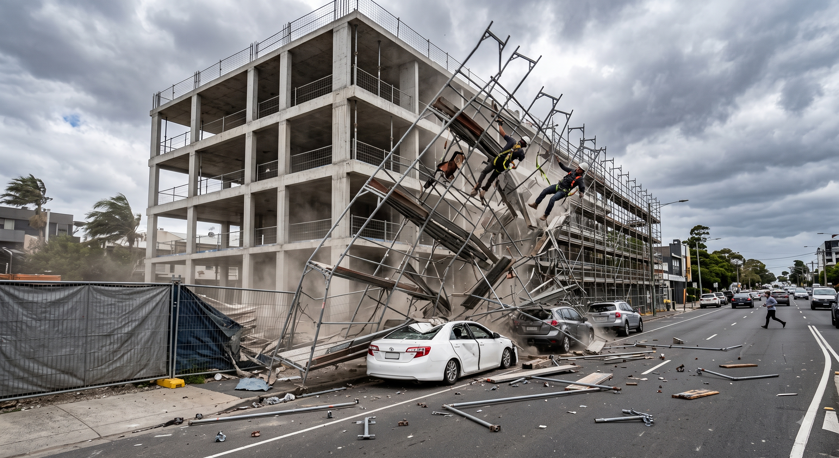
The original educational image is retained. It is not evidence of an actual incident or site suitability.
The scenario and record comparisons are fictional teaching examples, not records of real incidents, measurements, inspections, signatures or approvals.
| Item | Fictional scenario |
|---|---|
| Initial situation | A fictional crew has completed several lifts but one planned tie location is unavailable; another trade requests dense mesh before handover. |
| Changed condition | The missing tie and proposed covering are known. The substituted anchor substrate, temporary stability and revised wind forces are not demonstrated. |
| Failure path | A green tag from an earlier configuration would not resolve these gaps. Adding mesh and progressing upward are held. |
| Possible outcome | The designer resolves the restraint arrangement and covering, and the crew installs and records the specified anchors, braces and stage limits. |
| Prevention barrier | A suitable inspector checks the actual configuration against the revised design before access is released. The example supplies no measured capacity or real approval. |
Failure mechanisms
Gravity travels through decks, ledgers, standards and base supports; lateral forces need a complete restraint path. An omitted brace can permit frame racking even where the scaffold remains visually upright. A wall tie is a lateral restraint, not a substitute for every missing structural member.
For an ideal elastic column with otherwise unchanged end conditions, Euler critical load varies with 1/(effective length squared). Doubling that length gives one quarter of that ideal critical load. This is neither an exponential law nor an allowable-load calculation for a real scaffold with joints, imperfections and combined bending.
A screening estimate of average bearing pressure is leg force divided by effective bearing area. It does not prove that the full plan area of a flexible sole board is effective, or that a slab, trench edge or thawing subgrade can support the reactions. Differential settlement changes geometry and redistributes loads.
Mesh and sheeting change wind actions on the scaffold and its anchors; porosity does not make their effect zero. Decks or ordinary debris netting do not replace guardrails or a designed fall-arrest system. Personal protection requires verified attachments, clearance and rescue, including at the low first lifts.
Decision sequence
| Decision stage | What to verify |
|---|---|
| Known facts | Identify the exact configuration and whether its dimensions, duty and covering are within the supplied design. |
| Unresolved matters | Locate the affected leg, connection or anchor, the work already erected above it and the trades exposed below. |
| Reason to hold | Hold the next lift or altered loading until the missing support, restraint or protection has a valid solution. |
| Required evidence | Collect the design revision, installation and test records, component checks and evidence that defects are closed. |
| Restart decision | Release only the inspected scope with load and use restrictions; a later alteration or significant weather event starts a new review. |
5. Conditional decisions and common errors
| Condition | Action | Evidence | Proceed when |
|---|---|---|---|
| Tie unavailable | Hold the next lift; resolve restraint | Revised layout and verified anchorage | Restraint complete |
| Covering added | Review wind and tie demand | Design including mesh or sheet | Covering allowed |
| Settlement seen | Restrict access and assess support | Cause, repair and geometry checks | Support verified |
| Alter or dismantle | Plan the changing support state | Removal sequence and protected access | Stable next stage |
Similar situations, different decisions
The scenario and record comparisons are fictional teaching examples, not records of real incidents, measurements, inspections, signatures or approvals.
| Comparison | Situation A | Situation B |
|---|---|---|
| Same green tag | Tag relates to yesterday’s open scaffold; today mesh and a hoist are added. | Configuration has been reassessed and inspection identifies the allowed load, covering and users. |
| Same test result | One pull-out value is used to approve every anchor in varying substrate. | Test locations, method and acceptance follow the design and results are traceable to the actual anchors. |
| Same harness | Worker clips to an unverified ledger with insufficient clearance. | The planned erection method prioritises collective protection and verifies any necessary personal system and rescue. |
6. Roles and responsibilities
| Role | Responsibility |
|---|---|
| Responsible contractor | Supply the design brief, coordinate utilities and other trades, and provide competent personnel and rescue resources. |
| Designer / engineer | Resolve support reactions, restraint, coverings and departures from the manufacturer configuration, including temporary stages. |
| Erection supervisor | Brief and enforce the stage sequence, verify ties and bracing as work rises, and keep incomplete areas restricted. |
| Erection crew | Check compatible parts, secure connections and decks, maintain protected access, and report defects without unauthorised substitution. |
| Inspector / user representative | Record configuration and limits, close defects before release, and arrange further checks after changes or damaging events. |
Supervision, records, handover
| Job stage | Technical and procedural controls | Site verification |
|---|---|---|
| Accept design | 1. Confirm design scope2. Set loading limits3. Arrange rescue | 1. Drawing revision2. Load schedule3. Rescue plan |
| Accept support | 1. Review leg reactions2. Check support evidence3. Accept base layout | 1. Ground or slab record2. Base positions3. Jack configuration |
| Release stages | 1. Verify stage stability2. Check ties and joints3. Confirm protection | 1. Stage checklist2. Tie records3. Protected route |
| Control covering | 1. Review added loads2. Approve attachment3. Restrict changes | 1. Covering design2. Anchor duties3. Fixing record |
| Handover use | 1. Close defects2. State use restrictions3. Record inspection | 1. Inspection scope2. Load limits3. Receiving person |
| Control removal | 1. Maintain restraints2. Review removal stages3. Secure site closure | 1. Removal plan2. Access controls3. Closure record |
7. Hold points and record comparison
| Hold point | Evidence before release | Confirmation / approval |
|---|---|---|
| Start | Ground-supported modular access scaffolds assembled by a trained crew under suitable supervision, with a known manufacturer configuration or a checked project design. Include delivery, foundations, connections, ties, platforms, containment, handover and controlled removal. | |
| HP-1 Prepare bases | Support evidence · Base contact · Jack engagement · Initial geometry | |
| HP-2 Install ties | Tie positions · Substrate evidence · Anchor records · Temporary free height | |
| HP-3 Cover, inspect, release | Cover and ties · Fixing specification · Inspection record · Load and use limits | |
| HP-4 Alter or dismantle | Removal stage · Remaining bracing · Protected access · Closure and handover |
Complete after actual checks. Recheck after changes, defects or shift handover.
Record comparison examples
The scenario and record comparisons are fictional teaching examples, not records of real incidents, measurements, inspections, signatures or approvals.
The boxes are static record prompts, not interactive or saved approvals. A tick does not establish suitability or permission to restart. Record the evidence, person, time and unresolved issues; retain the change history.
| Record type | Insufficient record | Record checklist |
|---|---|---|
| Foundation | Ground looks firm | □ Leg locations□ Support design□ Ground or slab evidence□ Settlement checks |
| Ties | Anchors tested | □ Tie drawing revision□ Anchor and substrate IDs□ Specified test and result□ Defects and resolution |
| Handover | Green tag fitted | □ Inspected configuration□ Permitted loads and lifts□ Covering and restrictions□ Inspector and recipient |
| Alteration | One tie removed | □ Reason and location□ Revised stability method□ Affected access restriction□ Reinspection and release |
8. Site checklist and emergency response
| Check item | Result | Person / action |
|---|---|---|
| □ Confirm design: Design revision | ||
| □ Receive components: Delivery inventory | ||
| □ Prepare bases: Support evidence | ||
| □ Erect and brace: Brace layout | ||
| □ Install ties: Tie positions | ||
| □ Fit decks and access: Deck locks | ||
| □ Cover, inspect, release: Cover and ties | ||
| □ Alter or dismantle: Removal stage | ||
| □ Release / handover authority |
Stop work
Stop the affected work and restrict access for settlement, leaning, an incomplete tie or brace, damaged or incompatible components, unplanned sheeting, unsafe electrical clearance, lost fall protection or weather outside the plan. Do not climb an unstable scaffold to repair it without a revised safe method.
Emergency response
Keep people away from the collapse or dropped-object area, call the site emergency response and prevent unplanned entry. A suspended worker needs the planned rescue by a trained team; an incomplete or damaged scaffold is not automatically a rescue anchor. Do not pull out ties or straighten loaded members during rescue improvisation.
9. Sources and review limits
2026-10-08
| Source | Scope and limitations |
|---|---|
| OSHA 1926.451 | Official support, access, inspection, supervision and fall-protection provisions reviewed. |
| HSE scaffolding | Foreign technical comparison only; UK intervals and credentials are not US requirements. |
This is reference content written and revised with AI. It has not been verified or approved by a professional. Review by a suitably qualified professional and site authorisation are required before use.
10. PDF guidance and FAQ
PDF A covers basic task controls; B focuses on technical failures; C covers supervision, records and handover. The article has eight stages with four items per main cell; each PDF has six key stages with three items per main cell. P/S/R/A, measurements, confirmations and signatures remain blank for actual site assessment.
Content group ID
jsa-erecting-scaffolding
Can mesh be installed after inspection without another check?
No. Its effect on wind loads, restraint and attachments must be covered by the design and the actual changed arrangement must be checked.
Does a green tag establish structural capacity?
No. It communicates status; the design, installation evidence, inspection record and current configuration establish the basis for use.
Are all screw jacks limited to 300 mm?
No universal value is provided here. Apply the actual manufacturer and applicable legal requirements to the jack, engagement and configuration.
May ties be removed early for facade finishing?
Only through a controlled alteration plan that maintains stability and protection throughout; do not remove them simply because the work deck is finished.
Has a professional verified or approved this document?
No. Public sources and editorial, layout and consistency checks were reviewed using AI. No site inspection or professional technical approval has been performed. Obtain appropriate professional review before use.
11. Revision history and authorship
This is reference content written and revised with AI. It has not been verified or approved by a professional. Review by a suitably qualified professional and site authorisation are required before use.
| Date | Version | Change | Review status |
|---|---|---|---|
| 2026-08-17 | Original version unmarked | Original preserved | No professional approval |
| 2026-10-08 | 1.1 | Decisions, records, JSA and PDFs revised | No professional approval |
Useful unloading, foundations, joint locking, bracing, fall protection, tie installation and inspection controls are retained. Blanket two-person lifting, universal jack or anchor dimensions, arbitrary hammer weights, fixed proof-test multipliers and cable-tie specifications are replaced by assessed and specified methods. The original hypothetical deaths and regulator findings are replaced by an explicitly fictional decision exercise. Automatic engineering calculation, complete compliance and pre-approved risk scores are not claimed.