Binder quantity alone does not establish column performance. Link soil conditions, mixing uniformity, depth/time logs, samples, curing and the intended loading. A good total injection figure can conceal a deficient interval.
This is reference content written and revised with AI. It has not been verified or approved by a professional. Review by a suitably qualified professional and site authorization are required before use.
Stop before starting
Stop for rig tilt or settlement, abrupt resistance/soil changes, suspected utility contact, slurry pressure/flow anomalies, leaks or interrupted records. Mark the affected column and depth; do not conceal a gap in an average.
1. Legal and technical scope
| Basis | Scope and limits |
|---|---|
| OSHA 1926.602 | Equipment-class applicability and safe access roadways/grades; no universal rig platform design. |
| OSHA wet cement guidance | Cement-contact exposure prevention; actual binder SDS controls product selection. |
| FHWA deep-mixing manual | Project-specific design, trials, monitoring and quality verification guidance. |
| FHWA Chapter 9 | Specifications, plans and contractor submittals; not a prescribed mix for this site. |
Apply construction equipment, chemical, guarding and exposure requirements to the actual rig and process; do not assume every deep-mixing rig is a crane or the same equipment class. 1926.602 addresses covered equipment and safe access roads/grades. FHWA deep-mixing guidance informs project design and quality planning but is not a universal OSHA mix, pressure or acceptance limit. State Plan and project requirements must be resolved.
2. Scope and required inputs
Included work
Land-based wet deep mixing: rig setup, binder slurry production and feed, penetration, mixing and withdrawal, adjoining columns, quality testing and curing handover. DCM here means deep cement mixing.
Separate assessment
Jet grouting, dry mixing and marine work need separate plans. Changes to soil, binder, sequence or travel route require review of the trial and design assumptions.
| Required input | Evidence to obtain |
|---|---|
| Review ground and trials | Soil and utilities; Trial applicability; Column geometry; Testing and loading |
| Set platform and rig | Platform support; Setup and travel loads; Route review; Mast clearance |
| Prepare slurry system | Binder and SDS; Hose and guarding; Meter condition; Batch and lot identity |
| Position and penetrate | Shaft exclusion; Resistance and tilt; Column location; Logging function |
No actual equipment model, SDS, site measurements, design calculations or authorization record was supplied. Product-specific limits and methods must be verified before use. Federal OSHA is a baseline within its scope; determine the applicable State Plan and local requirements. Manufacturer guidance is not government approval; an incorporated standard differs from voluntary guidance. No nationwide-compliance or expert-approval claim is made.
3. Eight-stage JSA
| Job stage | Hazards and effects | Failure factors | Technical and procedural controls | Site verification | P | S | R | A |
|---|---|---|---|---|---|---|---|---|
| 1. Review ground and trials | 1. Weak treatment2. Utility damage3. Ground movement4. Early loading | 1. Soil changes missed2. Depth overlap wrong3. Assets unmapped4. Curing plan missing | 1. Link soils and trials2. Approve layout and tests3. Survey affected assets4. Set loading restrictions | 1. Soil and utilities2. Trial applicability3. Column geometry4. Testing and loading | ||||
| 2. Set platform and rig | 1. Rig overturn2. Platform settlement3. Travel collapse4. Overhead contact | 1. Bearing inadequate2. Fresh ground relied on3. Route improvised4. Mast clearance unknown | 1. Verify actual rig loads2. Check platform drainage3. Use accepted routes4. Control overhead interface | 1. Platform support2. Setup and travel loads3. Route review4. Mast clearance | ||||
| 3. Prepare slurry system | 1. Cement contact2. Hose release3. Mixer entanglement4. Wrong binder mix | 1. SDS not checked2. Hose damage3. Guard removed4. Meter fault | 1. Use contained transfer2. Inspect hose and tanks3. Guard mixer access4. Verify binder and meters | 1. Binder and SDS2. Hose and guarding3. Meter condition4. Batch and lot identity | ||||
| 4. Position and penetrate | 1. Rotating shaft contact2. Utility strike3. Rig tilt4. Missing records | 1. People near shaft2. Resistance ignored3. Reference moved4. Logger not working | 1. Exclude shaft zone2. Watch ground response3. Check position reference4. Verify depth-time log | 1. Shaft exclusion2. Resistance and tilt3. Column location4. Logging function | ||||
| 5. Mix and withdraw | 1. Slurry escape2. Uneven treatment3. Missed interruption4. Entanglement | 1. Flow mix mismatch2. Leak ignored3. Only total checked4. Live shaft cleaning | 1. Maintain approved method2. Record flow with depth3. Mark anomalous intervals4. Prevent live access | 1. Mix and flow record2. Depth and time3. Pressure anomalies4. Withdrawal record | ||||
| 6. Check adjacent work | 1. Ground heave2. Rig settlement3. Defect concealed4. Sample mix-up | 1. Sequence changed2. Early loading3. Overlap missed4. Sample ID absent | 1. Track sequence and overlap2. Check curing and movement3. Mark nonconformity4. Link samples to columns | 1. Sequence and overlap2. Movement observations3. Curing and tests4. Sample traceability | ||||
| 7. Clear faults safely | 1. Trapped pressure2. Unexpected rotation3. Gravity release4. Supply re-entry | 1. Live hose opening2. Interlock bypass3. Slurry head ignored4. Feed not isolated | 1. Stop and isolate2. Verify pressure controlled3. Control gravity paths4. Prevent renewed feed | 1. Isolation and no pressure2. Maintenance method3. Waste containment4. Guard restoration | ||||
| 8. Release and hand over | 1. Premature loading2. Undetected movement3. Wrong test applied4. Route failure | 1. Results not mapped2. Use before acceptance3. Limits unclear4. Platform not checked | 1. Link tests to locations2. Resolve deficient columns3. Transfer load restrictions4. Verify route separately | 1. Column acceptance2. Curing and load limits3. Outstanding actions4. Platform recipient |
P = likelihood; S = severity; R = risk under the site method; A = site-defined acceptance/authorization. These actual assessment cells are blank. A low score never overrides a missing safeguard or a legal or manufacturer restriction.
4. Fictional scenario and failure mechanisms
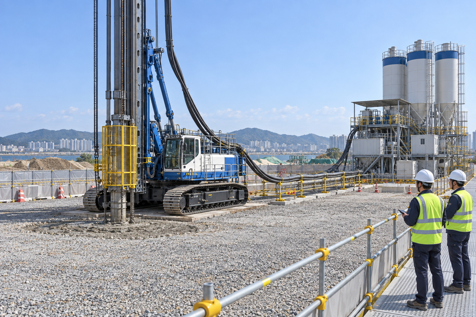
This illustration provides educational context. It is not an actual incident photograph or evidence of equipment suitability; any AI-generated depiction is illustrative only.
The scenario and record comparisons are fictional teaching examples, not records of real incidents, measurements, inspections, signatures or approvals.
| Stage | Fictional situation |
|---|---|
| Initial situation | A fictional deep-mixing crew completes a row of columns. |
| Changed condition | The rig route is moved onto the previous day's treatment before required testing and curing. |
| Failure path | Future improved-ground performance is mistaken for immediate track support. |
| Possible outcome | Settlement could tilt the mast and strain hoses or overturn the rig. |
| Prevention barrier | Hold the new route; independently verify platform support under the actual rig loads and resolve column-quality release. |
Failure mechanisms
Binder quantity alone does not establish column performance. Link soil conditions, mixing uniformity, depth/time logs, samples, curing and the intended loading. A good total injection figure can conceal a deficient interval.
A tall-mast rig needs a working platform verified for setup, operating and travel loads. The eventual design strength of treated ground does not prove that yesterday's columns can support today's travel. Keep movement on the accepted route until revised support and curing conditions are reviewed.
A stopped slurry pump can leave pressure behind a blockage. Before any opening, designated personnel control supply re-entry, rotation, pressure and gravity under the actual procedure. Wet binder also requires contact protection, washing and controlled waste handling.
Work sequence: Review ground and trials → Set platform and rig → Prepare slurry system → Position and penetrate → Mix and withdraw → Check adjacent work → Clear faults safely → Release and hand over. This is a teaching flow, not a device drawing or a complete operating procedure.
5. Conditional decisions and common errors
| Situation | Required action | Evidence | Proceed when |
|---|---|---|---|
| Route changes | Hold rig movement | Platform and load review | Route accepted |
| Flow or log gap | Mark affected interval | Column ID, depth and time | Disposition assigned |
| Hose blockage | Isolate before opening | No feed, pressure or rotation | Safe condition verified |
| Next loading proposed | Review curing and tests | Location-specific results | Loading released |
Similar observations, different decisions
The scenario and record comparisons are fictional teaching examples, not records of real incidents, measurements, inspections, signatures or approvals.
| Observation | Insufficient conclusion | Required distinction |
|---|---|---|
| Installed quantity | Production total | Quality and depth uniformity separate |
| Treated yesterday | Binder placed | Immediate bearing unproved |
| Pump stopped | Drive stopped | Trapped slurry may remain |
6. Roles and responsibilities
| Role | Responsibility |
|---|---|
| Work supervisor | Confirm soil and utilities and the task scope, resources, interfaces and stop authority. |
| Qualified technical reviewer | Review platform support, model limits, compatibility and unresolved technical conditions within assigned competence. |
| Work crew | Apply the listed controls, report changes and stop when evidence or safeguards are missing. |
| Inspector / assessor | Record actual mix and flow record and other relevant checks; do not mark unverified conditions as accepted. |
| Handover authority | Reconcile column acceptance, restrictions and outstanding actions before the next task. Role labels do not establish a legal credential. |
Supervision and handover focus
| Stage | Management action | Evidence |
|---|---|---|
| Review ground and trials | 1. Record soil and utilities2. Record trial applicability3. Record column geometry | 1. Soil and utilities2. Trial applicability3. Column geometry |
| Set platform and rig | 1. Record platform support2. Record setup and travel loads3. Record route review | 1. Platform support2. Setup and travel loads3. Route review |
| Position and penetrate | 1. Record shaft exclusion2. Record resistance and tilt3. Record column location | 1. Shaft exclusion2. Resistance and tilt3. Column location |
| Mix and withdraw | 1. Record mix and flow record2. Record depth and time3. Record pressure anomalies | 1. Mix and flow record2. Depth and time3. Pressure anomalies |
| Clear faults safely | 1. Record isolation and no pressure2. Record maintenance method3. Record waste containment | 1. Isolation and no pressure2. Maintenance method3. Waste containment |
| Release and hand over | 1. Record column acceptance2. Record curing and load limits3. Record outstanding actions | 1. Column acceptance2. Curing and load limits3. Outstanding actions |
7. Hold points and record comparison
| Hold point | Evidence before release | Actual approval |
|---|---|---|
| HP-0 Scope | Land-based wet deep mixing: rig setup, binder slurry production and feed, penetration, mixing and withdrawal, adjoining columns, quality testing and curing handover. DCM here means deep cement mixing. | |
| HP-1 Set platform and rig | Platform support; Setup and travel loads; Route review; Mast clearance | |
| HP-2 Position and penetrate | Shaft exclusion; Resistance and tilt; Column location; Logging function | |
| HP-3 Clear faults safely | Isolation and no pressure; Maintenance method; Waste containment; Guard restoration | |
| HP-4 Release and hand over | Column acceptance; Curing and load limits; Outstanding actions; Platform recipient |
Hold points are internal project checks. They are not universal statutory permits and do not grant work permission. Reassess after defects, changed conditions and shift changes.
Record comparison
The scenario and record comparisons are fictional teaching examples, not records of real incidents, measurements, inspections, signatures or approvals.
The boxes are static record prompts, not interactive or saved approvals. A tick does not establish suitability or permission to restart. Record the evidence, person, time and unresolved issues; retain the change history.
| Record | Insufficient record | Record checklist |
|---|---|---|
| Review ground and trials | Only marked “OK” | □ Soil and utilities□ Trial applicability□ Column geometry□ Testing and loading |
| Position and penetrate | Only marked “OK” | □ Shaft exclusion□ Resistance and tilt□ Column location□ Logging function |
| Clear faults safely | Only marked “OK” | □ Isolation and no pressure□ Maintenance method□ Waste containment□ Guard restoration |
| Release and hand over | Only marked “OK” | □ Column acceptance□ Curing and load limits□ Outstanding actions□ Platform recipient |
8. Site checklist and emergency response
| Site check | Actual result | Person / action |
|---|---|---|
| Review ground and trials: Soil and utilities; Trial applicability; Column geometry; Testing and loading | ||
| Set platform and rig: Platform support; Setup and travel loads; Route review; Mast clearance | ||
| Prepare slurry system: Binder and SDS; Hose and guarding; Meter condition; Batch and lot identity | ||
| Position and penetrate: Shaft exclusion; Resistance and tilt; Column location; Logging function | ||
| Mix and withdraw: Mix and flow record; Depth and time; Pressure anomalies; Withdrawal record | ||
| Check adjacent work: Sequence and overlap; Movement observations; Curing and tests; Sample traceability | ||
| Clear faults safely: Isolation and no pressure; Maintenance method; Waste containment; Guard restoration | ||
| Release and hand over: Column acceptance; Curing and load limits; Outstanding actions; Platform recipient |
Stop work
Stop for rig tilt or settlement, abrupt resistance/soil changes, suspected utility contact, slurry pressure/flow anomalies, leaks or interrupted records. Mark the affected column and depth; do not conceal a gap in an average.
Emergency response
Clear the rig and pressurized-hose danger zones and summon the site emergency response. Do not approach a leaning mast or loosen a pressurized blockage. Use the binder SDS for contact response; trained personnel stabilize and isolate before recovery.
9. Sources and review limits
Public-source access/review: 2026-10-12.
| Official source | Reviewed scope and limits |
|---|---|
| OSHA 1926.602 | Equipment-class applicability and safe access roadways/grades; no universal rig platform design. |
| OSHA wet cement guidance | Cement-contact exposure prevention; actual binder SDS controls product selection. |
| FHWA deep-mixing manual | Project-specific design, trials, monitoring and quality verification guidance. |
| FHWA Chapter 9 | Specifications, plans and contractor submittals; not a prescribed mix for this site. |
No actual equipment model, SDS, site measurements, design calculations or authorization record was supplied. Product-specific limits and methods must be verified before use. Federal OSHA is a baseline within its scope; determine the applicable State Plan and local requirements. Manufacturer guidance is not government approval; an incorporated standard differs from voluntary guidance. No nationwide-compliance or expert-approval claim is made.
10. PDF guidance and FAQ
PDF A covers basic task controls; B focuses on technical failures; C covers supervision, records and handover. P/S/R/A, measurements, confirmations and signatures remain blank for actual site assessment.
PDFs are complementary six-stage extracts. Apply all eight body stages and the actual equipment/site procedure.
Does DCM refer to a cleaning chemical here?
No. This article covers wet deep cement mixing for ground improvement.
Can a total binder figure prove a column acceptable?
No. Reconcile depth/time process records, testing and project acceptance criteria.
Who sets pressure and mixing rates?
The approved project design, trials and actual equipment method; this article supplies no universal operating settings.
Has a professional verified or approved this document?
No. Public sources and editorial, layout and consistency checks were reviewed using AI. No site inspection or professional technical approval has been performed. Obtain appropriate professional review before use.
11. Revision history and authorship
This is reference content written and revised with AI. It has not been verified or approved by a professional. Review by a suitably qualified professional and site authorization are required before use.
| Date | Version | Change | Review status |
|---|---|---|---|
| 2026-10-12 | US 1.0 | New US edition from assigned Korean source; task decisions, records and PDFs localized. | AI editorial review; no professional technical approval |
Korean edition revision dates: 2026-03-02, 2026-08-01, 2026-09-19, 2026-09-26. US v1.0 adapts the earlier edition to United States requirements and terminology.
Site reviewers must add their actual qualifications, scope, date and approval only after the review occurs.