Control the temporary load path before allowing the next movement. This revision links the existing crane-specific hazards to evidence at connection opening, each hydraulic stroke, mast insertion and final release. The eight rows group activities; they do not prescribe the mechanical sequence for an unidentified crane.
This is reference content written and revised with AI. It has not been verified or approved by a professional. Review by a suitably qualified professional and site authorisation are required before use.
Stop work
Stop for missing support confirmation, abnormal pressure or movement, guide binding, loss of communication, weather outside the approved envelope, an incomplete connection or entry into the exposure zone. Stop progressing the sequence; keep the system in its prescribed holding condition.
1. Legal and technical scope
| Basis | Application limits |
|---|---|
| OSHA - 29 CFR 1926.1435 | Reviewed climbing, wind, supports, ballast, hydraulic safety devices, wind-speed indication and inspection provisions. No universal wind limit or permit form is inferred. |
United States: federal OSHA Subpart CC is the baseline; verify State Plan and local duties. Under 1926.1435, climbing invokes 1403-1406, supports need the specified design and the host structure requires RPE verification. The original wind-indicator reference 1926.1435(e)(5)(v) is corrected to (e)(6)(v); (e)(5)(v) concerns load moment limiting. ASME full text was not reviewed.
2. Scope and required inputs
Use the exact manufacturer climbing manual, approved configuration and jurisdiction-specific engineering documents. No actual model manual or site calculations were supplied. Do not infer wind limits, torque, support capacity, free-standing height or a pin-removal sequence from this guide. A support may carry hydraulic load during a prescribed stroke; mechanical transfer is required at the stages specified for that system.
| Required input | What to verify |
|---|---|
| Plan | Does the manual number and revision match the installed crane?; Are all required engineering documents approved and available?; Have the crew's qualifications and assigned responsibilities been verified?; Are the permit package and required attachments complete? |
| Weather | Is the controlling wind limit and measurement basis recorded?; Is the wind indicator functioning and visible to responsible personnel?; Do the forecast and current conditions permit safe completion or securing?; Do the barricades match the approved restricted-area drawing? |
| Inspect | Has the required component inspection been documented?; Did the hydraulic system pass the specified functional or pressure test?; Are all components identified and compatible with the installed system?; Have all safety-related deficiencies been formally closed? |
| Balance | Does the counterweight and ballast match the approved configuration?; Are the balance load, trolley radius, and jib orientation correct?; Is the specified slew-restraint method fully applied?; Are level, plumb, connection-gap, and guide-clearance criteria acceptable? |
| Each stroke | Are the load-transfer supports fully seated and retained as specified?; Are hydraulic pressure, cylinder position, and guide alignment normal?; Are personnel clear of shear, pinch, and potential movement zones?; Has the A/D Director released the hold point for this stroke? |
| Insert | Are the mast-section ID, weight, lifting points, and compatibility verified?; Has the rigging passed inspection and been installed by a qualified rigger?; Are transfer-device stops and retainers correctly installed?; Are personnel maintaining clearance from all pinch and crush zones? |
| Connect | Does every bolt, nut, pin, washer, and retainer meet the specification?; Is required tooling identified, inspected, and within its calibration period?; Are torque, tension, pin engagement, or other acceptance results recorded?; Has an independent qualified checker accepted every required connection? |
| Release | Does the final crane configuration match the approved plan?; Are required inspections, tests, and plumb checks complete?; Have all personnel, tools, and temporary components been accounted for?; Has the A/D Director and responsible site representative authorized return to service? |
This JSA applies to planned top-climbing or internal-climbing operations that change the tower crane configuration or elevation.
It must be revised when the actual work includes a different climbing system, self-erecting crane, external climbing frame, tie-in removal, structural modification, major repair, or another configuration not covered by the approved plan.
Required Permit Attachments
- Crane manufacturer, model, serial number, and current configuration
- Climbing-system model and identification
- Current manufacturer erection and climbing manual
- Applicable manufacturer technical bulletins
- Site-specific climbing sequence
- Component and mast-section list
- A/D Director designation
- Crew qualification records
- RPE-approved support, brace, tie-in, anchorage, and host-structure documents
- Required inspection reports and deficiency closeout records
- Manufacturer wind limit or documented qualified-person determination
- Mid-climb securing and emergency procedure
- Fall-protection and rescue plan
- Rigging plan and qualified-rigger designation
- Restricted-area and fall-zone drawing
- Communication and emergency-stop plan
- Power-line assessment and controls
- Mast-section and connection-hardware acceptance records
3. Eight-stage JSA
| Job stage | Hazards and effects | Failure factors | Technical and procedural controls | Site verification | P | S | R | A |
|---|---|---|---|---|---|---|---|---|
| 1. Plan | 1. Use of an incorrect procedure or crane configuration causing structural instability2. Failure of the host structure, tie-ins, braces, or anchorages3. Electrical contact, collision, or interference with simultaneous operations4. Catastrophic collapse caused by uncoordinated work or unqualified direction | 1. Using a manual for a different crane model, climbing system, or revision2. Starting work without required RPE calculations and drawings3. Failing to identify manufacturer prohibitions and mandatory hold points4. Assigning personnel without documented task-specific qualifications | 1. Verify the crane make, model, serial number, climbing system, and current configuration2. Apply 29 CFR 1926.1403–1926.1406 through §1926.14353. Obtain required manufacturer, registered Professional Engineer, and authority approvals4. Designate the A/D Director, operator, qualified rigger, signal person, qualified persons, and rescue personnel | 1. Does the manual number and revision match the installed crane?2. Are all required engineering documents approved and available?3. Have the crew's qualifications and assigned responsibilities been verified?4. Are the permit package and required attachments complete? | ||||
| 2. Weather | 1. Wind-induced rotation, climbing-frame racking, or loss of balance2. Lightning, icing, precipitation, or poor visibility affecting climbing control3. Workers or members of the public entering the fall or collapse zone4. Struck-by injury from falling tools, hardware, or structural components | 1. Applying a generic 20 mph limit instead of the controlling manufacturer limit2. Using ground-level estimates without verifying the tower wind-speed display3. Failing to define a mid-climb securing and restart procedure4. Using an arbitrary fixed-radius barricade that does not cover credible exposure | 1. Record the manufacturer wind limit or qualified-person determination required by §1926.1435(b)(4)(iii)2. Apply any lower project, authority, or engineered limit3. Continuously monitor wind and define warning, stop, securing, and restart criteria4. Barricade the restricted area using the actual drop, swing, transfer, and collapse envelopes | 1. Is the controlling wind limit and measurement basis recorded?2. Is the wind indicator functioning and visible to responsible personnel?3. Do the forecast and current conditions permit safe completion or securing?4. Do the barricades match the approved restricted-area drawing? | ||||
| 3. Inspect | 1. Damaged mast, climbing frame, guide system, or work platform2. Hydraulic hose rupture, fluid injection, or uncontrolled cylinder movement3. Failure of a load-supporting check valve or pressure-limiting device4. Worn or incompatible supports, pins, retainers, rollers, or components | 1. Performing only a visual walkaround without task-specific inspection2. Operating with leakage, damaged hoses, abnormal pressure, or contaminated fluid3. Failing to verify check valves, pressure limits, retainers, and positive stops4. Allowing rejected, unidentified, or incompatible components into the work area | 1. Require a qualified-person inspection under the applicable OSHA and manufacturer provisions2. Inspect pumps, cylinders, hoses, fittings, controls, check valves, and pressure-limiting devices3. Inspect climbing supports, pins, retainers, guides, rollers, rails, platforms, and access systems4. Quarantine deficient components and prohibit climbing until safety deficiencies are closed | 1. Has the required component inspection been documented?2. Did the hydraulic system pass the specified functional or pressure test?3. Are all components identified and compatible with the installed system?4. Have all safety-related deficiencies been formally closed? | ||||
| 4. Balance | 1. Eccentric loading causing mast binding or climbing-frame distortion2. Unintended jib rotation while structural connections are released3. Dropped or displaced balance load4. Overturning or guide-system failure caused by incorrect trolley radius | 1. Positioning the trolley by visual estimate instead of manufacturer data2. Using an incorrect counterweight, ballast, or balance-load configuration3. Assuming the normal swing brake is the required climbing restraint4. Releasing mast connections before confirming level, plumb, and guide clearances | 1. Install counterweight and ballast in the specified amount and position2. Set the trolley, balance load, and jib orientation to manufacturer climbing values3. Apply the manufacturer-approved device or method for preventing unintended slew4. Establish HP before loosening or removing structural connections | 1. Does the counterweight and ballast match the approved configuration?2. Are the balance load, trolley radius, and jib orientation correct?3. Is the specified slew-restraint method fully applied?4. Are level, plumb, connection-gap, and guide-clearance criteria acceptable? | ||||
| 5. Each stroke | 1. Climbing support not seating or slipping from its bearing point2. Hydraulic ram side-loading, overtravel, leakage, or buckling3. Climbing-frame racking, guide binding, or sudden structural movement4. Caught-between, crushing, or fall-from-height exposure during each stroke | 1. Improvising a stroke sequence or bypassing a manufacturer hold point2. Changing hydraulic load before supports are positively engaged3. Continuing after abnormal pressure, movement, noise, leakage, or misalignment4. Using conflicting commands or continuing after radio communication is lost | 1. Follow the manufacturer stroke sequence without deviation2. Use one designated command authority and an agreed emergency-stop signal3. Verify the actual pawls, dogs, shoes, pins, wedges, or other supports before each load transfer4. Establish HP for every stroke and keep personnel clear of movement and pinch zones | 1. Are the load-transfer supports fully seated and retained as specified?2. Are hydraulic pressure, cylinder position, and guide alignment normal?3. Are personnel clear of shear, pinch, and potential movement zones?4. Has the A/D Director released the hold point for this stroke? | ||||
| 6. Insert | 1. Rigging failure or uncontrolled displacement of the suspended mast section2. Collision with the tower, climbing frame, building, or assisting equipment3. Transfer trolley, rail, hoist, stop, or retainer failure4. Hand, finger, or body crushing at splice, flange, chord, and pin interfaces | 1. Using uninspected rigging or personnel not qualified for the rigging task2. Operating without positive transfer-device end stops or retainers3. Placing hands directly between structural mating surfaces4. Using unapproved crane motion or excessive force to correct misalignment | 1. Use a qualified rigger and inspected lifting accessories2. Control suspended-load exposure and the fall zone under §1926.14253. Inspect the transfer rail, trolley, hoist, stops, retainers, and mast lifting points4. Use approved tag lines, guide pins, or hands-free alignment tools where they do not create another hazard | 1. Are the mast-section ID, weight, lifting points, and compatibility verified?2. Has the rigging passed inspection and been installed by a qualified rigger?3. Are transfer-device stops and retainers correctly installed?4. Are personnel maintaining clearance from all pinch and crush zones? | ||||
| 7. Connect | 1. Mast separation caused by missing, incompatible, or incorrectly installed hardware2. Fastener damage from incorrect lubrication, tension, or tightening sequence3. Incomplete pin engagement or missing retainers4. Dropped impact tools, sockets, pins, bolts, or torque equipment | 1. Using hardware with uncertain identity, damage, corrosion, or prohibited reuse2. Applying uncontrolled impact tightening where a specified method is required3. Treating matchmarks as proof of correct bolt tension4. Releasing climbing loads before independent connection verification | 1. Verify hardware type, grade, dimensions, condition, orientation, and reuse criteria2. Apply the manufacturer-specified lubrication, tightening, tensioning, pinning, and retention method3. Use inspected or calibrated tooling when required and record acceptance results4. Require independent inspection and HP release before changing the structural load path | 1. Does every bolt, nut, pin, washer, and retainer meet the specification?2. Is required tooling identified, inspected, and within its calibration period?3. Are torque, tension, pin engagement, or other acceptance results recorded?4. Has an independent qualified checker accepted every required connection? | ||||
| 8. Release | 1. Premature crane operation with incomplete structural connections2. Temporary restraints, tools, or loose components remaining on the crane3. Out-of-plumb tower or damaged safety device after climbing4. Personnel, assisting equipment, or barricades remaining in an unsafe position | 1. Relying on verbal completion reports without documented inspection2. Failing to restore operational devices and remove temporary equipment3. Omitting required post-climb configuration, plumb, or functional checks4. Returning the crane to service with unresolved deficiencies | 1. Restore the crane to the manufacturer-defined operating configuration2. Complete required post-climb inspections, plumb checks, functional tests, and configuration verification3. Account for all personnel, tools, loose parts, and temporary devices4. Close deficiencies and obtain HP operational release from responsible personnel | 1. Does the final crane configuration match the approved plan?2. Are required inspections, tests, and plumb checks complete?3. Have all personnel, tools, and temporary components been accounted for?4. Has the A/D Director and responsible site representative authorized return to service? |
PDF A covers basic task controls; B focuses on technical failures; C covers supervision, records and handover. The article has eight stages with four items per main cell; each PDF has six key stages with three items per main cell. P/S/R/A, measurements, confirmations and signatures remain blank for actual site assessment.
Use the exact manufacturer climbing manual, approved configuration and jurisdiction-specific engineering documents. No actual model manual or site calculations were supplied. Do not infer wind limits, torque, support capacity, free-standing height or a pin-removal sequence from this guide. A support may carry hydraulic load during a prescribed stroke; mechanical transfer is required at the stages specified for that system.
4. Fictional scenario and failure mechanisms
The scenario and record comparisons are fictional teaching examples, not records of real incidents, measurements, inspections, signatures or approvals.
The original educational image is retained. It is not evidence of an actual incident or site suitability.
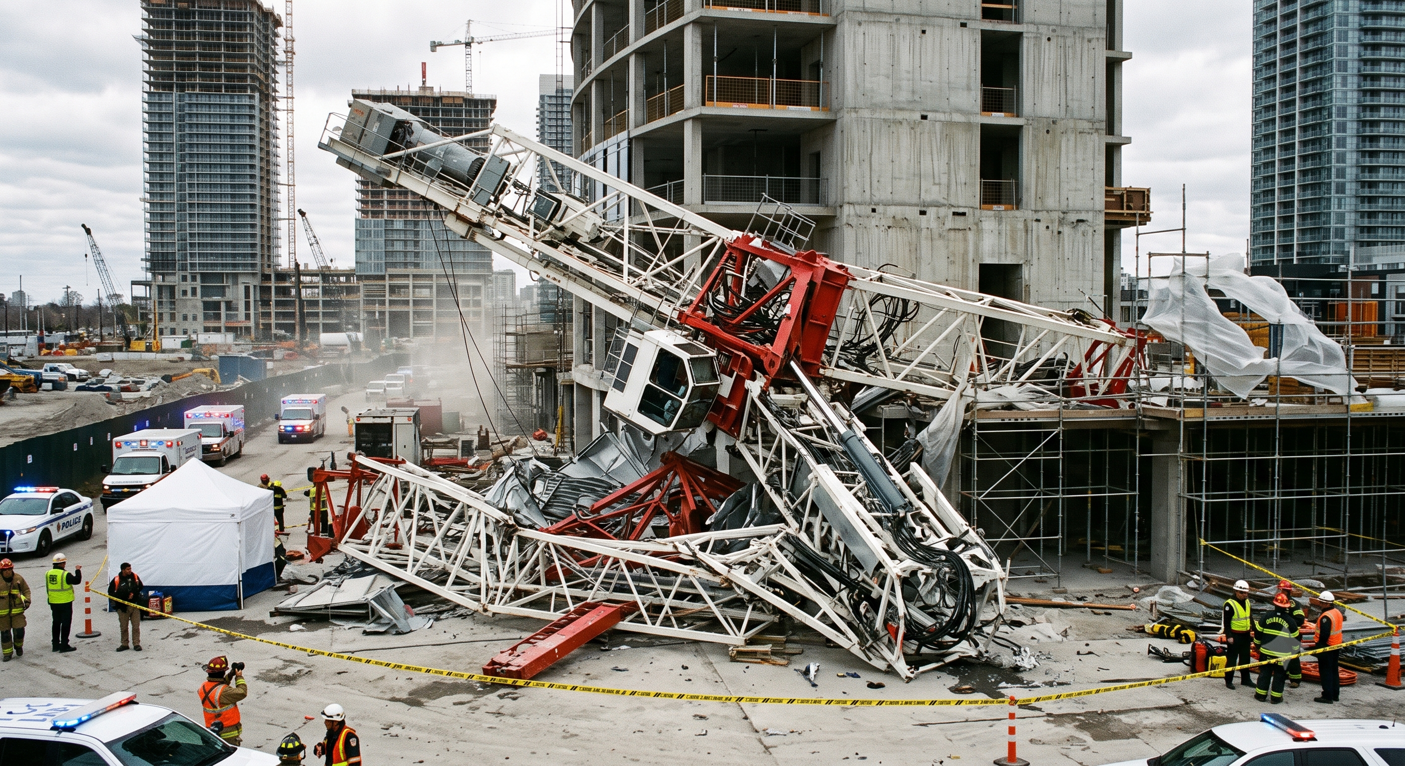
Important: The following scenario is hypothetical. It is provided for JSA discussion and must not be represented as an actual OSHA investigation, citation, or accident record.
A top-climbing crew begins a planned mast insertion while the upper crane is separated from its normal fully connected condition. Wind remains below the project team's informal rule of thumb but exceeds the lower climbing limit stated in the manufacturer manual. The difference is missed because the permit records a generic numerical limit rather than the crane-model-specific value.
The trolley is near, but not at, the specified balance radius. The crew also assumes that the normal swing brake is sufficient, even though the manufacturer climbing procedure requires a separate positive restraint.
When a gust acts on the jib, the upper crane rotates and the climbing frame racks against the mast. A guide component binds, and only one load-transfer support seats correctly.
The crew changes hydraulic load without completing the required visual and physical verification. Eccentric loading increases, causing abnormal pressure and structural deformation. Personnel remain inside pinch zones because the command sequence and emergency-stop signal were not reviewed.
A dropped tool also enters the ground work area because the restricted zone was based on an arbitrary radius rather than the actual fall and collapse envelopes.
Barrier Analysis
| Failed Barrier | Why It Failed | Required Prevention |
|---|---|---|
| Manufacturer procedure | Generic site rules replaced model-specific instructions. | Record the manual number, revision, prohibitions, wind limit, balance data, restraint method, and stroke sequence in the permit. |
| A/D direction | Roles and stop-work signals were unclear. | Conduct a documented pre-task briefing and use one command authority. |
| Wind control | A made-up universal threshold was used. | Use the manufacturer limit or qualified-person determination required by §1926.1435(b)(4)(iii). |
| Balance and restraint | Position and restraint were assumed rather than physically verified. | Require a signed hold point before releasing structural connections. |
| Load-transfer verification | Hydraulic movement continued without positive support confirmation. | Require verification at every stroke before changing the load path. |
| Restricted area | A fixed radius did not cover the credible exposure area. | Base barricades on the actual fall, swing, and collapse envelopes. |
5. Conditional decisions and common errors
| Condition | Action | Evidence | Proceed when |
|---|---|---|---|
| Before opening | Balance, restraint and temporary support not confirmed | Keep connections intact; resolve missing evidence | All three verified |
| Every stroke | A support is only partly seated | Stop; use the model contingency | All required seats confirmed |
| Section transfer | Section aligned but not positively retained | Keep approved handling support in place | Restraint accepted |
| Interrupted climb | Weather recovers but defect remains | Keep work suspended; inspect the affected state | Cause and hold points closed |
| Return to service | Bolts complete but tests pending | Retain operational prohibition | Required inspections accepted |
Similar situations, different decisions
| Comparison | Situation A | Situation B |
|---|---|---|
| Balance | A level reading alone | Model method, load/radius, orientation and checker recorded |
| Support | Pressure appears steady | Each specified bearing and retainer checked at the named stroke |
| Connection | Paint mark present | Hardware, method, tool and acceptance result traceable |
| Handover | Crew says complete | Final configuration, tests, defects and release authority recorded |
Use the exact manufacturer climbing manual, approved configuration and jurisdiction-specific engineering documents. No actual model manual or site calculations were supplied. Do not infer wind limits, torque, support capacity, free-standing height or a pin-removal sequence from this guide. A support may carry hydraulic load during a prescribed stroke; mechanical transfer is required at the stages specified for that system.
5.1 Manufacturer Procedure and Engineering Control
The permit must identify the exact procedure used for the crane configuration. Do not combine instructions from different crane models, climbing frames, or manual revisions.
Where an employer-developed procedure is permitted, it must satisfy the applicable OSHA requirements and receive the qualified-person or registered-Professional-Engineer involvement required by Subpart CC.
For internal climbing and tied tower configurations, obtain the required RPE verification for forces imposed on the host structure through braces, brace anchorages, and supporting floors.
The calculation package and approved climbing sequence must correspond with actual field conditions.
5.2 Wind and Weather Control
Federal OSHA's tower-crane rule uses a manufacturer-based limit, not a universal 20 mph limit.
The permit must state:
- Maximum allowable wind speed
- Whether the limit refers to sustained wind, peak gust, or another defined measurement
- Wind-measuring instrument and location
- Warning level below the stop limit
- Monitoring and recording interval
- Lightning, precipitation, icing, visibility, and temperature restrictions
- Procedure for safely securing the crane if conditions deteriorate mid-climb
- Required inspections and approvals before restarting
If the manufacturer provides no wind limit, a qualified person must determine and document the allowable speed under §1926.1435(b)(4)(iii).
5.3 Balance, Counterweight, and Slew Restraint
Counterweight and ballast amount and position must comply with §1926.1435(b)(8).
The following information must come from the manufacturer climbing procedure or approved engineered procedure:
- Trolley position
- Balance load
- Jib orientation
- Acceptable connection gap
- Level and plumb criteria
- Method of preventing unintended rotation
- Required monitoring instruments
- Conditions for releasing structural connections
Do not state that a “mechanical slewing lock pin” is required unless the specific crane has that device and the controlling procedure requires its use.
The permit must identify the actual restraint installed on the crane, such as a slew brake, locking pin, locking bar, or other engineered device.
5.4 Hydraulic Climbing System and Load Transfer
Verify the safety devices required by §1926.1435(d), including integrally mounted check valves on load-supporting hydraulic cylinders and the hydraulic pressure-limiting device.
These devices do not replace the prescribed climbing sequence or positive load-transfer system.
Depending on the crane design, the load-transfer components may include:
- Climbing dogs
- Pawls
- Yokes
- Shoes
- Pins
- Wedges
- Support beams
- Proprietary manufacturer assemblies
At every change in load path:
- Stop movement.
- Confirm alignment.
- Verify specified seating or engagement.
- Confirm required retainers and positive locks.
- Keep personnel clear of the movement path.
- Obtain the A/D Director's hold-point release.
5.5 Mast Sections, Pins, and Bolted Connections
Use components and connecting hardware accepted by the manufacturer or approved engineering procedure.
The connection specification must address:
- Part number, grade, dimensions, and compatibility
- New-versus-reusable criteria
- Rejection criteria for corrosion, wear, deformation, thread damage, or uncertain identity
- Lubrication and coating condition
- Tightening or tensioning sequence
- Required torque, tension, turn-of-nut, pin engagement, or other acceptance method
- Tool inspection and calibration requirements
- Independent inspection and documentation
Matchmarking can provide a useful visual completion and movement indicator when required by the procedure. A paint mark alone does not prove that the correct bolt tension was achieved.
5.6 Fall Protection, Falling Objects, and Rescue
Apply §1926.1423 and all other applicable construction fall-protection requirements to each work position and access route.
The fall-protection plan must address:
- Protected access to the tower and climbing frame
- Guardrails, personal fall arrest, travel restraint, or positioning systems
- Anchorage and connector compatibility
- Swing-fall, free-fall, and sharp-edge hazards
- Tool and small-part retention
- Fall-zone control under §1926.1425
- Prompt rescue after a fall
- Recovery of a suspended worker from the tower or climbing frame
Do not assume that every work position can safely use the same lanyard, self-retracting lifeline, or anchorage arrangement.
5.7 Restricted-Access Area and Fall Zone
Do not use a generic 35-foot radius unless a site-specific assessment establishes that distance as adequate.
The restricted-area drawing must consider:
- Tower and climbing-frame footprint
- Mast-section transfer route
- Suspended-load fall zone
- Jib and counter-jib movement
- Potential wind-induced drift
- Dropped-tool and dropped-component paths
- Assisting-crane setup and load path
- Potential collapse direction
- Adjacent occupied structures
- Entrances, roads, and public areas
- Simultaneous construction activities
Use barricades, warning signs, and trained access-control personnel appropriate to the exposure.
“Spotter,” “signal person,” “barricade attendant,” or “access-control attendant” is normally clearer U.S. terminology than “watchman.” Only personnel performing signaling duties should be identified as signal persons.
Technical failure review
| Job stage | Hazards and effects | Failure factors | Technical and procedural controls | Site verification |
|---|---|---|---|---|
| Plan | 1. Wrong model2. Tie failure3. Crew conflict | 1. Wrong revision2. Unchecked support3. Unassigned command | 1. Match crane and frame2. Approve temporary states3. Assign one director | 1. Manual revision2. Tie design3. Crew authority |
| Weather | 1. Wind torsion2. Falling objects3. Collision | 1. Ground-only reading2. Open boundary3. No securing plan | 1. Set model wind limits2. Control full exposure zone3. Plan safe interruption | 1. Wind basis2. Boundary map3. Securing method |
| Inspect | 1. Hydraulic drift2. Guide failure3. Falls | 1. Leaking circuit2. Worn support3. Unsafe platform | 1. Inspect valves and hoses2. Check guides and supports3. Verify access and rescue | 1. Test record2. Support condition3. Rescue readiness |
| Balance | 1. Eccentric moment2. Unwanted slew3. Support overload | 1. Wrong radius2. Wrong ballast3. Premature release | 1. Set prescribed balance2. Verify slew restraint3. Hold before opening mast | 1. Load and radius2. Restraint state3. Temporary load path |
| Each stroke | 1. Support slip2. Ram side load3. Crushing | 1. Partial seating2. Conflicting signals3. Ignored binding | 1. Follow model sequence2. Check every load transfer3. Stop on abnormal motion | 1. All support seats2. Stroke and pressure3. People clear |
| Insert | 1. Dropped section2. Transfer runaway3. Trapped hands | 1. Wrong section2. Missing end stop3. Forced alignment | 1. Match section and rigging2. Secure before detaching3. Use approved alignment | 1. Section identity2. Stops and retainers3. Temporary restraint |
| Connect | 1. Mast separation2. Fastener damage3. Dropped tools | 1. Wrong hardware2. Uncontrolled tightening3. Matchmarks only | 1. Apply specified method2. Check every connection3. Hold before load change | 1. Part and reuse rule2. Tool and results3. Independent check |
| Release | 1. Premature use2. Loose components3. Limit failure | 1. Open defects2. Old configuration3. Verbal handover | 1. Restore operating state2. Complete required tests3. Authorise return to use | 1. Final configuration2. Defect closure3. Release record |
6. Roles and responsibilities
| Role | Minimum Responsibility |
|---|---|
| Employer / Controlling Contractor | Coordinate employers and site access; verify applicable federal, State Plan, local, owner, and contractual requirements; prevent conflicting operations; provide emergency resources. |
| Project Superintendent | Confirm the approved schedule, site conditions, restricted area, assisting equipment, public protection, and employer high-risk work permit. |
| A/D Director | Direct the climbing operation; understand the selected procedure; address required hazards; brief the crew; control hold points; stop work when limits or procedures are not met. |
| Registered Professional Engineer | Perform or verify engineering work required for structural supports, host structure, braces, anchorages, supporting floors, or employer-developed procedures. |
| Qualified Person | Perform assigned technical determinations and inspections within the person's demonstrated knowledge, training, and experience. |
| Competent Person | Identify existing and predictable hazards within the assigned scope and take prompt corrective action. |
| Tower Crane Operator | Operate only on the A/D Director's command during climbing; monitor instruments; report abnormal conditions; stop for communication loss or unsafe movement. |
| Qualified Rigger | Inspect and select rigging; rig mast sections and other components; control load stability; prevent unintentional displacement. |
| Signal Person | Use the agreed signaling method; maintain communication with the operator; stop movement if communication is lost. |
| Climbing Crew | Follow the manufacturer sequence and briefing; remain clear of prohibited zones; complete assigned verification; report abnormal conditions. |
| Access-Control Attendant | Maintain barricades; prevent unauthorized entry; coordinate crossings only when the operation is stopped and access is authorized. |
| Rescue Team | Maintain site-specific elevated-rescue capability, equipment, communication, and access throughout the operation. |
Supervision, records, handover
| Job stage | Technical and procedural controls | Site verification |
|---|---|---|
| Work package | 1. Index the approved documents2. Name competent roles3. Brief rescue and stop rules | 1. Manual revision2. Tie design3. Crew authority |
| External controls | 1. Assign wind and access watch2. Record current conditions3. Confirm one radio channel | 1. Wind basis2. Boundary map3. Securing method |
| Witness inspection | 1. Witness critical inspections2. Quarantine rejected parts3. Close defects before release | 1. Test record2. Support condition3. Rescue readiness |
| Balance release | 1. Witness balance and restraint2. Record independent check3. Control connection release | 1. Load and radius2. Restraint state3. Temporary load path |
| Stroke command | 1. Log every stroke and support2. Confirm commands received3. Suspend on any uncertainty | 1. All support seats2. Stroke and pressure3. People clear |
| Final acceptance | 1. Separate installer and checker2. Accept tests and defect closure3. Record operating release | 1. Final configuration2. Defect closure3. Release record |
7. Hold points and record comparison
| Hold point | Evidence before release | Confirmation / approval |
|---|---|---|
| Start | Use the exact manufacturer climbing manual, approved configuration and jurisdiction-specific engineering documents. No actual model manual or site calculations were supplied. Do not infer wind limits, torque, support capacity, free-standing height or a pin-removal sequence from this guide. A support may carry hydraulic load during a prescribed stroke; mechanical transfer is required at the stages specified for that system. | |
| HP-1 Balance | Does the counterweight and ballast match the approved configuration?; Are the balance load, trolley radius, and jib orientation correct?; Is the specified slew-restraint method fully applied?; Are level, plumb, connection-gap, and guide-clearance criteria acceptable? | |
| HP-2 Each stroke | Are the load-transfer supports fully seated and retained as specified?; Are hydraulic pressure, cylinder position, and guide alignment normal?; Are personnel clear of shear, pinch, and potential movement zones?; Has the A/D Director released the hold point for this stroke? | |
| HP-3 Connect | Does every bolt, nut, pin, washer, and retainer meet the specification?; Is required tooling identified, inspected, and within its calibration period?; Are torque, tension, pin engagement, or other acceptance results recorded?; Has an independent qualified checker accepted every required connection? | |
| HP-4 Release | Does the final crane configuration match the approved plan?; Are required inspections, tests, and plumb checks complete?; Have all personnel, tools, and temporary components been accounted for?; Has the A/D Director and responsible site representative authorized return to service? |
Complete after actual checks. Recheck after changes, defects or shift handover.
Record comparison examples
The boxes are static record prompts, not interactive or saved approvals. A tick does not establish suitability or permission to restart. Record the evidence, person, time and unresolved issues; retain the change history.
| Record type | Insufficient record | Record checklist |
|---|---|---|
| Weather | Verbal or undated confirmation only | □ Wind basis□ Boundary map□ Securing method□ Manual section, time and checker |
| Balance | Verbal or undated confirmation only | □ Load and radius□ Restraint state□ Temporary load path□ Manual section, time and checker |
| Each stroke | Verbal or undated confirmation only | □ All support seats□ Stroke and pressure□ People clear□ Manual section, time and checker |
| Connect | Verbal or undated confirmation only | □ Part and reuse rule□ Tool and results□ Independent check□ Manual section, time and checker |
8. Site checklist and emergency response
| Check item | Result | Person / action |
|---|---|---|
| □ Plan: Does the manual number and revision match the installed crane? | ||
| □ Weather: Is the controlling wind limit and measurement basis recorded? | ||
| □ Inspect: Has the required component inspection been documented? | ||
| □ Balance: Does the counterweight and ballast match the approved configuration? | ||
| □ Each stroke: Are the load-transfer supports fully seated and retained as specified? | ||
| □ Insert: Are the mast-section ID, weight, lifting points, and compatibility verified? | ||
| □ Connect: Does every bolt, nut, pin, washer, and retainer meet the specification? | ||
| □ Release: Does the final crane configuration match the approved plan? | ||
| □ Release / handover authority |
Stop work
Stop for missing support confirmation, abnormal pressure or movement, guide binding, loss of communication, weather outside the approved envelope, an incomplete connection or entry into the exposure zone. Stop progressing the sequence; keep the system in its prescribed holding condition.
Emergency response
Do not automatically depressurise, reverse the ram, lower onto the nearest support or release a slew restraint. These actions can remove the current load path. Apply the manufacturer contingency for the actual stage, secure the area and obtain the responsible technical direction. Rescue must not depend on moving an unstable crane. Restart requires cause identification, correction, reinspection and repeat release of the affected hold points.
9. Sources and review limits
2026-10-08
United States: federal OSHA Subpart CC is the baseline; verify State Plan and local duties. Under 1926.1435, climbing invokes 1403-1406, supports need the specified design and the host structure requires RPE verification. The original wind-indicator reference 1926.1435(e)(5)(v) is corrected to (e)(6)(v); (e)(5)(v) concerns load moment limiting. ASME full text was not reviewed.
| Source | Scope and limitations |
|---|---|
| OSHA - 29 CFR 1926.1435 | Reviewed climbing, wind, supports, ballast, hydraulic safety devices, wind-speed indication and inspection provisions. No universal wind limit or permit form is inferred. |
Use the exact manufacturer climbing manual, approved configuration and jurisdiction-specific engineering documents. No actual model manual or site calculations were supplied. Do not infer wind limits, torque, support capacity, free-standing height or a pin-removal sequence from this guide. A support may carry hydraulic load during a prescribed stroke; mechanical transfer is required at the stages specified for that system.
10. PDF guidance and FAQ
PDF A covers basic task controls; B focuses on technical failures; C covers supervision, records and handover. The article has eight stages with four items per main cell; each PDF has six key stages with three items per main cell. P/S/R/A, measurements, confirmations and signatures remain blank for actual site assessment.
jsa-crane-telescoping
Does steady pressure prove safe support?
No. Identify the current load path and verify all supports and retainers required by the model before the next transfer. Pressure alone cannot confirm seating.
Can climbing resume as soon as wind drops?
No. Check the securing state, forecast, defects and changed configuration; repeat affected hold points before authorised restart.
Does a paint mark prove bolt preload?
No. Use the specified installation and verification method with traceable tooling and recorded results. Matchmarks are supplementary.
Are A/B/C separate operating procedures?
No. A summarises field controls, B examines mechanical failures, and C organises supervision and evidence. Read them with the full eight-stage body and actual manufacturer procedure.
Has a professional verified or approved this document?
No. Public sources and editorial, layout and consistency checks were reviewed using AI. No site inspection or professional technical approval has been performed. Obtain appropriate professional review before use.
11. Revision history and authorship
This is reference content written and revised with AI. It has not been verified or approved by a professional. Review by a suitably qualified professional and site authorisation are required before use.
Original body and three A/B/C downloads retained in recovery records; no numeric revision identified in their text or metadata. A/B/C describe perspectives, not chronological revisions. This dated revision is v1.1; it is an editorial revision without professional technical approval.
| Date | Version | Change | Review status |
|---|---|---|---|
| 2026-09-16 | A/B/C | Original preserved | No professional approval |
| 2026-10-08 | v1.1 | Decisions, records, JSA and PDFs revised | No professional approval |
Preserved the useful original controls and training scenario. Consolidated the original stages into eight without treating a grouped row as a machine operating sequence. Added explicit interruption/restart decisions, record comparisons and model-specific load-path limits. Original source links remain traceable in the recovery record; only the current review scope listed here is claimed. Corrected the wind-speed indicator cross-reference to 1926.1435(e)(6)(v).