A jib can be within the assist crane capacity and still fail when a connection changes its support path. This reference follows component identification, temporary support, connection transfer, ballast configuration and controlled dismantling. Its numbered stages are assessment checkpoints, not a manufacturer erection sequence: ballast changes belong at the exact positions required by the actual manual.
Before any pin moves, establish what will support every affected component
This is reference content written and revised with AI. It has not been verified or approved by a professional. Review by a suitably qualified professional and site authorisation are required before use.
Stop work
Stop for an unidentified component, changed geometry, binding pin, unexpected movement, unknown support load, lost communication, unauthorised entry or weather outside the planned conditions. Hold the configuration in its specified safe state; do not increase pulling or hammering force to overcome resistance.
1. Legal and technical scope
| Basis | Application limits |
|---|---|
| OSHA 1926.1435 | Official text reviewed for tower-crane scope, ballast, wind and erection inspection. |
| OSHA 1926.1404 | A/D direction, assist load verification, support, picks and components. |
| OSHA 1926.1405 | Specific pin-removal prohibitions during dismantling. |
| Liebherr - Influence of wind | Manufacturer educational material on wind effects; not the operating or erection manual for the actual crane. No model-specific limit is transferred. |
United States: determine whether federal OSHA or a State Plan applies. Tower-crane work is covered by relevant Subpart CC provisions, including the specific erection/dismantling requirements. This reference is not a compliance certification.
1926.1435 links tower-crane erection/dismantling to 1926.1403–1406, and addresses stage-specific ballast, wind and erection inspections. Under 1926.1404, A/D direction requires the stated competent/qualified arrangements. Section 1926.1405 prohibits specified pin removals in loaded or unsupported conditions. Review each applicable condition; neither a 20 mph universal threshold nor a mandatory 75% limit is established by this review. ASME B30.3/B30.5 and ANSI full texts were not reviewed.
2. Scope and required inputs
Included scope
Assembly and dismantling of an identified tower-crane jib with an assist crane, planned access and a controlled landing area. Use the manual for the serial number, jib length, tower configuration, ballast and attachments actually present.
Separate review
Climbing, foundation design, improvised structural repair, tandem lifting and a change between hammerhead, flat-top or luffing-jib configurations require separate procedures. A crane assisting another crane does not by itself make the lift a tandem lift.
| Required input | What to verify |
|---|---|
| Configuration | Serial number, jib sections, trolleys, ropes, pendants where fitted, ballast schedule and approved manual revision. |
| Support | Each intermediate load path, component mass/centre of gravity, approved pick points and assist-crane load at every relevant radius. |
| Site | Bearing evidence, support reactions/mat design, clearances, exclusion boundary, access and rescue arrangement. |
| Release criteria | Named decision maker, connection/retainer checks, required measurements, wind conditions and inspection/test scope. |
No crane model, assembly manual, site bearing report or lift calculation was supplied. No lifting point, pin order, ballast amount, slew restraint or wind threshold is approved here. Obtain these inputs before work; a generic JSA cannot replace them.
3. Eight-stage JSA
| Job stage | Hazards and effects | Failure factors | Technical and procedural controls | Site verification | P | S | R | A |
|---|---|---|---|---|---|---|---|---|
| 1. Confirm sequence | 1. Jib collapse2. Rearward overturn3. Wrong component4. Unsafe restart | 1. Wrong manual2. Ballast mismatch3. Unknown attachment4. Unbriefed change | 1. Match configuration2. Map support states3. Verify ballast stages4. Brief hold points | 1. Manual revision2. Component list3. Ballast schedule4. Release roles | ||||
| 2. Set assist crane | 1. Crane overturn2. Load overload3. Boom collision4. Public struck | 1. Weak ground2. Wrong radius3. Hidden services4. Open lift path | 1. Verify support design2. Check chart and load3. Plan clearances4. Exclude work zone | 1. Support reactions2. Duty chart3. Route clearance4. Wind conditions | ||||
| 3. Build on supports | 1. Jib rolls2. Pin failure3. Hand trapping4. Pendant falls | 1. Wrong support point2. Damaged pin3. Hand in joint4. Loose attachment | 1. Use specified supports2. Inspect correct parts3. Use safe alignment4. Secure attachments | 1. Support locations2. Pins and retainers3. Tool method4. Part condition | ||||
| 4. Lift and connect | 1. Jib rotation2. Root crushing3. Worker fall4. Crane clash | 1. Wrong pick points2. Poor signal3. Unsafe access4. Unplanned path | 1. Use approved picks2. Coordinate signals3. Provide safe access4. Check swept path | 1. Pick layout2. Crew position3. Access and rescue4. Root connection | ||||
| 5. Transfer support | 1. Jib drops2. Pin release injury3. Rigging slips4. Tool strikes | 1. Load path incomplete2. Retainer missing3. Abrupt lowering4. Loose hardware | 1. Check full connection2. Fit specified locks3. Transfer as instructed4. Secure loose items | 1. Support state2. Connection locks3. Release decision4. People clear | ||||
| 6. Control ballast | 1. Backward collapse2. Block drops3. Tray damage4. Unexpected slew | 1. Wrong stage mass2. Damaged lifting point3. Impact landing4. Wrong restraint | 1. Follow stage schedule2. Inspect lifting points3. Seat and secure blocks4. Use specified restraint | 1. Block IDs and mass2. Stage position3. Block retention4. Slew arrangement | ||||
| 7. Dismantle safely | 1. Unsupported jib2. Pin ejects3. Section rolls4. Crew struck | 1. Wrong removal order2. Bound connection3. Poor landing support4. Crew under section | 1. Use removal procedure2. Confirm support first3. Prepare landing stands4. Keep people clear | 1. Removal stage2. Pin release state3. Landing supports4. Section secured | ||||
| 8. Inspect and hand over | 1. Unaccepted crane use2. Hidden defect3. Dropped remnant4. Unsafe next shift | 1. Test omitted2. Damage unreported3. Loose shipping part4. Limits not passed | 1. Arrange required tests2. Record defects3. Secure stored parts4. Transfer restrictions | 1. Inspection record2. Defect disposition3. Storage condition4. Receiving authority |
PDF A covers basic task controls; B focuses on technical failures; C covers supervision, records and handover. The article has eight stages with four items per main cell; each PDF has six key stages with three items per main cell. P/S/R/A, measurements, confirmations and signatures remain blank for actual site assessment.
4. Fictional scenario and failure mechanisms
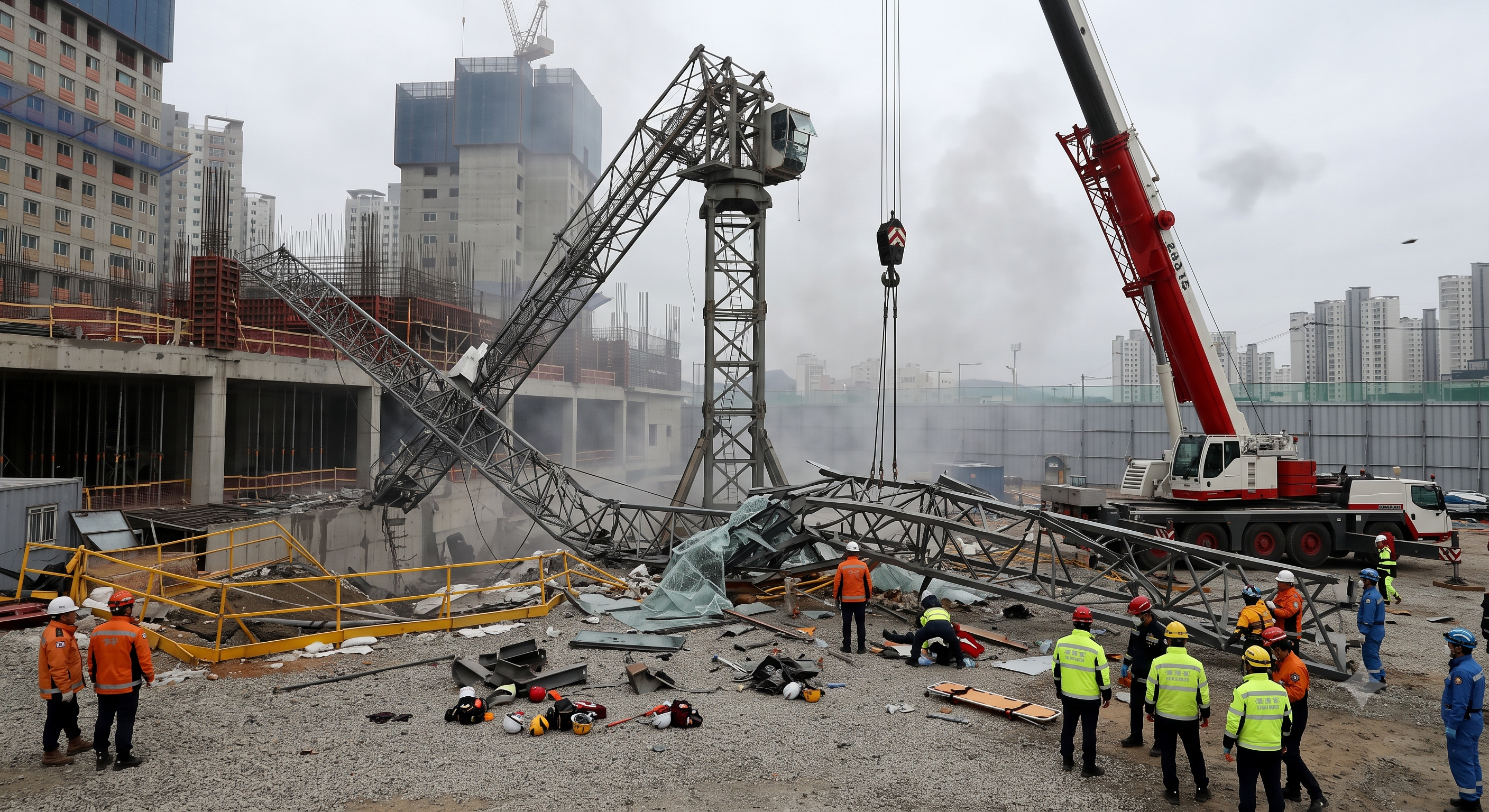
The original educational image is retained. It is not evidence of an actual incident or site suitability.
The scenario and record comparisons are fictional teaching examples, not records of real incidents, measurements, inspections, signatures or approvals.
| Item | Fictional scenario |
|---|---|
| Initial situation | A fictitious crew prepares to lower a pendant-supported jib. The drawing at the workface omits an attachment added since the lift plan was prepared. |
| Changed condition | The assist crane takes load at the old pick arrangement. A connection remains bound; the reading at the hook alone does not establish the forces at that joint. |
| Failure path | Continuing to drive the pin could release stored force and shift the component into an unsupported condition. This is a possible failure pathway, not an account of an investigated accident. |
| Possible outcome | The supervisor stops pin work, maintains the prescribed support and reconciles configuration, pick points and the load-transfer procedure with the responsible technical authority. |
| Prevention barrier | Work resumes only after revised instructions are briefed and the specified support, access, weather and release checks are actually recorded. No injury totals or official findings are asserted. |
Failure mechanisms
Support transition: the service arrangement and the erection arrangement carry loads differently. Pendant-supported, flat-top and luffing systems cannot be treated as the same prestressed truss. Each temporary state must have a defined stable support path.
Pin resistance: a pin may bind from force, misalignment, deformation or corrosion. Free motion is not by itself proof of zero load, and a load-cell reading is not a complete structural analysis. Follow the approved support and extraction method; protect against sudden release.
Rigging geometry: the number and spacing of picks must protect the actual lattice members and control centre of gravity. Four sling legs do not guarantee equal sharing or eliminate torsion. Do not attach to a convenient chord without an approved pick arrangement.
Ballast and wind: both forward and backward stability change as components are added or removed. Retain the specified ballast and restraint at every state. Assembly limits, operating limits and out-of-service arrangements can differ; do not assume one slew-lock instruction applies to all three.
Decision sequence
| Decision stage | What to verify |
|---|---|
| Known facts | Match the actual model and attachments to the current procedure; resolve missing component data before assembling the lift. |
| Unresolved matters | Check both the tower-crane intermediate state and assist-crane configuration, radius, support and deductions. |
| Reason to hold | Establish access, rescue, communications and exclusion zones before anyone enters the connection work position. |
| Required evidence | At each connection transfer, verify the specified support and retainers; permit crane movement only after the agreed clear-person signal. |
| Restart decision | For dismantling, use the specific removal sequence, then land and secure sections, inspect damage and record the final status. |
5. Conditional decisions and common errors
| Condition | Action | Evidence | Proceed when |
|---|---|---|---|
| Model mismatch | Hold and reconcile configuration | Matching manual, parts and lift data | Configuration matches |
| Support transfer | Retain support until checks pass | Connections, retainers and support state | Support and locks checked |
| Bound pin | Stop and resolve the cause | Approved support and extraction method | Release condition proven |
| Completion | Keep use restricted pending checks | Required inspection and defect records | Handover evidence complete |
Similar situations, different decisions
The scenario and record comparisons are fictional teaching examples, not records of real incidents, measurements, inspections, signatures or approvals.
| Comparison | Situation A | Situation B |
|---|---|---|
| Pin binds | Force it out because the assist crane shows a load | Stop, retain support and resolve joint forces/alignment under the approved procedure |
| Ballast change | Treat dismantling as the reverse of a generic table | Check the exact intermediate ballast and component sequence for this configuration |
| Wind change | Use yesterday’s ground reading or a universal limit | Use the specified measurement location, gust criteria and securing action for this stage |
6. Roles and responsibilities
| Role | Responsibility |
|---|---|
| Planner / technical authority | Establish the crane-specific sequence and support conditions, including variations that require engineering review. |
| Assembly supervisor | Brief roles and hold points; control access and give the documented connection-release decision after actual checks. |
| Assist-crane operator | Confirm configuration and capacity throughout the lift; stop on loss of the agreed signal or unexpected load/motion. |
| Erection crew / signal person | Inspect assigned components, maintain safe positions and communicate one coordinated movement instruction; anyone may call an emergency stop. |
| Inspector / site manager | Arrange the required erection inspection and tests, record restrictions and prevent use before acceptance. |
Supervision, records, handover
| Job stage | Technical and procedural controls | Site verification |
|---|---|---|
| Approve sequence | 1. Reconcile model2. Accept stage plan3. Plan rescue | 1. Manual issue2. Load data3. Rescue plan |
| Accept setup | 1. Check support proof2. Verify duty chart3. Secure perimeter | 1. Bearing evidence2. Crane setup3. Exclusion plan |
| Release connection | 1. Check load path2. Verify locks3. Control release | 1. Connection record2. Support state3. Release person |
| Confirm ballast | 1. Check stage mass2. Accept block condition3. Verify restraint | 1. Block list2. Stage record3. Slew status |
| Approve dismantling | 1. Brief removal order2. Stop on binding3. Confirm landing | 1. Procedure issue2. Hold-point record3. Support layout |
| Close and transfer | 1. Confirm inspection2. Resolve defects3. Record handover | 1. Test record2. Defect status3. Receiving person |
7. Hold points and record comparison
| Hold point | Evidence before release | Confirmation / approval |
|---|---|---|
| Start | Assembly and dismantling of an identified tower-crane jib with an assist crane, planned access and a controlled landing area. Use the manual for the serial number, jib length, tower configuration, ballast and attachments actually present. | |
| HP-1 Lift and connect | Pick layout · Crew position · Access and rescue · Root connection | |
| HP-2 Transfer support | Support state · Connection locks · Release decision · People clear | |
| HP-3 Dismantle safely | Removal stage · Pin release state · Landing supports · Section secured | |
| HP-4 Inspect and hand over | Inspection record · Defect disposition · Storage condition · Receiving authority |
Complete after actual checks. Recheck after changes, defects or shift handover.
Record comparison examples
The scenario and record comparisons are fictional teaching examples, not records of real incidents, measurements, inspections, signatures or approvals.
The boxes are static record prompts, not interactive or saved approvals. A tick does not establish suitability or permission to restart. Record the evidence, person, time and unresolved issues; retain the change history.
| Record type | Insufficient record | Record checklist |
|---|---|---|
| Configuration | Everything ready | □ Manual revision□ Component IDs□ Jib length□ Ballast stage |
| Transfer | Crane carrying it | □ Pick arrangement□ Connection locks□ Support state□ Release authority |
| Change | Nothing changed | □ Changed condition□ Technical disposition□ Updated briefing□ Restart decision |
| Handover | Job finished | □ Inspection scope□ Open defects□ Operating restrictions□ Receiving person |
8. Site checklist and emergency response
| Check item | Result | Person / action |
|---|---|---|
| □ Confirm sequence: Manual revision | ||
| □ Set assist crane: Support reactions | ||
| □ Build on supports: Support locations | ||
| □ Lift and connect: Pick layout | ||
| □ Transfer support: Support state | ||
| □ Control ballast: Block IDs and mass | ||
| □ Dismantle safely: Removal stage | ||
| □ Inspect and hand over: Inspection record | ||
| □ Release / handover authority |
Stop work
Stop for an unidentified component, changed geometry, binding pin, unexpected movement, unknown support load, lost communication, unauthorised entry or weather outside the planned conditions. Hold the configuration in its specified safe state; do not increase pulling or hammering force to overcome resistance.
Emergency response
On unplanned motion, alert the operator and supervisor, keep everyone outside the drop/crush area and use the predetermined securing and rescue plan. Do not approach a suspended or partly supported jib, remove more pins or improvise a rescue from the structure.
9. Sources and review limits
2026-10-08
| Source | Scope and limitations |
|---|---|
| OSHA 1926.1435 | Official text reviewed for tower-crane scope, ballast, wind and erection inspection. |
| OSHA 1926.1404 | A/D direction, assist load verification, support, picks and components. |
| OSHA 1926.1405 | Specific pin-removal prohibitions during dismantling. |
| Liebherr - Influence of wind | Manufacturer educational material on wind effects; not the operating or erection manual for the actual crane. No model-specific limit is transferred. |
This is reference content written and revised with AI. It has not been verified or approved by a professional. Review by a suitably qualified professional and site authorisation are required before use.
10. PDF guidance and FAQ
PDF A covers basic task controls; B focuses on technical failures; C covers supervision, records and handover. The article has eight stages with four items per main cell; each PDF has six key stages with three items per main cell. P/S/R/A, measurements, confirmations and signatures remain blank for actual site assessment.
Content group ID
jsa-crane-jib
Is 75% utilisation a universal legal limit?
No. Verify the actual chart, load deductions and planned safety margin. A project rule may impose an additional limit, but this reference does not establish a universal 75% cap.
Does every jib need four pick points and pendants?
No. Use the actual crane model and approved lifting arrangement. Flat-top and other configurations can have different support systems.
Can a bound pin be removed with a stronger tool?
Stop first. Resolve load, alignment and component condition using the approved procedure; a stronger tool does not establish that removal is safe.
Can the same wind and slew-lock rule be used for every stage?
No. Erection, dismantling, operation and out-of-service conditions may have different manufacturer requirements. Record the applicable state.
Has a professional verified or approved this document?
No. Public sources and editorial, layout and consistency checks were reviewed using AI. No site inspection or professional technical approval has been performed. Obtain appropriate professional review before use.
11. Revision history and authorship
This is reference content written and revised with AI. It has not been verified or approved by a professional. Review by a suitably qualified professional and site authorisation are required before use.
| Date | Version | Change | Review status |
|---|---|---|---|
| 2026-09-16 | Original version unmarked | Original preserved | No professional approval |
| 2026-10-08 | 1.1 | Decisions, records, JSA and PDFs revised | No professional approval |
Retained assist-crane checks, stable ground assembly, correct connection hardware, protected access, load transfer and staged ballast control. Withdrawn universal 75% utilisation, fixed wind/buffer distances, four-point rigging, two taglines, steel-only supports and mandatory hydraulic extraction claims. Replaced the unsourced fatal-accident/investigation narrative with an explicitly fictional decision scenario. Removed claims of professional validation and guaranteed compliance; the original title remains for record continuity. 1926.1435 links tower-crane erection/dismantling to 1926.1403–1406, and addresses stage-specific ballast, wind and erection inspections. Under 1926.1404, A/D direction requires the stated competent/qualified arrangements. Section 1926.1405 prohibits specified pin removals in loaded or unsupported conditions. Review each applicable condition; neither a 20 mph universal threshold nor a mandatory 75% limit is established by this review. ASME B30.3/B30.5 and ANSI full texts were not reviewed.