Panels can be light yet create a large wind area. The load path changes during assembly; completed-tower strength cannot establish the stability of a partly connected module. Retain the specified braces and lifting support until the stage-specific release conditions are met.
This is reference content written and revised with AI. It has not been verified or approved by a professional. Review by a suitably qualified professional and site authorization are required before use.
Stop before starting
Stop for unverified module weight, foundation, anchors or bracing, weather outside the actual stage limits, unsecured panels, fan movement, lost fall protection or unassessed existing-water exposure.
1. Legal and technical scope
| Basis | Scope and limits |
|---|---|
| OSHA 1926.251 | Construction rigging inspection, identification and capacity within scope. |
| OSHA 1926.501 | Construction fall-protection requirements depend on the actual surface and activity. |
| OSHA 1910.147 | Covered general-industry maintenance only; control potential fan movement. |
| CDC cooling towers | Water management and cleaning/disinfection before commissioning; guidance, not a construction release. |
Construction lifting, rigging, fall protection and electrical work require their applicable Part 1926 controls. Crane coverage depends on the actual equipment and operation. For later covered general-industry servicing, 1910.147 includes stored mechanical energy. CDC water-management guidance is advisory public-health guidance, not an OSHA assembly permit. Verify the applicable State Plan and actual tower erection instructions.
2. Scope and required inputs
Included work
Lifting and joining cooling tower modules and panels, temporary bracing, foundation anchors, fan guards, piping support and handover to water-system commissioning.
Separate assessment
Walking on fragile panels or fan guards, improvised brace removal, fan access based only on power-off, chemical dosing and live operation are outside this assembly scope.
| Required input | Evidence to obtain |
|---|---|
| Plan assembly | Module and weight; Foundation and anchors; Stage weather limits; Exclusion layout |
| Arrange access | Platform and guards; Access and rescue; Bearing and reactions; Drop-zone boundary |
| Inspect components | Fan safe condition; Edge protection; Panel and joint damage; Water-system history |
| Trial lift | Balance and slings; Weather and rotation; Lifting-point capacity; Exclusion maintained |
No actual equipment model, SDS, site measurements, design calculations or authorization record was supplied. Product-specific limits and methods must be verified before use. Federal OSHA is a baseline within its scope; determine the applicable State Plan and local requirements. Manufacturer guidance is not government approval; an incorporated standard differs from voluntary guidance. No nationwide-compliance or expert-approval claim is made.
3. Eight-stage JSA
| Job stage | Hazards and effects | Failure factors | Technical and procedural controls | Site verification | P | S | R | A |
|---|---|---|---|---|---|---|---|---|
| 1. Plan assembly | 1. Module drop2. Foundation failure3. Wind overturn4. Adjacent strike | 1. Weight unknown2. Anchors unreviewed3. Stage wind ignored4. Work zones overlap | 1. Match lift units2. Review anchors and base3. Set stage weather limits4. Separate work zones | 1. Module and weight2. Foundation and anchors3. Stage weather limits4. Exclusion layout | ||||
| 2. Arrange access | 1. Fall from height2. Fragile panel fall3. Crane settlement4. Dropped tools | 1. Panel used as floor2. Access missing3. Bearing unverified4. People below | 1. Provide independent access2. Install fall safeguards3. Verify equipment support4. Exclude lower area | 1. Platform and guards2. Access and rescue3. Bearing and reactions4. Drop-zone boundary | ||||
| 3. Inspect components | 1. Fan movement2. Edge cuts3. Panel breakage4. Contaminated aerosol | 1. Power not isolated2. Sharp edges3. Damaged members4. Water history unknown | 1. Control fan movement2. Protect sharp handling3. Inspect members4. Assess old water system | 1. Fan safe condition2. Edge protection3. Panel and joint damage4. Water-system history | ||||
| 4. Trial lift | 1. Unbalanced load2. Wind rotation3. Rigging failure4. People struck | 1. Balance untested2. Sail area ignored3. Wrong lift point4. Boundary entered | 1. Check balance low2. Monitor wind and attitude3. Use approved lift points4. Keep zone clear | 1. Balance and slings2. Weather and rotation3. Lifting-point capacity4. Exclusion maintained | ||||
| 5. Join and brace | 1. Incomplete overturn2. Pinched hands3. Falling bolts4. Early release collapse | 1. Braces omitted2. Hand alignment3. Loose hardware4. Crane released early | 1. Fit planned braces2. Use alignment tools3. Secure small parts4. Verify before unhooking | 1. Braces and anchors2. Alignment clearance3. Tool retention4. Support release | ||||
| 6. Guard and connect | 1. Fan contact2. Nozzle damage3. Chemical exposure4. Water aerosol | 1. Guard absent2. Pipe forced to fit3. SDS missing4. Water plan absent | 1. Install fan guards2. Support pipes separately3. Separate dosing scope4. Assign water management | 1. Guard inspection2. Pipe loads and movement3. Chemical interface4. Water plan owner | ||||
| 7. Weather or defect hold | 1. Loose panel flight2. Joint failure3. Fan rotation4. Unsafe re-entry | 1. Parts unsecured2. Improvised repair3. Windmill ignored4. Access removed | 1. Secure unfinished parts2. Review repair method3. Prevent fan movement4. Maintain access guards | 1. Remaining members2. Repair acceptance3. Fan restraint4. Entry restrictions | ||||
| 8. Inspect and hand over | 1. Loose fan part2. Leak and slip3. Water exposure4. Unauthorized startup | 1. Joint check omitted2. Drain blocked3. Owner unknown4. Release assumed | 1. Inspect joints and guards2. Verify drainage3. Transfer water duties4. Separate startup approval | 1. Joint and guard record2. Drainage and cleanup3. Water-system recipient4. Startup restrictions |
P = likelihood; S = severity; R = risk under the site method; A = site-defined acceptance/authorization. These actual assessment cells are blank. A low score never overrides a missing safeguard or a legal or manufacturer restriction.
4. Fictional scenario and failure mechanisms
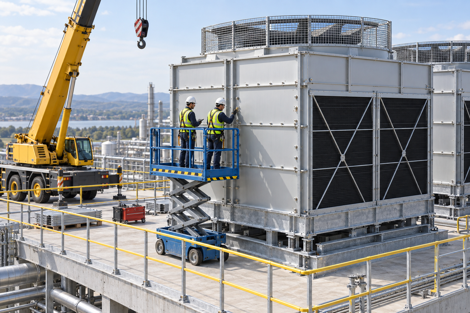
This illustration provides educational context. It is not an actual incident photograph or evidence of equipment suitability; any AI-generated depiction is illustrative only.
The scenario and record comparisons are fictional teaching examples, not records of real incidents, measurements, inspections, signatures or approvals.
| Stage | Fictional situation |
|---|---|
| Initial situation | A fictional crew attaches broad panels to a tower module. |
| Changed condition | Wind rises while only some joints are complete. |
| Failure path | The crew intends to release the crane using the finished structure capacity as its basis. |
| Possible outcome | The incomplete module may overturn or damage joints and strike people below. |
| Prevention barrier | Maintain support, reassess the current assembly stage and weather, and secure unfinished members before release. |
Failure mechanisms
Panels can be light yet create a large wind area. The load path changes during assembly; completed-tower strength cannot establish the stability of a partly connected module. Retain the specified braces and lifting support until the stage-specific release conditions are met.
Power-off does not prevent wind-driven fan motion. Before exposure, qualified personnel must establish the approved electrical and mechanical safe condition. Panels and guards are not working platforms unless specifically designed and accepted for that use.
Assembly inspection, fan-start authorization and water-system acceptance are separate decisions. Existing water, sludge and treatment chemicals require an exposure review; independent pipe support must prevent nozzle loading.
Work sequence: Plan assembly → Arrange access → Inspect components → Trial lift → Join and brace → Guard and connect → Weather or defect hold → Inspect and hand over. This is a teaching flow, not a device drawing or a complete operating procedure.
5. Conditional decisions and common errors
| Situation | Required action | Evidence | Proceed when |
|---|---|---|---|
| Wind increases | Hold exposed assembly | Stage limits and temporary supports | Stable stage verified |
| Unhook requested | Check release conditions | Anchors, braces and joints | Release authorized |
| Fan access needed | Control all movement | Electrical and mechanical isolation | Safe access verified |
| Assembly complete | Handover separate systems | Guards, pipe loads and water plan | Commissioning accepted |
Similar observations, different decisions
The scenario and record comparisons are fictional teaching examples, not records of real incidents, measurements, inspections, signatures or approvals.
| Observation | Insufficient conclusion | Required distinction |
|---|---|---|
| Bolts inserted | Some connection exists | Required stage connection still needed |
| Power off | Motor not driving | Wind can still turn fan |
| Tower assembled | Mechanical work advanced | Water and operational release separate |
6. Roles and responsibilities
| Role | Responsibility |
|---|---|
| Work supervisor | Confirm module and weight and the task scope, resources, interfaces and stop authority. |
| Qualified technical reviewer | Review platform and guards, model limits, compatibility and unresolved technical conditions within assigned competence. |
| Work crew | Apply the listed controls, report changes and stop when evidence or safeguards are missing. |
| Inspector / assessor | Record actual braces and anchors and other relevant checks; do not mark unverified conditions as accepted. |
| Handover authority | Reconcile joint and guard record, restrictions and outstanding actions before the next task. Role labels do not establish a legal credential. |
Supervision and handover focus
| Stage | Management action | Evidence |
|---|---|---|
| Plan assembly | 1. Record module and weight2. Record foundation and anchors3. Record stage weather limits | 1. Module and weight2. Foundation and anchors3. Stage weather limits |
| Arrange access | 1. Record platform and guards2. Record access and rescue3. Record bearing and reactions | 1. Platform and guards2. Access and rescue3. Bearing and reactions |
| Trial lift | 1. Record balance and slings2. Record weather and rotation3. Record lifting-point capacity | 1. Balance and slings2. Weather and rotation3. Lifting-point capacity |
| Join and brace | 1. Record braces and anchors2. Record alignment clearance3. Record tool retention | 1. Braces and anchors2. Alignment clearance3. Tool retention |
| Weather or defect hold | 1. Record remaining members2. Record repair acceptance3. Record fan restraint | 1. Remaining members2. Repair acceptance3. Fan restraint |
| Inspect and hand over | 1. Record joint and guard record2. Record drainage and cleanup3. Record water-system recipient | 1. Joint and guard record2. Drainage and cleanup3. Water-system recipient |
7. Hold points and record comparison
| Hold point | Evidence before release | Actual approval |
|---|---|---|
| HP-0 Scope | Lifting and joining cooling tower modules and panels, temporary bracing, foundation anchors, fan guards, piping support and handover to water-system commissioning. | |
| HP-1 Arrange access | Platform and guards; Access and rescue; Bearing and reactions; Drop-zone boundary | |
| HP-2 Trial lift | Balance and slings; Weather and rotation; Lifting-point capacity; Exclusion maintained | |
| HP-3 Weather or defect hold | Remaining members; Repair acceptance; Fan restraint; Entry restrictions | |
| HP-4 Inspect and hand over | Joint and guard record; Drainage and cleanup; Water-system recipient; Startup restrictions |
Hold points are internal project checks. They are not universal statutory permits and do not grant work permission. Reassess after defects, changed conditions and shift changes.
Record comparison
The scenario and record comparisons are fictional teaching examples, not records of real incidents, measurements, inspections, signatures or approvals.
The boxes are static record prompts, not interactive or saved approvals. A tick does not establish suitability or permission to restart. Record the evidence, person, time and unresolved issues; retain the change history.
| Record | Insufficient record | Record checklist |
|---|---|---|
| Plan assembly | Only marked “OK” | □ Module and weight□ Foundation and anchors□ Stage weather limits□ Exclusion layout |
| Trial lift | Only marked “OK” | □ Balance and slings□ Weather and rotation□ Lifting-point capacity□ Exclusion maintained |
| Weather or defect hold | Only marked “OK” | □ Remaining members□ Repair acceptance□ Fan restraint□ Entry restrictions |
| Inspect and hand over | Only marked “OK” | □ Joint and guard record□ Drainage and cleanup□ Water-system recipient□ Startup restrictions |
8. Site checklist and emergency response
| Site check | Actual result | Person / action |
|---|---|---|
| Plan assembly: Module and weight; Foundation and anchors; Stage weather limits; Exclusion layout | ||
| Arrange access: Platform and guards; Access and rescue; Bearing and reactions; Drop-zone boundary | ||
| Inspect components: Fan safe condition; Edge protection; Panel and joint damage; Water-system history | ||
| Trial lift: Balance and slings; Weather and rotation; Lifting-point capacity; Exclusion maintained | ||
| Join and brace: Braces and anchors; Alignment clearance; Tool retention; Support release | ||
| Guard and connect: Guard inspection; Pipe loads and movement; Chemical interface; Water plan owner | ||
| Weather or defect hold: Remaining members; Repair acceptance; Fan restraint; Entry restrictions | ||
| Inspect and hand over: Joint and guard record; Drainage and cleanup; Water-system recipient; Startup restrictions |
Stop work
Stop for unverified module weight, foundation, anchors or bracing, weather outside the actual stage limits, unsecured panels, fan movement, lost fall protection or unassessed existing-water exposure.
Emergency response
Stop lifting safely, clear the collapse/drop zone and activate the site rescue plan. Do not enter beneath an unstable module or rotating fan to recover tools. Qualified responders establish structural and energy control before rescue or recovery.
9. Sources and review limits
Public-source access/review: 2026-10-12.
| Official source | Reviewed scope and limits |
|---|---|
| OSHA 1926.251 | Construction rigging inspection, identification and capacity within scope. |
| OSHA 1926.501 | Construction fall-protection requirements depend on the actual surface and activity. |
| OSHA 1910.147 | Covered general-industry maintenance only; control potential fan movement. |
| CDC cooling towers | Water management and cleaning/disinfection before commissioning; guidance, not a construction release. |
No actual equipment model, SDS, site measurements, design calculations or authorization record was supplied. Product-specific limits and methods must be verified before use. Federal OSHA is a baseline within its scope; determine the applicable State Plan and local requirements. Manufacturer guidance is not government approval; an incorporated standard differs from voluntary guidance. No nationwide-compliance or expert-approval claim is made.
10. PDF guidance and FAQ
PDF A covers basic task controls; B focuses on technical failures; C covers supervision, records and handover. P/S/R/A, measurements, confirmations and signatures remain blank for actual site assessment.
PDFs are complementary six-stage extracts. Apply all eight body stages and the actual equipment/site procedure.
Can a fan guard serve as a platform?
Only if the actual design explicitly allows the intended loading; otherwise use independent access.
When can temporary braces be removed?
After the specified permanent load path and stage release conditions are verified by the responsible authority.
Does this worksheet authorize starting the tower?
No. Complete separate mechanical, electrical and water-management acceptance.
Has a professional verified or approved this document?
No. Public sources and editorial, layout and consistency checks were reviewed using AI. No site inspection or professional technical approval has been performed. Obtain appropriate professional review before use.
11. Revision history and authorship
This is reference content written and revised with AI. It has not been verified or approved by a professional. Review by a suitably qualified professional and site authorization are required before use.
| Date | Version | Change | Review status |
|---|---|---|---|
| 2026-10-12 | US 1.0 | New US edition from assigned Korean source; task decisions, records and PDFs localized. | AI editorial review; no professional technical approval |
Korean edition revision dates: 2026-03-02, 2026-09-19, 2026-09-26. US v1.0 adapts the earlier edition to United States requirements and terminology.
Site reviewers must add their actual qualifications, scope, date and approval only after the review occurs.