A level reading does not establish contact at every designed support. Pulling a raised foot down with an anchor can distort the base rather than correct the support defect.
This reference material was written and revised with AI. It has not been verified or approved by a professional. Review by a suitably qualified professional and required site approval are necessary before field use.
Stop before proceeding
Hold adjustment for unknown foundation, support points, energy boundaries or pressure state. Stop for jack descent, shim movement, base distortion, changed readings after tightening or pressure reaccumulation.
1. Legal and technical scope
Construction installation uses applicable 1926 rigging and electrical provisions; general-industry maintenance uses 1910.147 for hazardous energy and 1910.244 for relevant jacks. Determine the actual work classification. Manufacturer installation guidance supplies model-specific support, anchor, shim and alignment requirements.
Confirm whether federal OSHA or an OSHA-approved State Plan covers this employer and worksite; state requirements and public-sector coverage can differ. Apply the task-specific provisions and limitations identified above.
| Basis | Application |
|---|---|
| OSHA 29 CFR 1926.251 | Construction rigging identification, load limits and condition. |
| OSHA 29 CFR 1910.147 | Applicable general-industry servicing: isolate remote starts and stored pneumatic energy. |
| OSHA 29 CFR 1910.244 | Relevant jack capacity, inspection and support/blocking provisions in general industry. |
| Atlas Copco compressor-room placement | Public placement guidance reviewed for floor support, compressor-dependent foundations and access/ventilation. Not the installed model manual or a universal grout/anchor specification. |
| OSHA State Plans | Official overview of federal and State Plan jurisdiction and differing public-sector coverage, checked 2026-10-12. Individual state rules require a site-specific check. |
2. Scope and required inputs
Included scope
Receive and set a compressor package, isolate electrical and pressure sources, adjust specified supports and shims, verify fastening and pipe connection effects, and hand over the installed package.
Separate assessment
Adjustment while running, working beneath hydraulic support alone, unauthorized anchor or isolator changes, pressure testing and startup are excluded. Grouting is model- and design-dependent.
| Input | Evidence needed |
|---|---|
| Plan foundation | Model weight and center; Foundation evidence; Route clearances; Ventilation space. |
| Isolate energy | Power and remote list; Pressure reaccumulation; Surface and fluid state; Isolation verification. |
| Adjust shims | Lift and support state; Shim contact area; Level measurements; Operator signals. |
| Accept installation | Level and anchor data; Guard condition; Clean access; Commissioning restrictions. |
No site measurements, equipment manuals for the actual installation, inspection records or signed technical approvals were supplied. Confirm the applicable requirements and actual product instructions before use; record each criterion with its units, source and equipment or work-area ID.
3. Eight-stage JSA
| Job stage | Hazards and effects | Failure factors | Technical and procedural controls | Site verification | P | S | R | A |
|---|---|---|---|---|---|---|---|---|
| 1. Plan foundation | 1. Floor failure2. Package overturn3. Pipe interference4. Maintenance trapping | 1. Unknown package weight2. Weak foundation3. Narrow route4. No service space | 1. Match package drawing2. Verify support capacity3. Measure transport route4. Reserve service access | 1. Model weight and center2. Foundation evidence3. Route clearances4. Ventilation space | ||||
| 2. Unload and move | 1. Falling package2. Crane settlement3. Crushing in travel4. Unbalanced load | 1. Single-part lifting eye2. Poor ground support3. Confused signals4. No balance check | 1. Use assembly lift points2. Check crane capacity3. Exclude travel zone4. Check balance low | 1. Assembly lifting plan2. Radius and support3. Signals and barriers4. Sling contact | ||||
| 3. Isolate energy | 1. Unexpected motor start2. Pressure discharge3. Hot-oil contact4. Remote restart | 1. Remote signal missed2. Trapped pressure3. Hot surfaces4. Isolation untested | 1. Isolate all start sources2. Drain trapped sections3. Check oil temperature4. Verify safe energy state | 1. Power and remote list2. Pressure reaccumulation3. Surface and fluid state4. Isolation verification | ||||
| 4. Set and support | 1. Crushed fingers2. Base overturn3. Jack descent4. Isolator damage | 1. Hand positioning2. Wrong support point3. Hydraulic support only4. Wrong mount orientation | 1. Use positioning tools2. Use designated supports3. Provide mechanical support4. Match mount detail | 1. Pinch-zone clearance2. Support contact3. Blocking arrangement4. Mount type and direction | ||||
| 5. Adjust shims | 1. Ejected shim2. Twisted base3. Local overload4. Jack entrapment | 1. Excess lifting2. Unstable shim stack3. Wrong datum4. Conflicting controls | 1. Follow lift sequence2. Match shim specification3. Use consistent datum4. Assign one signal lead | 1. Lift and support state2. Shim contact area3. Level measurements4. Operator signals | ||||
| 6. Fasten and pipe | 1. Anchor failure2. Base distortion3. Nozzle overload4. Grout crushing | 1. Wrong torque2. No final recheck3. Forced pipe fit4. Early load transfer | 1. Use specified fastening2. Compare final level3. Support pipes separately4. Verify grout readiness | 1. Anchor record2. Level and contact3. Pipe strain check4. Curing evidence | ||||
| 7. Readjust safely | 1. Sudden package shift2. Pressure returns3. Falling tools4. Unauthorized start | 1. Fasteners released early2. Leaking isolation3. Loose shims4. Poor shift handoff | 1. Support before release2. Recheck stored pressure3. Control loose tooling4. Document changed setup | 1. Support transfer plan2. Zero-pressure state3. Tool inventory4. Lock transfer record | ||||
| 8. Accept installation | 1. Vibration damage2. Missing guard3. Oil-slip hazard4. Premature startup | 1. Final readings absent2. Door left open3. Leak uncorrected4. Release confused | 1. Transfer final readings2. Restore all guards3. Correct leaks and spills4. Separate startup release | 1. Level and anchor data2. Guard condition3. Clean access4. Commissioning restrictions |
P = likelihood; S = severity; R = risk under the site method; A = the site-defined acceptance/authorization decision. Complete only after actual assessment. Blank cells and checklist prompts are not completed inspections.
4. Fictional scenario and failure mechanisms
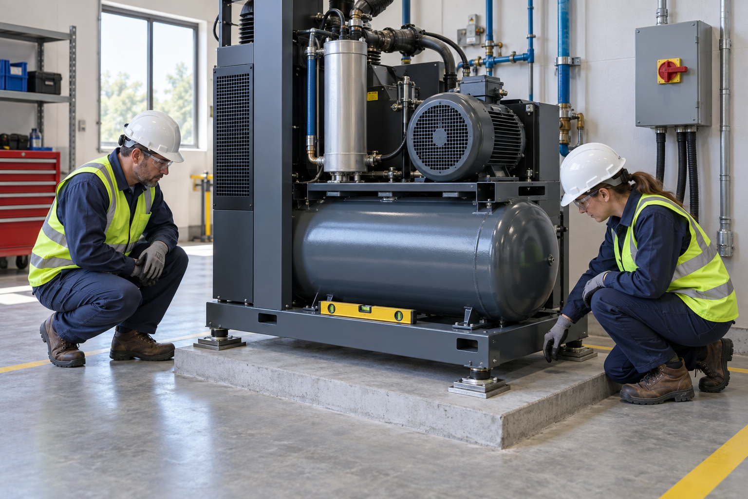
Retained AI-generated educational illustration from the source edition; not a real incident photograph, approved installation drawing or evidence of equipment suitability.
The scenario and record comparisons are fictional teaching examples, not records of real incidents, measurements, inspections, signatures or approvals.
| Item | Fictional scenario |
|---|---|
| Initial | The crew is leveling a compressor base. |
| Change | An anchor is tightened while one support foot remains clear of its bearing surface. |
| Failure | Fastener force is treated as proof of correct support contact. |
| Outcome | The base can distort and later pipe or rotating-equipment alignment can change. |
| Barrier | Stabilize the package, correct the support and shim arrangement, then compare final readings after fastening and pipe connection. |
Why the controls matter
A level reading does not establish contact at every designed support. Pulling a raised foot down with an anchor can distort the base rather than correct the support defect.
A hydraulic jack adjusts position; it does not replace the mechanical support needed during the planned load transfer. Keep hands out of gaps and verify each support before unloading another.
Use the same reference surface, points and instrument when comparing before and after fastening. Pipe strain can change the final condition; recheck after independent pipe supports and connections are complete. Installation acceptance remains separate from pressurization and startup.
Decision sequence
| Step | Decision |
|---|---|
| Known | An anchor is tightened while one support foot remains clear of its bearing surface. |
| Unknown | Actual condition, extent of damage and suitability of lift and support state, shim contact area remain to be established. |
| Hold | Fastener force is treated as proof of correct support contact. |
| Evidence | Link lift and support state, shim contact area, level measurements, operator signals, support transfer plan, zero-pressure state to the affected equipment or work area. |
| Next | Stabilize the package, correct the support and shim arrangement, then compare final readings after fastening and pipe connection. |
5. Conditional decisions and common errors
| Condition | Action | Evidence | Proceed when |
|---|---|---|---|
| Foot gap | Correct support and shims | Contact and shim record | Support contact verified |
| Jack transfer | Verify mechanical support | Lift sequence and blocking | Load transfer stable |
| Reading changes | Check fasteners and pipe strain | Same-point before/after data | Final level verified |
| Startup request | Transfer installation limits | Guards and commissioning plan | Installation accepted |
Similar appearance, different evidence
The scenario and record comparisons are fictional teaching examples, not records of real incidents, measurements, inspections, signatures or approvals.
| Comparison | Supported decision | Insufficient basis |
|---|---|---|
| Condition | Contact and shim record | Foot gap has not been resolved. |
| Evidence | Same-point before/after data | A photograph or a completed-looking task without the relevant inspection record. |
| Release | Installation accepted | Completion of one step does not release the excluded tasks in section 2. |
6. Roles and responsibilities
| Role | Responsibility |
|---|---|
| Work supervisor | Assign the task boundary, stop authority, interfaces and emergency communication for compressor installation and leveling. |
| Technical lead | Confirm Model weight and center; Foundation evidence; Route clearances; Ventilation space. Resolve design and manufacturer limits before work. |
| Authorized crew | Apply Power and remote list; Pressure reaccumulation; Surface and fluid state; Isolation verification. Stop when the working arrangement changes. |
| Inspector / receiving lead | Review Lift and support state; Shim contact area; Level measurements; Operator signals. Transfer Level and anchor data; Guard condition; Clean access; Commissioning restrictions. |
Role labels allocate responsibilities; they do not confer a legal qualification. Verify the competence, training and authority required for the actual task.
Record and handoff perspective
| Stage | Record controls | Verification |
|---|---|---|
| Plan foundation | 1. Record model weight and center2. Record foundation evidence3. Record route clearances | 1. Foundation evidence2. Route clearances3. Ventilation space |
| Isolate energy | 1. Record power and remote list2. Record pressure reaccumulation3. Record surface and fluid state | 1. Pressure reaccumulation2. Surface and fluid state3. Isolation verification |
| Set and support | 1. Record pinch-zone clearance2. Record support contact3. Record blocking arrangement | 1. Support contact2. Blocking arrangement3. Mount type and direction |
| Adjust shims | 1. Record lift and support state2. Record shim contact area3. Record level measurements | 1. Shim contact area2. Level measurements3. Operator signals |
| Readjust safely | 1. Record support transfer plan2. Record zero-pressure state3. Record tool inventory | 1. Zero-pressure state2. Tool inventory3. Lock transfer record |
| Accept installation | 1. Record level and anchor data2. Record guard condition3. Record clean access | 1. Guard condition2. Clean access3. Commissioning restrictions |
7. Hold points and record comparison
| Hold point | Evidence before release | Actual record |
|---|---|---|
| HP-0 Start | Receive and set a compressor package, isolate electrical and pressure sources, adjust specified supports and shims, verify fastening and pipe connection effects, and hand over the installed package. | |
| HP-1 Isolate energy | Power and remote list; Pressure reaccumulation; Surface and fluid state; Isolation verification | |
| HP-2 Set and support | Pinch-zone clearance; Support contact; Blocking arrangement; Mount type and direction | |
| HP-3 Fasten and pipe | Anchor record; Level and contact; Pipe strain check; Curing evidence | |
| HP-4 Accept installation | Level and anchor data; Guard condition; Clean access; Commissioning restrictions |
These are internal hold points, not issued permits. Recheck affected points after a change, fault or shift handoff; link the actual approval record.
Record comparison
The scenario and record comparisons are fictional teaching examples, not records of real incidents, measurements, inspections, signatures or approvals.
The boxes are static record prompts, not interactive or saved approvals. A tick does not establish suitability or permission to restart. Record the evidence, person, time and unresolved issues; retain the change history.
| Record | Insufficient | Record checklist |
|---|---|---|
| Plan foundation | "Checked" without target, criteria or result | □ Model weight and center□ Foundation evidence□ Route clearances□ Ventilation space |
| Isolate energy | "Checked" without target, criteria or result | □ Power and remote list□ Pressure reaccumulation□ Surface and fluid state□ Isolation verification |
| Adjust shims | "Checked" without target, criteria or result | □ Lift and support state□ Shim contact area□ Level measurements□ Operator signals |
| Accept installation | "Checked" without target, criteria or result | □ Level and anchor data□ Guard condition□ Clean access□ Commissioning restrictions |
8. Site checklist and emergency response
| Check | Result | Person / action |
|---|---|---|
| □ Plan foundation: Model weight and center | ||
| □ Unload and move: Assembly lifting plan | ||
| □ Isolate energy: Power and remote list | ||
| □ Set and support: Pinch-zone clearance | ||
| □ Adjust shims: Lift and support state | ||
| □ Fasten and pipe: Anchor record | ||
| □ Readjust safely: Support transfer plan | ||
| □ Accept installation: Level and anchor data | ||
| □ Emergency access and handoff restrictions |
Stop work
Hold adjustment for unknown foundation, support points, energy boundaries or pressure state. Stop for jack descent, shim movement, base distortion, changed readings after tightening or pressure reaccumulation.
Emergency response
Stop from a safe location, exclude people from the affected danger zone and activate the site emergency plan. Call 911 for injury or immediate danger. Do not enter an unstable, energized or confined danger area for an improvised rescue; trained responders must control the specific energy and access hazards.
9. Sources and review limits
Public-source review: 2026-10-12. Official regulation pages and specific technical references are distinguished below; no agency or manufacturer has approved this content.
| Source | Reviewed scope and limitation |
|---|---|
| OSHA 29 CFR 1926.251 | Construction rigging identification, load limits and condition. |
| OSHA 29 CFR 1910.147 | Applicable general-industry servicing: isolate remote starts and stored pneumatic energy. |
| OSHA 29 CFR 1910.244 | Relevant jack capacity, inspection and support/blocking provisions in general industry. |
| Atlas Copco compressor-room placement | Public placement guidance reviewed for floor support, compressor-dependent foundations and access/ventilation. Not the installed model manual or a universal grout/anchor specification. |
| OSHA State Plans | Official overview of federal and State Plan jurisdiction and differing public-sector coverage, checked 2026-10-12. Individual state rules require a site-specific check. |
No site measurements, equipment manuals for the actual installation, inspection records or signed technical approvals were supplied. Confirm the applicable requirements and actual product instructions before use; record each criterion with its units, source and equipment or work-area ID.
10. PDF guidance and FAQ
PDF A covers basic task controls; B focuses on technical failures; C covers supervision, records and handover. The article has eight stages with four items per main cell; each PDF has six key stages with three items per main cell. P/S/R/A, measurements, confirmations and signatures remain blank for actual site assessment.
Content group
jsa-compressor-leveling
Does a level instrument reading prove adequate support?
No. Verify actual contact and load sharing at the specified supports.
Can an anchor pull down a raised foot?
Correct the support defect using the approved method; do not use tightening to force a distorted base into place.
Does every compressor require grout?
No. Check the actual package and foundation design.
Should readings be checked after piping?
Yes, as specified by the installation plan: pipe strain and fastening can change the final support condition.
Has a professional approved this JSA?
This reference material was written and revised with AI. It has not been verified or approved by a professional. Review by a suitably qualified professional and required site approval are necessary before field use.
11. Revision history and authorship
This reference material was written and revised with AI. It has not been verified or approved by a professional. Review by a suitably qualified professional and required site approval are necessary before field use.
Korean source created 2026-09-19. This US edition adapts the Korean source; earlier editorial revisions do not constitute professional approval of this edition.
| Date | Edition | Change | Review status |
|---|---|---|---|
| 2026-10-12 | 1.0 | US localization: preserve task judgments; replace Korean legal applicability with scoped US references. | AI editorial and output checks; no professional technical approval. |