Vise restraint and long-stock support perform different jobs. A tight vise does not eliminate the bending moment from an unsupported end; a roller stand cannot resist the cutting forces in place of the vise. Check both load paths and the independent offcut path.
This is reference content written and revised with AI. It has not been verified or approved by a professional. Review by a suitably qualified professional and site authorization are required before use.
Stop before starting
Stop for uncertain blade/material compatibility, unstable support, stock movement, binding, unusual noise or vibration, damaged guards or coolant leakage. Do not force the blade or loosen live stock.
1. Legal and technical scope
| Basis | Scope and limits |
|---|---|
| OSHA 1910.212 | General-industry machine guarding, chips and fixed-machine anchoring. |
| OSHA 1910.147 | Covered servicing and verified hazardous-energy control; construction excluded. |
This edition assumes general-industry shop cutting: 1910.212 addresses guarding and 1910.147 applies to covered servicing. Do not substitute woodworking or abrasive-wheel provisions for a toothed metal cold saw. Determine construction and State Plan requirements where relevant. Blade speed, coolant and clamping geometry come from the actual machine and material instructions.
2. Scope and required inputs
Included work
Stationary cold circular saw cutting one approved steel section secured in its vise, with independent long-stock and offcut support.
Separate assessment
Abrasive or hot-friction saws, wood cutting, bundled material, automatic-feed maintenance, blade regrinding and out-of-capacity stock need separate review.
| Required input | Evidence to obtain |
|---|---|
| Plan cut | Stock and drawing; Blade and speed basis; Weight and support; Cut identification |
| Inspect area | Guard and stop; Shield and eye PPE; End exclusion; Floor condition |
| Set up isolated | Isolation evidence; Blade installation; Speed and rotation; Guard restoration |
| Clamp and support | Jaw contact; Support base and height; Offcut path; Clearance and stance |
No actual equipment model, SDS, site measurements, design calculations or authorization record was supplied. Product-specific limits and methods must be verified before use. Federal OSHA is a baseline within its scope; determine the applicable State Plan and local requirements. Manufacturer guidance is not government approval; an incorporated standard differs from voluntary guidance. No nationwide-compliance or expert-approval claim is made.
3. Eight-stage JSA
| Job stage | Hazards and effects | Failure factors | Technical and procedural controls | Site verification | P | S | R | A |
|---|---|---|---|---|---|---|---|---|
| 1. Plan cut | 1. Wrong stock2. Blade failure3. Stock drop4. Part mix-up | 1. Drawing mismatch2. Blade unsuitable3. Weight unknown4. Cut ID missing | 1. Match stock and drawing2. Check blade limits3. Plan both piece supports4. Mark part identity | 1. Stock and drawing2. Blade and speed basis3. Weight and support4. Cut identification | ||||
| 2. Inspect area | 1. Blade contact2. Flying chips3. End collision4. Coolant slip | 1. Guard defective2. Shield missing3. Long end in aisle4. Leak not contained | 1. Check guard and stop2. Use chip protection3. Exclude end-sweep zone4. Contain coolant | 1. Guard and stop2. Shield and eye PPE3. End exclusion4. Floor condition | ||||
| 3. Set up isolated | 1. Unexpected start2. Blade release3. Wrong rotation4. Tool ejection | 1. Stop only2. Fastener wrong3. Speed mismatch4. Wrench left in place | 1. Isolate and verify2. Fit specified blade3. Match speed and coolant4. Remove setting tools | 1. Isolation evidence2. Blade installation3. Speed and rotation4. Guard restoration | ||||
| 4. Clamp and support | 1. Stock rotation2. Kerf closure3. Offcut fall4. Pinched fingers | 1. Poor jaw contact2. Low end support3. Loose cutoff end4. Hands in pinch zone | 1. Verify vise contact2. Level stable supports3. Plan offcut release4. Use safe positioning | 1. Jaw contact2. Support base and height3. Offcut path4. Clearance and stance | ||||
| 5. Cut and monitor | 1. Blade bind2. Stock ejection3. Entanglement4. Chip exposure | 1. Excessive feed2. Clamp shift3. Hands near rotation4. Guard bypass | 1. Follow specified feed2. Stop any movement3. Keep hands clear4. Maintain guards | 1. Feed and coolant2. Stock movement3. Noise and vibration4. Guard condition | ||||
| 6. Stop and inspect | 1. Coastdown contact2. Burr cuts3. Offcut drop4. Wrong dimensions | 1. Early reaching2. Hand chip removal3. Vise opened early4. Inspection omitted | 1. Wait for full stop2. Use isolated chip tools3. Support before release4. Inspect cut and burrs | 1. Full stop2. Chip and edge control3. Unloading support4. Cut inspection | ||||
| 7. Hold abnormality | 1. Repeated binding2. Blade fragment3. Forced release4. Defect hidden | 1. Cause unresolved2. Blade damage missed3. Powered unjamming4. Parts mixed | 1. Stop and isolate2. Inspect entire setup3. Use designated repair4. Segregate affected cuts | 1. Fault and cut ID2. Blade and vise3. Support correction4. Restart authorization | ||||
| 8. Clean and hand over | 1. Sharp waste2. Coolant slip3. Defective reuse4. Restriction lost | 1. Chips left2. Leak ignored3. Damage unmarked4. Setup unrecorded | 1. Clean while isolated2. Contain waste fluid3. Quarantine defects4. Handover settings | 1. Final safe state2. Waste and floor3. Held parts4. Recipient and limits |
P = likelihood; S = severity; R = risk under the site method; A = site-defined acceptance/authorization. These actual assessment cells are blank. A low score never overrides a missing safeguard or a legal or manufacturer restriction.
4. Fictional scenario and failure mechanisms
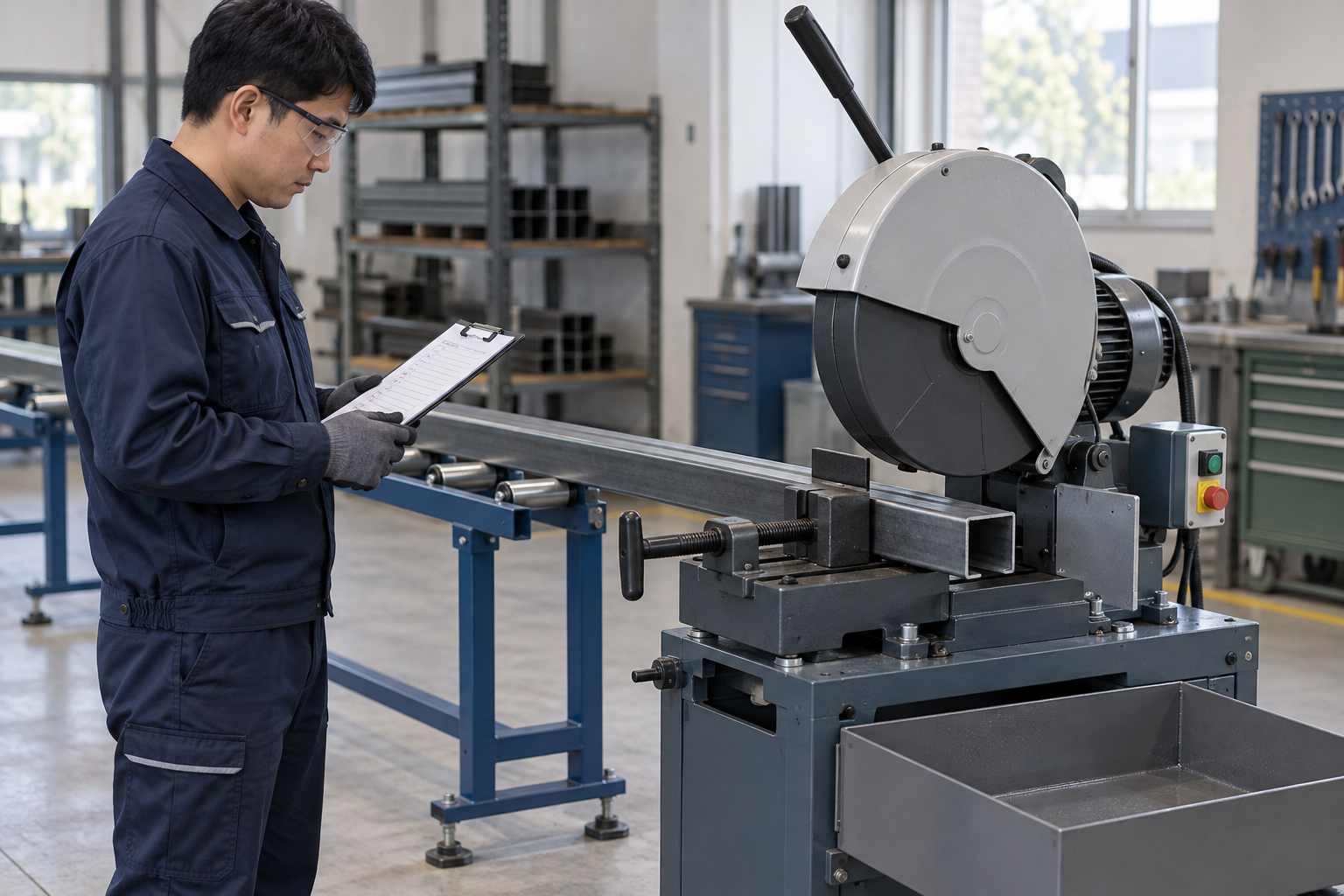
This illustration provides educational context. It is not an actual incident photograph or evidence of equipment suitability; any AI-generated depiction is illustrative only.
The scenario and record comparisons are fictional teaching examples, not records of real incidents, measurements, inspections, signatures or approvals.
| Stage | Fictional situation |
|---|---|
| Initial situation | A fictional worker cuts a long steel section. |
| Changed condition | The projecting end drops slightly and vibration grows despite a tight vise. |
| Failure path | A roller stand sitting on chips has tilted; the worker only reduces feed. |
| Possible outcome | Binding, blade damage and a swinging offcut could injure nearby people. |
| Prevention barrier | Stop, isolate and inspect both restraint and support; correct the base and height, then separately inspect the affected cut. |
Failure mechanisms
Vise restraint and long-stock support perform different jobs. A tight vise does not eliminate the bending moment from an unsupported end; a roller stand cannot resist the cutting forces in place of the vise. Check both load paths and the independent offcut path.
Binding can reflect kerf closure, movement or an unlevel support. Reducing feed without investigating can conceal a deteriorating setup. Stop and isolate before inspecting the blade, vise, stock and supports; never twist trapped stock against a powered blade.
A stop command does not prove the blade has stopped. Keep hands clear through coastdown. Use suitable gloves for isolated sharp-stock handling, while keeping gloves, clothing and hands away from exposed moving parts.
Work sequence: Plan cut → Inspect area → Set up isolated → Clamp and support → Cut and monitor → Stop and inspect → Hold abnormality → Clean and hand over. This is a teaching flow, not a device drawing or a complete operating procedure.
5. Conditional decisions and common errors
| Situation | Required action | Evidence | Proceed when |
|---|---|---|---|
| End sags | Stop and check support | Stand base, height and load path | Support accepted |
| Blade binds | Isolate before release | Blade, kerf and vise condition | Cause corrected |
| Cut finished | Wait before handling | Full stop and offcut support | Safe unloading |
| Setup changed | Recheck before cutting | Blade, stock and support match | Setup released |
Similar observations, different decisions
The scenario and record comparisons are fictional teaching examples, not records of real incidents, measurements, inspections, signatures or approvals.
| Observation | Insufficient conclusion | Required distinction |
|---|---|---|
| Vise handle tight | Clamping force only | Long-end support is still required |
| Less vibration | Symptom reduced | Cause may remain |
| Stop selected | Drive commanded off | Coastdown and isolation remain |
6. Roles and responsibilities
| Role | Responsibility |
|---|---|
| Work supervisor | Confirm stock and drawing and the task scope, resources, interfaces and stop authority. |
| Qualified technical reviewer | Review guard and stop, model limits, compatibility and unresolved technical conditions within assigned competence. |
| Work crew | Apply the listed controls, report changes and stop when evidence or safeguards are missing. |
| Inspector / assessor | Record actual feed and coolant and other relevant checks; do not mark unverified conditions as accepted. |
| Handover authority | Reconcile final safe state, restrictions and outstanding actions before the next task. Role labels do not establish a legal credential. |
Supervision and handover focus
| Stage | Management action | Evidence |
|---|---|---|
| Plan cut | 1. Record stock and drawing2. Record blade and speed basis3. Record weight and support | 1. Stock and drawing2. Blade and speed basis3. Weight and support |
| Inspect area | 1. Record guard and stop2. Record shield and eye ppe3. Record end exclusion | 1. Guard and stop2. Shield and eye PPE3. End exclusion |
| Clamp and support | 1. Record jaw contact2. Record support base and height3. Record offcut path | 1. Jaw contact2. Support base and height3. Offcut path |
| Cut and monitor | 1. Record feed and coolant2. Record stock movement3. Record noise and vibration | 1. Feed and coolant2. Stock movement3. Noise and vibration |
| Hold abnormality | 1. Record fault and cut id2. Record blade and vise3. Record support correction | 1. Fault and cut ID2. Blade and vise3. Support correction |
| Clean and hand over | 1. Record final safe state2. Record waste and floor3. Record held parts | 1. Final safe state2. Waste and floor3. Held parts |
7. Hold points and record comparison
| Hold point | Evidence before release | Actual approval |
|---|---|---|
| HP-0 Scope | Stationary cold circular saw cutting one approved steel section secured in its vise, with independent long-stock and offcut support. | |
| HP-1 Inspect area | Guard and stop; Shield and eye PPE; End exclusion; Floor condition | |
| HP-2 Clamp and support | Jaw contact; Support base and height; Offcut path; Clearance and stance | |
| HP-3 Hold abnormality | Fault and cut ID; Blade and vise; Support correction; Restart authorization | |
| HP-4 Clean and hand over | Final safe state; Waste and floor; Held parts; Recipient and limits |
Hold points are internal project checks. They are not universal statutory permits and do not grant work permission. Reassess after defects, changed conditions and shift changes.
Record comparison
The scenario and record comparisons are fictional teaching examples, not records of real incidents, measurements, inspections, signatures or approvals.
The boxes are static record prompts, not interactive or saved approvals. A tick does not establish suitability or permission to restart. Record the evidence, person, time and unresolved issues; retain the change history.
| Record | Insufficient record | Record checklist |
|---|---|---|
| Plan cut | Only marked “OK” | □ Stock and drawing□ Blade and speed basis□ Weight and support□ Cut identification |
| Clamp and support | Only marked “OK” | □ Jaw contact□ Support base and height□ Offcut path□ Clearance and stance |
| Hold abnormality | Only marked “OK” | □ Fault and cut ID□ Blade and vise□ Support correction□ Restart authorization |
| Clean and hand over | Only marked “OK” | □ Final safe state□ Waste and floor□ Held parts□ Recipient and limits |
8. Site checklist and emergency response
| Site check | Actual result | Person / action |
|---|---|---|
| Plan cut: Stock and drawing; Blade and speed basis; Weight and support; Cut identification | ||
| Inspect area: Guard and stop; Shield and eye PPE; End exclusion; Floor condition | ||
| Set up isolated: Isolation evidence; Blade installation; Speed and rotation; Guard restoration | ||
| Clamp and support: Jaw contact; Support base and height; Offcut path; Clearance and stance | ||
| Cut and monitor: Feed and coolant; Stock movement; Noise and vibration; Guard condition | ||
| Stop and inspect: Full stop; Chip and edge control; Unloading support; Cut inspection | ||
| Hold abnormality: Fault and cut ID; Blade and vise; Support correction; Restart authorization | ||
| Clean and hand over: Final safe state; Waste and floor; Held parts; Recipient and limits |
Stop work
Stop for uncertain blade/material compatibility, unstable support, stock movement, binding, unusual noise or vibration, damaged guards or coolant leakage. Do not force the blade or loosen live stock.
Emergency response
Use the accessible emergency stop when safe, keep clear of moving stock and summon the site emergency response. Isolate before trained recovery; do not pull a trapped person or part through a moving blade. Call 911 for a serious injury.
9. Sources and review limits
Public-source access/review: 2026-10-12.
| Official source | Reviewed scope and limits |
|---|---|
| OSHA 1910.212 | General-industry machine guarding, chips and fixed-machine anchoring. |
| OSHA 1910.147 | Covered servicing and verified hazardous-energy control; construction excluded. |
No actual equipment model, SDS, site measurements, design calculations or authorization record was supplied. Product-specific limits and methods must be verified before use. Federal OSHA is a baseline within its scope; determine the applicable State Plan and local requirements. Manufacturer guidance is not government approval; an incorporated standard differs from voluntary guidance. No nationwide-compliance or expert-approval claim is made.
10. PDF guidance and FAQ
PDF A covers basic task controls; B focuses on technical failures; C covers supervision, records and handover. P/S/R/A, measurements, confirmations and signatures remain blank for actual site assessment.
PDFs are complementary six-stage extracts. Apply all eight body stages and the actual equipment/site procedure.
Can a helper hold the far end?
Use a planned stable support; keeping a helper in the moving-stock path is not a substitute.
Can chips be brushed away while cutting?
No. Stop and establish the safe isolated condition before entering the blade area.
What evidence belongs with the cut?
Identify stock, drawing, blade, clamp/support arrangement, dimensional results and any held parts.
Has a professional verified or approved this document?
No. Public sources and editorial, layout and consistency checks were reviewed using AI. No site inspection or professional technical approval has been performed. Obtain appropriate professional review before use.
11. Revision history and authorship
This is reference content written and revised with AI. It has not been verified or approved by a professional. Review by a suitably qualified professional and site authorization are required before use.
| Date | Version | Change | Review status |
|---|---|---|---|
| 2026-10-12 | US 1.0 | New US edition from assigned Korean source; task decisions, records and PDFs localized. | AI editorial review; no professional technical approval |
Korean edition revision dates: 2026-03-02, 2026-08-01, 2026-09-23. US v1.0 adapts the earlier edition to United States requirements and terminology.
Site reviewers must add their actual qualifications, scope, date and approval only after the review occurs.