Inspect where sparks and heat can travel, including the opposite face, openings, cable insulation and concealed spaces. A clear visible welding face does not clear an inaccessible hidden space.
This reference material was written and revised with AI. It has not been verified or approved by a professional. Review by a suitably qualified professional and required site approval are necessary before field use.
Stop before proceeding
Hold welding if concealed combustibles, existing cable protection, fire watch or ventilation cannot be verified. Stop installation for distorted supports, insecure joints, unsafe access or entry beneath suspended material.
1. Legal and technical scope
Construction installation: 1926.352 governs hot-work fire prevention; 1926.416/.417 address electrical exposure and circuit controls. Tray support and bonding must follow the actual design, product listing and locally adopted electrical code. NFPA 70/NEC and manufacturer guidance are not a blanket OSHA approval.
Confirm whether federal OSHA or an OSHA-approved State Plan covers this employer and worksite; state requirements and public-sector coverage can differ. Apply the task-specific provisions and limitations identified above.
| Basis | Application |
|---|---|
| OSHA 29 CFR 1926.352 | Combustibles, opposite-side fire hazards and fire-watch conditions. |
| OSHA 29 CFR 1926.416 | Construction electrical-contact protection. |
| OSHA 29 CFR 1926.417 | Circuit controls and tagging. |
| Eaton cable tray catalog | Prior Korean source reviewed expansion-joint guidance. Current direct PDF open failed; no claim of new full-text review, no catalog dimensions or blanket bonding exception adopted. Verify the installed system manual. |
| OSHA State Plans | Official overview of federal and State Plan jurisdiction and differing public-sector coverage, checked 2026-10-12. Individual state rules require a site-specific check. |
2. Scope and required inputs
Included scope
Install new cable tray and approved supports; control hot work, lifting, mechanical joints, bonding, expansion provisions and the release to cable pulling.
Separate assessment
Unapproved structural welding, live-cable relocation, using tray as a work platform, cable pulling and energization are excluded. Firestop restoration follows its own approved detail.
| Input | Evidence needed |
|---|---|
| Plan supports | Load and spacing; Weld and anchor detail; Route clearances; Platform plan. |
| Inspect materials | Edge condition; Material and fittings; Lead and return path; Storage restraint. |
| Lift tray | Rigging and signals; Hand clearance; Support connection; Access position. |
| Release for pulling | Allowed cable loading; Support acceptance; Bonding and firestop; Next-crew release. |
No site measurements, equipment manuals for the actual installation, inspection records or signed technical approvals were supplied. Confirm the applicable requirements and actual product instructions before use; record each criterion with its units, source and equipment or work-area ID.
3. Eight-stage JSA
| Job stage | Hazards and effects | Failure factors | Technical and procedural controls | Site verification | P | S | R | A |
|---|---|---|---|---|---|---|---|---|
| 1. Plan supports | 1. Tray collapse2. Anchor failure3. Electrical interference4. Unsafe access | 1. Future load omitted2. Unknown base material3. Route not surveyed4. No work platform | 1. Check cable load2. Verify support design3. Survey services4. Plan separate access | 1. Load and spacing2. Weld and anchor detail3. Route clearances4. Platform plan | ||||
| 2. Control work area | 1. Cable fire2. Electric shock3. Worker fall4. Falling materials | 1. Live circuit exposed2. Isolation unclear3. Unsafe access4. People below work | 1. Control electrical risks2. Verify circuit isolation3. Provide guarded access4. Exclude lower work zone | 1. Existing cable boundary2. Isolation verification3. Access and rails4. Drop-zone control | ||||
| 3. Inspect materials | 1. Sharp-edge cuts2. Loose components3. Welding shock4. Rolling stock | 1. Burrs left exposed2. Mixed tray parts3. Damaged leads4. Unstable storage | 1. Protect cut ends2. Match system parts3. Inspect welding equipment4. Secure stored sections | 1. Edge condition2. Material and fittings3. Lead and return path4. Storage restraint | ||||
| 4. Attach supports | 1. Concealed fire2. Fume exposure3. Falling bracket4. Structural damage | 1. Hidden combustibles2. No fume control3. No temporary support4. Unapproved welding | 1. Inspect both weld sides2. Control fumes at source3. Secure bracket first4. Use approved detail | 1. Openings and fire watch2. Ventilation and PPE3. Temporary support4. Weld and anchor checks | ||||
| 5. Lift tray | 1. Long-load rotation2. Hand crushing3. Unfixed tray falls4. Worker fall | 1. Poor lift balance2. Hand alignment3. Early release4. Standing on tray | 1. Control load balance2. Use alignment tools3. Fasten before release4. Use separate platform | 1. Rigging and signals2. Hand clearance3. Support connection4. Access position | ||||
| 6. Join and bond | 1. Lost continuity2. Excess deflection3. Cable damage4. Expansion restraint | 1. Bonding omitted2. Wrong support spacing3. Sharp ends4. Joint welded solid | 1. Verify bonding detail2. Check support spacing3. Protect cable edges4. Maintain expansion travel | 1. Continuity evidence2. Support and load3. Ends and penetrations4. Guides and joint gap | ||||
| 7. Repair and close | 1. Delayed fire2. Tray shifts3. Cable damage4. Unexpected power | 1. Fire watch ends early2. Joint removed loaded3. Tools on cables4. Isolation handoff lost | 1. Monitor hidden areas2. Support before repair3. Protect existing cables4. Transfer isolation state | 1. Post-work fire checks2. Support sequence3. Cable condition4. Energy-control record | ||||
| 8. Release for pulling | 1. Unresolved collapse2. Cable overload3. Incomplete bonding4. Unsafe later access | 1. Load limits omitted2. Defects unmarked3. Inspection absent4. Platform removed early | 1. Transfer load limits2. Mark unfinished sections3. Link bonding results4. Keep needed access | 1. Allowed cable loading2. Support acceptance3. Bonding and firestop4. Next-crew release |
P = likelihood; S = severity; R = risk under the site method; A = the site-defined acceptance/authorization decision. Complete only after actual assessment. Blank cells and checklist prompts are not completed inspections.
4. Fictional scenario and failure mechanisms
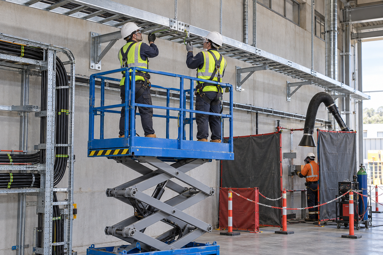
Retained AI-generated educational illustration from the source edition; not a real incident photograph, approved installation drawing or evidence of equipment suitability.
The scenario and record comparisons are fictional teaching examples, not records of real incidents, measurements, inspections, signatures or approvals.
| Item | Fictional scenario |
|---|---|
| Initial | A support bracket is to be welded near existing cables. |
| Change | The cable space beyond a penetration cannot be seen. |
| Failure | The crew treats a shield at the visible weld as complete fire protection. |
| Outcome | Concealed insulation can smolder after the crew leaves. |
| Barrier | Hold welding; examine the full heat path, arrange protection and monitoring, or seek an approved alternative connection method. |
Why the controls matter
Inspect where sparks and heat can travel, including the opposite face, openings, cable insulation and concealed spaces. A clear visible welding face does not clear an inaccessible hidden space.
A rigid-looking tray does not prove support or anchor capacity. Before loading, connect support spacing, base material, weld and anchor inspection to the approved cable load and installation sequence.
Mechanical fastening, electrical continuity and thermal movement are separate functions. Do not weld an expansion joint solid or assume every bolted joint provides the required bonding.
Decision sequence
| Step | Decision |
|---|---|
| Known | The cable space beyond a penetration cannot be seen. |
| Unknown | Actual condition, extent of damage and suitability of rigging and signals, hand clearance remain to be established. |
| Hold | The crew treats a shield at the visible weld as complete fire protection. |
| Evidence | Link rigging and signals, hand clearance, support connection, access position, post-work fire checks, support sequence to the affected equipment or work area. |
| Next | Hold welding; examine the full heat path, arrange protection and monitoring, or seek an approved alternative connection method. |
5. Conditional decisions and common errors
| Condition | Action | Evidence | Proceed when |
|---|---|---|---|
| Hidden space | Hold welding and inspect heat paths | Opposite-side and opening survey | Fire paths controlled |
| Unfixed tray | Keep rigging and exclude people | Support and fastening check | Tray secured |
| Expansion joint | Verify movement and bonding detail | System drawing and inspection | Movement retained |
| Cable pulling | Transfer load and defect limits | Support, bonding and fire closure | Section released |
Similar appearance, different evidence
The scenario and record comparisons are fictional teaching examples, not records of real incidents, measurements, inspections, signatures or approvals.
| Comparison | Supported decision | Insufficient basis |
|---|---|---|
| Condition | Opposite-side and opening survey | Hidden space has not been resolved. |
| Evidence | System drawing and inspection | A photograph or a completed-looking task without the relevant inspection record. |
| Release | Section released | Completion of one step does not release the excluded tasks in section 2. |
6. Roles and responsibilities
| Role | Responsibility |
|---|---|
| Work supervisor | Assign the task boundary, stop authority, interfaces and emergency communication for cable tray installation and support welding. |
| Technical lead | Confirm Load and spacing; Weld and anchor detail; Route clearances; Platform plan. Resolve design and manufacturer limits before work. |
| Authorized crew | Apply Edge condition; Material and fittings; Lead and return path; Storage restraint. Stop when the working arrangement changes. |
| Inspector / receiving lead | Review Rigging and signals; Hand clearance; Support connection; Access position. Transfer Allowed cable loading; Support acceptance; Bonding and firestop; Next-crew release. |
Role labels allocate responsibilities; they do not confer a legal qualification. Verify the competence, training and authority required for the actual task.
Record and handoff perspective
| Stage | Record controls | Verification |
|---|---|---|
| Plan supports | 1. Record load and spacing2. Record weld and anchor detail3. Record route clearances | 1. Weld and anchor detail2. Route clearances3. Platform plan |
| Inspect materials | 1. Record edge condition2. Record material and fittings3. Record lead and return path | 1. Material and fittings2. Lead and return path3. Storage restraint |
| Attach supports | 1. Record openings and fire watch2. Record ventilation and ppe3. Record temporary support | 1. Ventilation and PPE2. Temporary support3. Weld and anchor checks |
| Lift tray | 1. Record rigging and signals2. Record hand clearance3. Record support connection | 1. Hand clearance2. Support connection3. Access position |
| Repair and close | 1. Record post-work fire checks2. Record support sequence3. Record cable condition | 1. Support sequence2. Cable condition3. Energy-control record |
| Release for pulling | 1. Record allowed cable loading2. Record support acceptance3. Record bonding and firestop | 1. Support acceptance2. Bonding and firestop3. Next-crew release |
7. Hold points and record comparison
| Hold point | Evidence before release | Actual record |
|---|---|---|
| HP-0 Start | Install new cable tray and approved supports; control hot work, lifting, mechanical joints, bonding, expansion provisions and the release to cable pulling. | |
| HP-1 Control work area | Existing cable boundary; Isolation verification; Access and rails; Drop-zone control | |
| HP-2 Attach supports | Openings and fire watch; Ventilation and PPE; Temporary support; Weld and anchor checks | |
| HP-3 Join and bond | Continuity evidence; Support and load; Ends and penetrations; Guides and joint gap | |
| HP-4 Release for pulling | Allowed cable loading; Support acceptance; Bonding and firestop; Next-crew release |
These are internal hold points, not issued permits. Recheck affected points after a change, fault or shift handoff; link the actual approval record.
Record comparison
The scenario and record comparisons are fictional teaching examples, not records of real incidents, measurements, inspections, signatures or approvals.
The boxes are static record prompts, not interactive or saved approvals. A tick does not establish suitability or permission to restart. Record the evidence, person, time and unresolved issues; retain the change history.
| Record | Insufficient | Record checklist |
|---|---|---|
| Plan supports | "Checked" without target, criteria or result | □ Load and spacing□ Weld and anchor detail□ Route clearances□ Platform plan |
| Inspect materials | "Checked" without target, criteria or result | □ Edge condition□ Material and fittings□ Lead and return path□ Storage restraint |
| Lift tray | "Checked" without target, criteria or result | □ Rigging and signals□ Hand clearance□ Support connection□ Access position |
| Release for pulling | "Checked" without target, criteria or result | □ Allowed cable loading□ Support acceptance□ Bonding and firestop□ Next-crew release |
8. Site checklist and emergency response
| Check | Result | Person / action |
|---|---|---|
| □ Plan supports: Load and spacing | ||
| □ Control work area: Existing cable boundary | ||
| □ Inspect materials: Edge condition | ||
| □ Attach supports: Openings and fire watch | ||
| □ Lift tray: Rigging and signals | ||
| □ Join and bond: Continuity evidence | ||
| □ Repair and close: Post-work fire checks | ||
| □ Release for pulling: Allowed cable loading | ||
| □ Emergency access and handoff restrictions |
Stop work
Hold welding if concealed combustibles, existing cable protection, fire watch or ventilation cannot be verified. Stop installation for distorted supports, insecure joints, unsafe access or entry beneath suspended material.
Emergency response
Stop from a safe location, exclude people from the affected danger zone and activate the site emergency plan. Call 911 for injury or immediate danger. Do not enter an unstable, energized or confined danger area for an improvised rescue; trained responders must control the specific energy and access hazards.
9. Sources and review limits
Public-source review: 2026-10-12. Official regulation pages and specific technical references are distinguished below; no agency or manufacturer has approved this content.
| Source | Reviewed scope and limitation |
|---|---|
| OSHA 29 CFR 1926.352 | Combustibles, opposite-side fire hazards and fire-watch conditions. |
| OSHA 29 CFR 1926.416 | Construction electrical-contact protection. |
| OSHA 29 CFR 1926.417 | Circuit controls and tagging. |
| Eaton cable tray catalog | Prior Korean source reviewed expansion-joint guidance. Current direct PDF open failed; no claim of new full-text review, no catalog dimensions or blanket bonding exception adopted. Verify the installed system manual. |
| OSHA State Plans | Official overview of federal and State Plan jurisdiction and differing public-sector coverage, checked 2026-10-12. Individual state rules require a site-specific check. |
No site measurements, equipment manuals for the actual installation, inspection records or signed technical approvals were supplied. Confirm the applicable requirements and actual product instructions before use; record each criterion with its units, source and equipment or work-area ID.
10. PDF guidance and FAQ
PDF A covers basic task controls; B focuses on technical failures; C covers supervision, records and handover. The article has eight stages with four items per main cell; each PDF has six key stages with three items per main cell. P/S/R/A, measurements, confirmations and signatures remain blank for actual site assessment.
Content group
jsa-cabletray-installation
May cable tray serve as a work platform?
No. Provide separate safe access and fall protection.
Is a clean welding face sufficient?
No. Check the opposite side, openings and concealed heat or spark paths.
Can a moving expansion joint be welded solid?
Not without an approved redesign; movement may be intentional.
Do tightened bolts prove electrical continuity?
No. Verify the actual approved bonding arrangement and required checks separately.
Has a professional approved this JSA?
This reference material was written and revised with AI. It has not been verified or approved by a professional. Review by a suitably qualified professional and required site approval are necessary before field use.
11. Revision history and authorship
This reference material was written and revised with AI. It has not been verified or approved by a professional. Review by a suitably qualified professional and required site approval are necessary before field use.
Korean source created 2026-09-20. This US edition adapts the Korean source; earlier editorial revisions do not constitute professional approval of this edition.
| Date | Edition | Change | Review status |
|---|---|---|---|
| 2026-10-12 | 1.0 | US localization: preserve task judgments; replace Korean legal applicability with scoped US references. | AI editorial and output checks; no professional technical approval. |