Planned earth pushing and surface grading with an identified crawler bulldozer on an accepted work area with defined travel, edge and pedestrian boundaries.
Stop for new cracks, track settlement, exposed services, abnormal resistance, defective braking or steering, lost rear visibility or signals, or entry of people into the machine envelope.
Reference content written and revised with AI. It has not been verified or approved by a professional. Review by a suitably qualified professional and site approval are required before use.
1. Legal and technical scope
For construction crawler-dozer work, review OSHA 1926.602(a) equipment, access, braking, seat-belt and warning provisions, 1926.600 for equipment support and unattended controls, and Subpart W including 1926.1000 for the applicable ROPS scope and manufacture-date requirements. Use the actual equipment classification and limitations; this JSA does not establish engineering ground capacity or a universal operating slope.
Determine Federal OSHA or the applicable OSHA-approved State Plan, including public/private employer coverage. State Plans must be at least as effective and can impose different or additional requirements. The actual activity determines construction versus general-industry scope. Manufacturer instructions, consensus standards, project design and site approvals have distinct roles; this page is not a finding of nationwide compliance.
| Basis | Application and limits |
|---|---|
| OSHA 1926.602 | Applicable earthmoving equipment, safe access grades, brakes, restraints and reversing-warning provisions. |
| OSHA 1926.600 | Applicable equipment support, attachment and parking precautions. |
| OSHA 1926.1000 | ROPS equipment coverage and manufacture-date distinctions; actual machine documentation remains necessary. |
2. Scope and required inputs
Included: Planned earth pushing and surface grading with an identified crawler bulldozer on an accepted work area with defined travel, edge and pedestrian boundaries.
Separate review: Steep-slope pioneering, demolition, disabled-machine towing or recovery and removal of embedded utilities require separate plans.
| Input | Required evidence |
|---|---|
| Review ground and plan | Ground support evidence; Fill void and service locations; Drainage and recent weather; Machine and grading plan |
| Inspect machine | Tracks and control checks; Blade hoses and fasteners; ROPS belt and access condition; Horn and reversing protection |
| Push and grade | Push location depth and load; Ground and slope response; Marked services and obstructions; Exclusion and visibility |
| Park and hand over | Machine parking state; Cracks steps and services; Remaining exclusions; Receiving crew and limits |
Review fill history, voids, drainage, ground support and utilities against the actual machine and blade work. Set site-specific edge limits, push depth and direction, load and slope restrictions, trial work and change triggers. Track ground pressure alone is not proof of edge stability. Recovery loads and towing connections are outside routine grading.
3. Eight-stage JSA
P = likelihood; S = severity; R = risk under the site method; A = acceptance or authorization as defined by the site. Leave these blank until actual assessment and control verification. A low score does not override a legal requirement, product limit or unreleased hold point.
| Job stage | Hazards and effects | Failure factors | Required controls | Site verification | P | S | R | A |
|---|---|---|---|---|---|---|---|---|
| 1. Review ground and plan | 1. Ground settlement2. Buried-service damage3. Backfill-edge collapse4. Void collapse | 1. Ground history missing2. Drawings differ from site3. Yesterday conditions reused4. Drainage change ignored | 1. Review fill voids and services2. Confirm actual equipment route3. Reassess after rain or change4. Set planned push sequence | 1. Ground support evidence2. Fill void and service locations3. Drainage and recent weather4. Machine and grading plan | ||||
| 2. Control edges and people | 1. Reversing collision2. Fall beyond edge3. Soil strikes workers below4. Spotter crushed | 1. Walking route overlaps2. Edge limits undefined3. Work continues below4. Spotter position unsafe | 1. Separate pedestrian routes2. Mark reviewed approach limits3. Exclude lower affected area4. Agree safe spotter positions | 1. Edge and approach boundary2. Rear path and sight lines3. Lower-area exclusion4. Signals and waiting positions | ||||
| 3. Inspect machine | 1. Brake or steering failure2. Hydraulic fire3. Track derailment4. Uncontrolled blade descent | 1. Controls defective2. Hose damage ignored3. Track wear unreviewed4. Protection damaged | 1. Check tracks brakes and steering2. Inspect blade and hydraulic parts3. Verify warning devices4. Use intended ROPS and restraint | 1. Tracks and control checks2. Blade hoses and fasteners3. ROPS belt and access condition4. Horn and reversing protection | ||||
| 4. Enter and trial | 1. Local support loss2. Unexpected tilt3. Drainage-ditch fall4. Unstable travel | 1. Route capacity unaccepted2. Machine width overlooked3. Ditch edge hidden4. Old route assumed safe | 1. Use accepted entry route2. Observe trial ground response3. Check drains and boundaries4. Stop for cracking or settlement | 1. Route and machine fit2. Trial track impressions3. Drainage and edge location4. Tilt and support changes | ||||
| 5. Push and grade | 1. Edge collapse2. Blade reaction overturn3. Thrown material strike4. Exposed-service damage | 1. Excessive push load2. Cut depth exceeds plan3. Exclusion breached4. Service marks displaced | 1. Follow accepted depth and direction2. Monitor soil and machine response3. Keep people outside work envelope4. Hold newly exposed services | 1. Push location depth and load2. Ground and slope response3. Marked services and obstructions4. Exclusion and visibility | ||||
| 6. Reverse turn and traverse | 1. Rollover2. Person struck behind3. Track slip4. Blind-spot collision | 1. Abrupt maneuver2. Cross-slope change ignored3. Rear route not checked4. Signal lost | 1. Follow actual travel limitations2. Check path before movement3. Use agreed reversing controls4. Stop when sight or signal is lost | 1. Grade and direction2. Rear route and people3. Warning and signal status4. Steps and track support | ||||
| 7. Stop and address faults | 1. Blade-drop crush2. Recovery-line recoil3. Further settlement4. Towing-point failure | 1. Hydraulics alone hold blade2. Recovery improvised3. Recovery load unknown4. Temporary connector used | 1. Lower or secure attachments2. Isolate and mechanically support3. Separate recovery from grading4. Exclude recoil and unstable areas | 1. Blade and movement control2. Isolation and support evidence3. Separate recovery plan4. Repair and restart authority | ||||
| 8. Park and hand over | 1. Unattended movement2. Unsafe next-trade access3. Parking-ground settlement4. Exposed-service strike | 1. Blade left raised2. Cracks not transferred3. Soft parking location4. Restrictions left verbal | 1. Park on accepted support2. Lower attachments as specified3. Identify open ground and services4. Transfer access restrictions | 1. Machine parking state2. Cracks steps and services3. Remaining exclusions4. Receiving crew and limits |
4. Hypothetical scenario and failure mechanisms
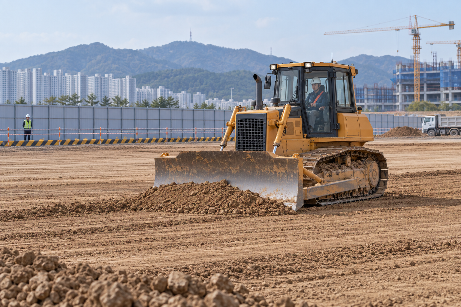 Retained source illustration: an AI-generated educational concept, not a real incident photograph or evidence of equipment suitability.
The following scenario, comparisons and example records are hypothetical teaching material. They do not reproduce actual incidents, measurements, signatures or approvals.
| Item | Hypothetical situation |
|---|---|
| Initial state | A crawler dozer pushes soil beside a backfilled edge. |
| Change | After rain, water ponds and one track leaves a progressively deeper impression. |
| Failure path | The operator relies on the level appearance and the previous day of successful work. |
| Possible harm | Local support loss combined with blade reaction can cause settlement or overturning. |
| Barrier | Stop affected travel, control access and reassess drainage, ground support, edge limits and pushing direction before a reviewed trial. |
Surface shape and bearing support are different facts. Rain, drainage changes and deeper track marks trigger review of the ground assessment, even when the planned final grade has not changed.
Blade reaction, steps and cross-slope travel change stability. The potential ground failure surface may extend beyond the visible edge. Use the actual ground and machine assessment rather than a universal setback or slope angle.
ROPS and the appropriate restraint reduce particular operator hazards but do not prevent ground failure. Preserve the intended protective configuration, inspect it and use the restraint as required by the actual machine and applicable rules.
A disabled-machine recovery is a new loading case. Towing points, rigging, recovery equipment, ground support and recoil exposure need a separate accepted plan. Adding pulling force without that review can worsen settlement or cause a connection failure.
| Decision | Reason and evidence |
|---|---|
| Known facts | After rain, water ponds and one track leaves a progressively deeper impression. |
| Unresolved | The operator relies on the level appearance and the previous day of successful work. |
| Hold reason | Stop for new cracks, track settlement, exposed services, abnormal resistance, defective braking or steering, lost rear visibility or signals, or entry of people into the machine envelope. |
| Evidence needed | Route and machine fit; Trial track impressions; Drainage and edge location; Tilt and support changes. |
| Next decision | Stop affected travel, control access and reassess drainage, ground support, edge limits and pushing direction before a reviewed trial. |
5. Conditional decisions and common errors
| Condition | Action | Evidence | Proceed when |
|---|---|---|---|
| Track settlement | Stop affected entry and pushing. | Ground and drainage assessment. | Support accepted. |
| Service exposed | Exclude affected area. | Service owner and location review. | Protection accepted. |
| Blade maintenance | Control gravity and stored energy. | Isolation and mechanical support. | Access safe. |
| Machine disabled | Hold improvised towing. | Separate recovery plan. | Recovery authorized. |
| Comparison | Situation A | Situation B |
|---|---|---|
| Level work surface | Fill, voids and drainage have been reviewed. | Appearance is the only support evidence. |
| Machine stuck | A separate recovery plan controls load and recoil. | Another machine pulls immediately. |
6. Roles and responsibilities
| Role | Responsibility |
|---|---|
| Work supervisor | Confirm scope, task sequence, exclusion and stop authority. Coordinate review ground and plan with affected operations. |
| Technical reviewer | Resolve the actual design and equipment limits: Ground support evidence; Fill void and service locations; Drainage and recent weather; Machine and grading plan. |
| Work crew | Perform inspect machine using the approved procedure; report any mismatch before proceeding. |
| Inspector / assessor | Verify Grade and direction; Rear route and people; Warning and signal status; Steps and track support. Record what was actually checked and what remains unresolved. |
| Release / receiving authority | Confirm Machine parking state; Cracks steps and services; Remaining exclusions; Receiving crew and limits. Transfer restrictions and the next permitted stage. |
These are responsibility examples, not invented statutory credentials. Meet the actual training, competent-person, qualified-person and licensing requirements for the assigned work. Anyone may raise a hazard and request a stop; only the designated authority may release the affected stage after evidence is reviewed.
7. Hold points and record comparison
| Hold point | Evidence before release | Confirmation / approval |
|---|---|---|
| HP-0 Start | Scope, jurisdiction, equipment identity, responsible people and emergency arrangements. | |
| HP-1 Control edges and people | Edge and approach boundary; Rear path and sight lines; Lower-area exclusion; Signals and waiting positions | |
| HP-2 Enter and trial | Route and machine fit; Trial track impressions; Drainage and edge location; Tilt and support changes | |
| HP-3 Stop and address faults | Blade and movement control; Isolation and support evidence; Separate recovery plan; Repair and restart authority | |
| HP-4 Park and hand over | Machine parking state; Cracks steps and services; Remaining exclusions; Receiving crew and limits |
Hold points are internal evidence gates. They do not replace statutory permits or actual signatures. Recheck affected gates after a change, abnormal event or shift transfer. The blank record must identify the evidence, person, time, limits and release scope.
| Record | Insufficient record | Record checklist |
|---|---|---|
| Ground | Looks level | □ Ground support evidence□ Fill void and service locations□ Drainage and recent weather□ Machine and grading plan |
| Boundary | Enough clearance | □ Edge and approach boundary□ Rear path and sight lines□ Lower-area exclusion□ Signals and waiting positions |
| Trial | Worked yesterday | □ Route and machine fit□ Trial track impressions□ Drainage and edge location□ Tilt and support changes |
| Handover | Finished grading | □ Machine parking state□ Cracks steps and services□ Remaining exclusions□ Receiving crew and limits |
The □ boxes are static prompts, not saved or interactive approvals. Each checks one record element. A tick alone does not establish suitability or permission to restart. Link equipment IDs and supporting records; retain unresolved matters and the earlier record when conditions change.
8. Site checklist and emergency response
| Check item | Result | Person / action |
|---|---|---|
| Ground support evidence | ||
| Edge and approach boundary | ||
| Tracks and control checks | ||
| Route and machine fit | ||
| Push location depth and load | ||
| Grade and direction | ||
| Blade and movement control | ||
| Machine parking state | ||
| Emergency arrangements and unresolved restrictions communicated |
Stop work: Stop for new cracks, track settlement, exposed services, abnormal resistance, defective braking or steering, lost rear visibility or signals, or entry of people into the machine envelope.
Emergency response: Withdraw personnel and other equipment from cracking or settling ground and control access. Call 911 for serious injury and use the planned response. Do not worsen the situation with improvised towing or an approach beneath an unsupported blade.
9. Sources and review limits
Official-source review date: October 14, 2026. The following review is limited to the public provisions or selected manufacturer material identified below. It does not establish that any authority approved this article or the actual installation.
- OSHA 1926.602: Applicable earthmoving equipment, safe access grades, brakes, restraints and reversing-warning provisions.
- OSHA 1926.600: Applicable equipment support, attachment and parking precautions.
- OSHA 1926.1000: ROPS equipment coverage and manufacture-date distinctions; actual machine documentation remains necessary.
- OSHA State Plans: jurisdiction and coverage overview; identify the actual state program before use.
Paid consensus standards and site-specific calculations, manuals, inspection records and product certificates were not independently obtained or verified unless specifically identified. Korean legal citations remain in the preserved Korean source as source history; they are not represented as US legal duties.
10. PDF guidance and FAQ
PDF A covers basic task controls; B examines technical failures; C focuses on supervision, evidence and handover. Each has six rows and three items per main cell. They are complementary extracts: apply all eight body stages and the applicable site procedure. An omitted stage is not permission to omit its controls. PDF HP-0 through HP-4 are worksheet labels; match the event, evidence and authority rather than assuming they match another permit by number.
P/S/R/A, actual measurements, confirmations and signatures remain blank. The PDFs are uncompleted reference worksheets, not issued work permits.
Content group ID: jsa-bulldozer-grading
Does a flat surface prove adequate support?
No. Check fill, voids, drainage, edges and actual equipment loading.
Is one edge setback suitable everywhere?
No. Ground, slope geometry, machine and blade work determine the reviewed limit.
Can another machine immediately pull a stuck dozer?
Recovery requires a separate plan for points, rigging, loads, support and recoil exposure.
Do ROPS and a seat belt prevent slope failure?
No. They do not replace ground stability and operating-limit controls.
Has a professional verified or approved this document?
No. This is AI-assisted reference material. Editorial and layout checks are not a physical inspection or professional technical approval. Obtain qualified professional review and required site approval before use.
11. Revision history and authorship
Reference content written and revised with AI. It has not been verified or approved by a professional. Review by a suitably qualified professional and site approval are required before use.
This system has not physically inspected the equipment, structures, ground, atmosphere or worksite. The document does not replace legal advice, manufacturer procedures, engineering design, inspection certificates, qualification evidence, the site risk assessment or an actual work permit.
Before use, a suitably qualified and authorized person must review the actual equipment, loads, methods, protection, inspection and emergency arrangements and resolve open issues. Record the real reviewer, organization, qualifications, delegated authority, reviewed documents, date, signature, exclusions and conditions of approval separately.
| Date | Version | Change | Review status |
|---|---|---|---|
| 2026-09-19 | 1.0 | Korean source revision retained in the source snapshot. | Historical editorial status; not US professional approval. |
| 2026-10-02 | 1.1 | Korean source revision retained in the source snapshot. | Historical editorial status; not US professional approval. |
| 2026-10-14 | US 1.0 | US localization of the assigned Korean source; task reasoning, educational image and history retained; US scope and sources reviewed. | AI-assisted editorial work; professional approval not performed. |