Planning the actual shipping configuration, unloading and lifting a boiler body, seating its saddles or base, checking alignment and supports, and handing over the mechanically secured installation.
Stop for unknown shipping mass or center of gravity, unverified lifting points, inadequate foundation reactions, tilt, settlement, support gaps, anchor conflicts or lost signals.
Reference content written and revised with AI. It has not been verified or approved by a professional. Review by a suitably qualified professional and site approval are required before use.
1. Legal and technical scope
Construction installation must be assessed under applicable Part 1926 lifting and rigging requirements, including 1926.251 for rigging and the applicable crane provisions for the actual equipment. Maintenance within general industry may instead involve Part 1910 requirements. A rigging rule does not establish boiler support design, pressure-vessel acceptance or permission to fire. Identify the state/local boiler authority and project requirements separately.
Determine Federal OSHA or the applicable OSHA-approved State Plan, including public/private employer coverage. State Plans must be at least as effective and can impose different or additional requirements. The actual activity determines construction versus general-industry scope. Manufacturer instructions, consensus standards, project design and site approvals have distinct roles; this page is not a finding of nationwide compliance.
| Basis | Application and limits |
|---|---|
| OSHA 1926.251 | Construction rigging inspection, identification and capacity requirements; not a foundation or saddle design standard. |
2. Scope and required inputs
Included: Planning the actual shipping configuration, unloading and lifting a boiler body, seating its saddles or base, checking alignment and supports, and handing over the mechanically secured installation.
Separate review: Fuel, water and steam connection completion, pressure testing, firing and performance commissioning are separate releases. Unapproved changes to lifting lugs, saddles, anchors or base details are outside this scope.
| Input | Required evidence |
|---|---|
| Plan body and base | Actual mass and CG; Foundation design reference; Lug and saddle details; Movement allowance drawing |
| Inspect body and rigging | Lug and rigging inspection; Rating and angle check; Accessory security; Connection seating |
| Seat and align | Saddle contact evidence; Level and position record; Foundation bearing check; Gap correction method |
| Hand over | Installation survey; Anchor and grout records; Connection and firing limits; Receiving authority record |
Confirm actual lifted mass, center of gravity, lifting configuration, foundation reactions, saddle contact, anchor installation and grout acceptance. Select handling protection and safe access for the lift. Use the actual design and manufacturer values with units and document revisions.
3. Eight-stage JSA
P = likelihood; S = severity; R = risk under the site method; A = acceptance or authorization as defined by the site. Leave these blank until actual assessment and control verification. A low score does not override a legal requirement, product limit or unreleased hold point.
| Job stage | Hazards and effects | Failure factors | Required controls | Site verification | P | S | R | A |
|---|---|---|---|---|---|---|---|---|
| 1. Plan body and base | 1. Dropped boiler2. Foundation failure3. Overturning4. Future thermal stress | 1. Catalog mass used alone2. Local reactions omitted3. CG not established4. Sliding saddle restrained | 1. Verify shipping configuration2. Check support reactions3. Confirm lift points and CG4. Identify fixed and sliding ends | 1. Actual mass and CG2. Foundation design reference3. Lug and saddle details4. Movement allowance drawing | ||||
| 2. Prepare lift area | 1. Crane instability2. Suspended-load strike3. Collision with services4. Lost operator control | 1. Ground capacity unknown2. Exclusion incomplete3. Route clearance absent4. Signals not agreed | 1. Follow engineered lift plan2. Separate the danger area3. Survey route and overheads4. Assign one signal system | 1. Equipment configuration2. Ground and route evidence3. Service clearance4. Signal and stop briefing | ||||
| 3. Inspect body and rigging | 1. Lug or sling failure2. Shell or nozzle damage3. Dropped loose parts4. Pinch injury | 1. Damaged lifting point2. Rigging on wrong part3. Shipping parts unsecured4. Hands near tensioned gear | 1. Inspect specified lift points2. Use suitable rated rigging3. Secure loose accessories4. Keep hands clear | 1. Lug and rigging inspection2. Rating and angle check3. Accessory security4. Connection seating | ||||
| 4. Trial lift and move | 1. Unexpected rotation2. Unequal sling loading3. Collision and crushing4. Load instability | 1. CG estimate wrong2. Snagged attachment3. Route changed4. Signal lost | 1. Check balance at low height2. Stop on snag or tilt3. Move within lift plan4. Stop if communication fails | 1. Balance and load behavior2. All connections clear3. Route remains controlled4. Continuous communication | ||||
| 5. Seat and align | 1. Support overload2. Boiler shift3. Crushed fingers4. Base distortion | 1. One saddle not contacting2. Wrong bearing location3. Hands used as guides4. Anchors force alignment | 1. Use planned landing supports2. Verify level and contact3. Use hands-clear tools4. Correct fit by design method | 1. Saddle contact evidence2. Level and position record3. Foundation bearing check4. Gap correction method | ||||
| 6. Secure and release | 1. Sudden load transfer2. Anchor failure3. Thermal movement restraint4. Grout support failure | 1. Hook released early2. Wrong anchor setting3. Sliding end fixed4. Grout strength unverified | 1. Install specified restraint2. Check anchor installation3. Preserve movement details4. Release after support acceptance | 1. Anchor inspection record2. Fixed and sliding checks3. Grout acceptance evidence4. Release-to-unhook record | ||||
| 7. Correct a defect | 1. Unstable-load collapse2. Shell distortion3. Uncontrolled relift4. Repeat settlement | 1. Live anchor correction2. Unreviewed shimming3. Defect cause ignored4. Load state misunderstood | 1. Stop and clear affected zone2. Plan safe support or relift3. Resolve cause with designer4. Reinspect corrected stage | 1. Defect and load state2. Recovery method authority3. Correction evidence4. Repeat support inspection | ||||
| 8. Hand over | 1. Premature firing2. Piping nozzle overload3. Unrecorded movement limit4. Unresolved defect use | 1. Placement treated commissioning2. Next-trade load ignored3. Drawings not updated4. Restrictions not transferred | 1. Issue mechanical handover2. Require separate connection review3. Record movement constraints4. Transfer outstanding holds | 1. Installation survey2. Anchor and grout records3. Connection and firing limits4. Receiving authority record |
4. Hypothetical scenario and failure mechanisms
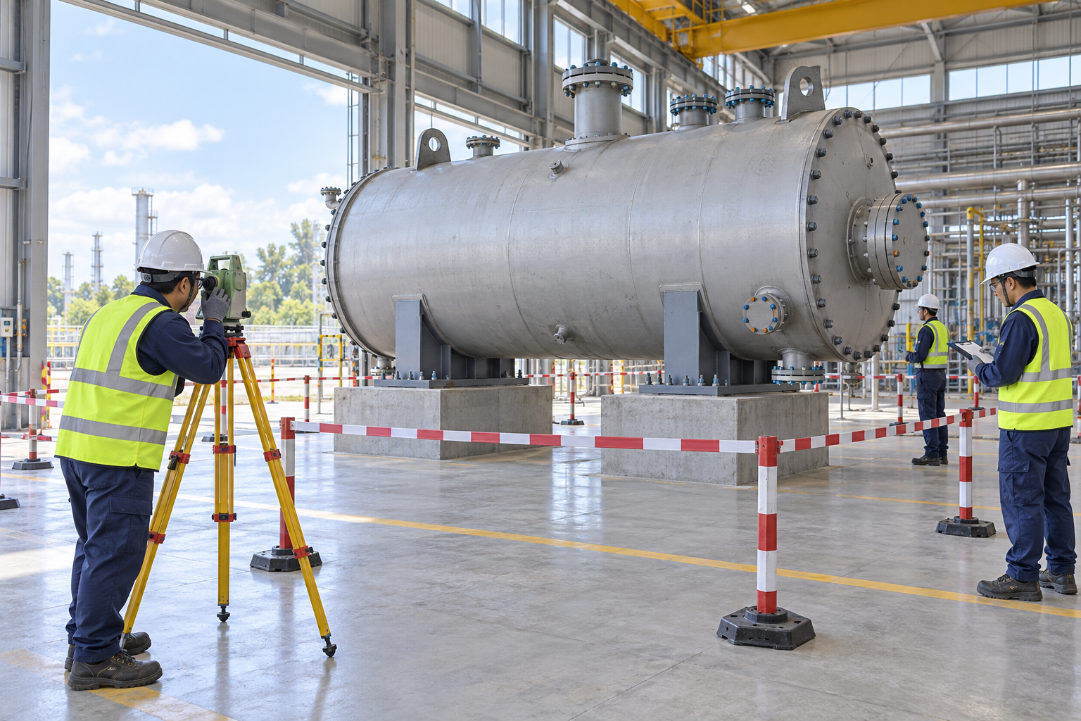 Retained source illustration: an AI-generated educational concept, not a real incident photograph or evidence of equipment suitability.
The following scenario, comparisons and example records are hypothetical teaching material. They do not reproduce actual incidents, measurements, signatures or approvals.
| Item | Hypothetical situation |
|---|---|
| Initial state | A boiler is lowered onto its planned supports. |
| Change | One saddle remains clear of the foundation, and the crew proposes tightening the anchors to pull it down before releasing the crane. |
| Failure path | Anchor force can distort the support or shell and conceal a deficient load path rather than correct it. |
| Possible harm | The installation may shift or overload a local support when lifting tension is removed. |
| Barrier | Hold release, maintain a safely controlled load state under the lift plan, and obtain the specified alignment, shim or grout correction. Verify contact, strength and restraint before unhooking. |
Shipping mass includes the actual accessories, packing and any retained fluids, not just catalog dry mass. The center of gravity and approved lifting points must match that configuration. Foundation review must consider local reactions and the erection sequence.
A saddle can be fixed or designed to allow movement. Blocking an intended sliding support can restrain thermal expansion later. Verify which components locate, support or permit movement before fitting anchors.
A support gap is not automatically an anchor-tightening problem. Pulling a base into contact can introduce unintended stress. Correct level, contact and grout conditions by the design method, including any required curing strength before load transfer.
Mechanical placement, piping connection and first firing are different acceptance states. Later piping loads and thermal movement can change the installed load path. Record installation restrictions and transfer them to the next trade.
| Decision | Reason and evidence |
|---|---|
| Known facts | One saddle remains clear of the foundation, and the crew proposes tightening the anchors to pull it down before releasing the crane. |
| Unresolved | Anchor force can distort the support or shell and conceal a deficient load path rather than correct it. |
| Hold reason | Stop for unknown shipping mass or center of gravity, unverified lifting points, inadequate foundation reactions, tilt, settlement, support gaps, anchor conflicts or lost signals. |
| Evidence needed | Anchor inspection record; Fixed and sliding checks; Grout acceptance evidence; Release-to-unhook record. |
| Next decision | Hold release, maintain a safely controlled load state under the lift plan, and obtain the specified alignment, shim or grout correction. Verify contact, strength and restraint before unhooking. |
5. Conditional decisions and common errors
| Condition | Action | Evidence | Proceed when |
|---|---|---|---|
| Mass unknown | Hold lifting and establish the shipping configuration. | Mass, center of gravity and lifting-point documents. | Lift basis confirmed. |
| Support gap | Hold release and obtain the designed correction. | Contact, level, shim or grout evidence. | Specified support contact. |
| Anchor conflict | Stop forced fitting and resolve the design interface. | Anchor details and approved correction. | Correct restraints installed. |
| Ready for next trade | Transfer mechanical acceptance and remaining holds. | Survey, grout, movement and handover records. | Mechanical release scope clear. |
| Comparison | Situation A | Situation B |
|---|---|---|
| Anchors installed | Contact, level, anchor installation and fixed/sliding details are verified. | Bolts were tightened to conceal a gap. |
| Boiler positioned | Mechanical support is accepted for the stated stage. | The next crew assumes fuel connection and firing are also approved. |
6. Roles and responsibilities
| Role | Responsibility |
|---|---|
| Work supervisor | Confirm scope, task sequence, exclusion and stop authority. Coordinate plan body and base with affected operations. |
| Technical reviewer | Resolve the actual design and equipment limits: Actual mass and CG; Foundation design reference; Lug and saddle details; Movement allowance drawing. |
| Work crew | Perform inspect body and rigging using the approved procedure; report any mismatch before proceeding. |
| Inspector / assessor | Verify Anchor inspection record; Fixed and sliding checks; Grout acceptance evidence; Release-to-unhook record. Record what was actually checked and what remains unresolved. |
| Release / receiving authority | Confirm Installation survey; Anchor and grout records; Connection and firing limits; Receiving authority record. Transfer restrictions and the next permitted stage. |
These are responsibility examples, not invented statutory credentials. Meet the actual training, competent-person, qualified-person and licensing requirements for the assigned work. Anyone may raise a hazard and request a stop; only the designated authority may release the affected stage after evidence is reviewed.
7. Hold points and record comparison
| Hold point | Evidence before release | Confirmation / approval |
|---|---|---|
| HP-0 Start | Scope, jurisdiction, equipment identity, responsible people and emergency arrangements. | |
| HP-1 Prepare lift area | Equipment configuration; Ground and route evidence; Service clearance; Signal and stop briefing | |
| HP-2 Trial lift and move | Balance and load behavior; All connections clear; Route remains controlled; Continuous communication | |
| HP-3 Secure and release | Anchor inspection record; Fixed and sliding checks; Grout acceptance evidence; Release-to-unhook record | |
| HP-4 Hand over | Installation survey; Anchor and grout records; Connection and firing limits; Receiving authority record |
Hold points are internal evidence gates. They do not replace statutory permits or actual signatures. Recheck affected gates after a change, abnormal event or shift transfer. The blank record must identify the evidence, person, time, limits and release scope.
| Record | Insufficient record | Record checklist |
|---|---|---|
| Lift basis | Catalog weight checked | □ Actual mass and CG□ Foundation design reference□ Lug and saddle details□ Movement allowance drawing |
| Support | Boiler is down | □ Saddle contact evidence□ Level and position record□ Foundation bearing check□ Gap correction method |
| Release | Bolts tightened | □ Anchor inspection record□ Fixed and sliding checks□ Grout acceptance evidence□ Release-to-unhook record |
| Handover | Installation complete | □ Installation survey□ Anchor and grout records□ Connection and firing limits□ Receiving authority record |
The □ boxes are static prompts, not saved or interactive approvals. Each checks one record element. A tick alone does not establish suitability or permission to restart. Link equipment IDs and supporting records; retain unresolved matters and the earlier record when conditions change.
8. Site checklist and emergency response
| Check item | Result | Person / action |
|---|---|---|
| Actual mass and CG | ||
| Equipment configuration | ||
| Lug and rigging inspection | ||
| Balance and load behavior | ||
| Saddle contact evidence | ||
| Anchor inspection record | ||
| Defect and load state | ||
| Installation survey | ||
| Emergency arrangements and unresolved restrictions communicated |
Stop work: Stop for unknown shipping mass or center of gravity, unverified lifting points, inadequate foundation reactions, tilt, settlement, support gaps, anchor conflicts or lost signals.
Emergency response: Stop lifting or positioning on tilt, settlement or loss of support; clear the potential fall and movement area. Do not send anyone under an unstable boiler to add a shim or tighten an anchor. Use a separately reviewed stabilization or recovery plan. Activate emergency response and call 911 for injury or imminent uncontrolled collapse.
9. Sources and review limits
Official-source review date: October 12, 2026. The following review is limited to the public provisions or selected manufacturer material identified below. It does not establish that any authority approved this article or the actual installation.
- OSHA 1926.251: Construction rigging inspection, identification and capacity requirements; not a foundation or saddle design standard.
- OSHA State Plans: jurisdiction and coverage overview; identify the actual state program before use.
Paid consensus standards and site-specific calculations, manuals, inspection records and product certificates were not independently obtained or verified unless specifically identified. Korean legal citations remain in the preserved Korean source as source history; they are not represented as US legal duties.
10. PDF guidance and FAQ
PDF A covers basic task controls; B examines technical failures; C focuses on supervision, evidence and handover. Each has six rows and three items per main cell. They are complementary extracts: apply all eight body stages and the applicable site procedure. An omitted stage is not permission to omit its controls. PDF HP-0 through HP-4 are worksheet labels; match the event, evidence and authority rather than assuming they match another permit by number.
P/S/R/A, actual measurements, confirmations and signatures remain blank. The PDFs are uncompleted reference worksheets, not issued work permits.
Content group ID: jsa-boiler-positioning
May anchors pull a saddle down into contact?
Do not use anchor force to conceal a support gap. Obtain the designed leveling, shimming or grout correction and verify the load path.
Is catalog dry weight sufficient for the lift?
No. Confirm the actual shipping configuration, accessories, retained contents and center of gravity.
Can the boiler be fired after the crane is released?
No. Mechanical positioning does not release pressure testing, fuel systems, controls or first firing.
Has a professional verified or approved this document?
No. This is AI-assisted reference material. Editorial and layout checks are not a physical inspection or professional technical approval. Obtain qualified professional review and required site approval before use.
11. Revision history and authorship
Reference content written and revised with AI. It has not been verified or approved by a professional. Review by a suitably qualified professional and site approval are required before use.
This system has not physically inspected the equipment, structures, ground, atmosphere or worksite. The document does not replace legal advice, manufacturer procedures, engineering design, inspection certificates, qualification evidence, the site risk assessment or an actual work permit.
Before use, a suitably qualified and authorized person must review the actual equipment, loads, methods, protection, inspection and emergency arrangements and resolve open issues. Record the real reviewer, organization, qualifications, delegated authority, reviewed documents, date, signature, exclusions and conditions of approval separately.
| Date | Version | Change | Review status |
|---|---|---|---|
| 2026-09-19 | 1.1 | Korean source revision retained in the source snapshot. | Historical editorial status; not US professional approval. |
| 2026-09-26 | 1.2 | Korean source revision retained in the source snapshot. | Historical editorial status; not US professional approval. |
| 2026-10-12 | US 1.0 | US localization of the assigned Korean source; task reasoning, educational image and history retained; US scope and sources reviewed. | AI-assisted editorial work; professional approval not performed. |