Bearing replacement transfers bridge load from the existing bearing to temporary support and then to the new bearing. Monitor displacement, reaction and contact together at each stage; hydraulic pressure alone cannot authorize entry.
This is reference content written and revised with AI. It has not been verified or approved by a professional. Review by a suitably qualified professional and required site authorization are necessary before use.
Stop conditions first
Stop lifting or lowering for unequal movement, reaction outside the engineered limits, settlement, cracking, leakage or unstable support. Exclude personnel and do not improvise an extra stroke at one jack.
1. US legal and technical basis
Construction bridge rehabilitation: OSHA 1926.305 covers jack capacity, support and securing the raised load; applicable construction fall protection and rigging requirements also need project review. These provisions do not supply the bridge-specific engineered jacking design or traffic reopening approval.
| Reference | Use and limit |
|---|---|
| OSHA 29 CFR 1926.305 | Jack rating, travel limits, firm support, prompt securing of raised loads and maintenance; no bridge design limits supplied. |
| OSHA 29 CFR 1926.501 | Construction fall-protection applicability must be assessed for actual access and work surfaces. |
| FHWA Technical Advisory 5140.24 | 1993 temporary-works advisory reviewed for design/construction responsibility. Historical technical guidance; not a current project jacking or bearing manual. |
| OSHA State Plans | Federal baseline and State Plan coverage reviewed. Confirm the applicable state program and employer coverage; this edition does not establish nationwide compliance. |
Determine whether Federal OSHA or an applicable State Plan governs the employer and work. Standards incorporated into a regulation must be read in their legally applicable edition. Other NFPA/ANSI guidance and manufacturer instructions have distinct roles; they are not automatically federal law.
2. Scope and required inputs
Included
Engineered lifting, temporary mechanical support, existing bridge-bearing replacement, anchoring/grouting, staged load return and inspection. New bridge erection has a different load state and requires its own plan.
Separate assessment
Unplanned emergency lifts, bearing-type changes, general strengthening, damaged substructure repairs or changed live-traffic conditions require separate structural review.
| Input | Evidence needed |
|---|---|
| Engineer lift | Engineered lift plan; Local strength review; Traffic-control plan; Reaction and movement limits |
| Prepare support | Access and fall protection; Foundation/support design; Exclusion boundary; Equipment and calibration |
| Lift and secure | Differential movement; Contact and reaction; Support inspection; Traffic exclusion |
| Inspect and release | Support-removal criteria; Shipping-restraint status; Defect and monitoring log; Owner traffic decision |
Selected public official provisions were checked on October 12, 2026. This is not a complete legal audit. No actual equipment manual, site measurements, engineering calculations, product certification or professional technical approval was supplied. Full paid NFPA/ANSI standards and state/local amendments were not reviewed. Check actual equipment, jurisdiction and project requirements before use.
Select task-appropriate eye, hand, foot, skin and hearing protection from the exposure assessment. Where respiratory protection is necessary, use the applicable respiratory-protection program; PPE does not replace isolation, guarding, support or ventilation.
3. Eight-stage JSA
| Job stage | Hazards and effects | Failure factors | Controls | Site verification | P | S | R | A |
|---|---|---|---|---|---|---|---|---|
| 1. Engineer lift | 1. Structural instability2. Local jack-point failure3. Live-load change4. Adjacent bearing overload | 1. Load path omitted2. Local strength unchecked3. Traffic uncontrolled4. Limits not defined | 1. Review staged load path2. Design jack-point support3. Control traffic loads4. Define monitoring limits | 1. Engineered lift plan2. Local strength review3. Traffic-control plan4. Reaction and movement limits | ||||
| 2. Prepare support | 1. Fall from access2. Support buckling3. Falling tools4. Hydraulic hose failure | 1. Platform unsuitable2. Foundation weak3. Area below occupied4. Ratings mismatch | 1. Provide safe access2. Verify mechanical support3. Exclude people below4. Inspect matched equipment | 1. Access and fall protection2. Foundation/support design3. Exclusion boundary4. Equipment and calibration | ||||
| 3. Survey bearing | 1. Damaged pier failure2. Restraint release3. Wrong bearing4. Datum movement | 1. Cracks missed2. Direction confused3. Height mismatch4. Zero unchecked | 1. Survey damage and restraint2. Match fixed/guided direction3. Check height and anchors4. Verify stable datum | 1. Damage survey2. Bearing and orientation3. Anchor dimensions4. Datum and zero record | ||||
| 4. Lift and secure | 1. Unequal-lift cracking2. Jack slip3. Sudden descent4. Traffic impact | 1. Movements not compared2. Eccentric contact3. Mechanical support absent4. Traffic enters zone | 1. Lift by engineered stages2. Monitor force and movement3. Secure mechanical support4. Stop under one command | 1. Differential movement2. Contact and reaction3. Support inspection4. Traffic exclusion | ||||
| 5. Replace bearing | 1. Stored-force release2. Crushing descent3. Dropped bearing4. Anchor damage | 1. Restraint order wrong2. Hydraulics alone trusted3. Hands in gap4. Unapproved drilling | 1. Control residual restraints2. Maintain mechanical support3. Use handling/alignment aids4. Refer changes to engineer | 1. Restraint-release plan2. Support maintained3. Hands clear of gap4. Orientation and anchor check | ||||
| 6. Return load | 1. Grout crushing2. Eccentric bearing stress3. Movement restrained4. Uneven lowering | 1. Strength assumed2. Contact gap3. Temperature ignored4. Lowering sequence changed | 1. Verify required strength2. Inspect contact and anchors3. Check installation position4. Lower with monitoring | 1. Grout-strength evidence2. Contact and fixation3. Temperature/movement basis4. Load-return record | ||||
| 7. Respond to fault | 1. Support settlement2. Hose-loss descent3. Secondary collapse4. Crushing during recovery | 1. Alarm ignored2. Load/pressure confused3. Recovery improvised4. Commands conflict | 1. Evacuate unstable zone2. Use engineered safe hold3. Obtain recovery review4. Recheck before restart | 1. Fault location2. Load and pressure state3. Recovery authorization4. Repeated monitoring | ||||
| 8. Inspect and release | 1. Support removed early2. Bearing cannot move3. Unresolved cracking4. Traffic overload | 1. Transfer not accepted2. Shipping restraint retained3. Record omitted4. Owner release absent | 1. Accept completed transfer2. Check movement and fittings3. Transfer crack/movement log4. Obtain traffic release | 1. Support-removal criteria2. Shipping-restraint status3. Defect and monitoring log4. Owner traffic decision |
Actual risk assessments, measurements, checks, approvals and signatures have not been performed. Keep unverified fields blank and link the actual site records. P/S/R/A mean likelihood, severity, site-method risk and site-defined acceptance/authorization; a score cannot waive a required control.
4. Failure mechanisms and hypothetical case
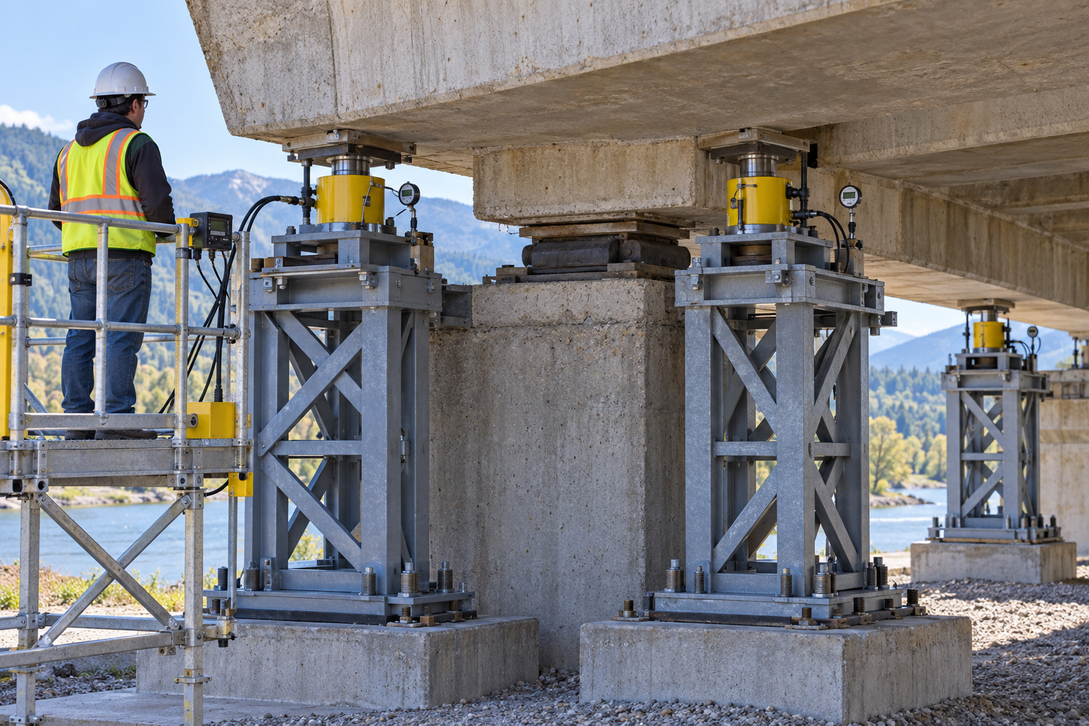
The retained illustration is an AI-generated educational image from the Korean source. It is not an actual incident photograph, approved drawing, equipment certification or proof that the depicted arrangement is safe.
Equal pressure does not necessarily mean equal force: effective piston areas and calibration can differ. Equal force also does not imply equal movement when support stiffness differs. Interpret pressure with the engineered reaction and displacement records.
A closed hydraulic valve is not a substitute for the planned mechanical load-support system. A leak or component failure can change the load rapidly; access below the lifted structure needs verified support and stability.
Bearing orientation, installation position and temperature affect designed movement and rotation. Incorrect restraint can move force into other members. Do not alter anchor holes or bearing direction without engineering review.
Surface-hard grout is not proof of load-bearing strength. Confirm specified material, cure/strength evidence, contact and staged lowering criteria before returning load and removing temporary support.
Hypothetical decision example
Hypothetical example: one jack point rises more than the others, although the pressure gauges look alike. A worker proposes entering before the mechanical support inspection is complete; lifting and access must be held.
The example is fictional; no incident, measurement, inspection or approval is asserted.
Task flow: Engineer lift → Prepare support → Survey bearing → Lift and secure → Replace bearing → Return load → Respond to fault → Inspect and release
5. Hold and proceed decisions
| Condition | Action | Evidence | Proceed when |
|---|---|---|---|
| Unequal movement | Stop and compare reference points/support | Displacement, pressure and reaction record | Cause resolved |
| Entry below bridge | Verify mechanical support load path | Installed support and stability inspection | Support accepted |
| Unknown orientation | Check design position and movement | Bearing drawing, marks and temperature | Position matches design |
| Load return | Verify strength/contact; lower in stages | Grout, anchors and monitoring evidence | Transfer criteria met |
Similar observation, different conclusion
| Observation | Supported conclusion | What remains unresolved |
|---|---|---|
| Similar pressures | Reaction, datum and movement reconciled | Gauge agreement alone leaves loads unknown |
| Load held | Mechanical support inspected | Hydraulics alone cannot release access |
6. Roles and supervision
| Role | Responsibility |
|---|---|
| Work supervisor | Coordinate engineer lift, affected operations, stop signals and stage transitions. |
| Technical/equipment reviewer | Verify Engineered lift plan, Local strength review, actual instructions and unresolved technical limits. |
| Task crew | Apply the stated controls, report changes and keep actual checks and signatures factual. |
| Inspector/test lead | Connect Grout-strength evidence, Contact and fixation to the required acceptance criteria. |
| Receiving authority | Accept the recorded restrictions, Defect and monitoring log, Owner traffic decision, and follow-up ownership. |
These are responsibility examples, not invented statutory credentials. Verify actual competence, training and authority for the assigned work.
Supervision and handover controls
| Stage | Management controls | Evidence |
|---|---|---|
| Plan review | 1. Assign technical owner2. Close task-specific questions3. Review staged load path | 1. Engineered lift plan2. Local strength review3. Reaction and movement limits |
| Competence | 1. Verify required competence2. Assign stop authority3. Provide safe access | 1. Access and fall protection2. Training and task briefing3. Equipment and calibration |
| Prestart evidence | 1. Inspect actual equipment2. Link evidence to this stage3. Lift by engineered stages | 1. Differential movement2. Contact and reaction3. Traffic exclusion |
| Change control | 1. Stop and secure the area2. Review affected controls3. Evacuate unstable zone | 1. Fault location2. Load and pressure state3. Repeated monitoring |
| Shift handover | 1. Identify remaining restrictions2. Confirm receiving responsibility3. Accept completed transfer | 1. Support-removal criteria2. Shipping-restraint status3. Owner traffic decision |
| Closeout | 1. Record defect disposition2. Archive factual evidence3. Accept completed transfer | 1. Support-removal criteria2. Shipping-restraint status3. Owner traffic decision |
7. Hold points and record quality
| Hold point | Evidence before release | Actual record |
|---|---|---|
| HP-0 Start | Engineered lifting, temporary mechanical support, existing bridge-bearing replacement, anchoring/grouting, staged load return and inspection. New bridge erection has a different load state and requires its own plan. | |
| HP-1 Prepare support | Access and fall protection; Foundation/support design; Exclusion boundary; Equipment and calibration | |
| HP-2 Lift and secure | Differential movement; Contact and reaction; Support inspection; Traffic exclusion | |
| HP-3 Respond to fault | Fault location; Load and pressure state; Recovery authorization; Repeated monitoring | |
| HP-4 Inspect and release | Support-removal criteria; Shipping-restraint status; Defect and monitoring log; Owner traffic decision |
Hold points are internal evidence gates. They do not establish that a statutory permit exists or has been approved. Recheck affected gates after changes, faults and shift handover.
Record comparison - hypothetical templates
The 16 boxes below identify record elements, not completed checks or approvals. They are static symbols. Link equipment/location, date, actual findings and the separate record reference; preserve unresolved items.
| Record | Insufficient entry | Required record elements |
|---|---|---|
| Engineer lift | "Checked" without supporting facts | □ Engineered lift plan□ Local strength review□ Traffic-control plan□ Reaction and movement limits |
| Survey bearing | "Checked" without supporting facts | □ Damage survey□ Bearing and orientation□ Anchor dimensions□ Datum and zero record |
| Replace bearing | "Checked" without supporting facts | □ Restraint-release plan□ Support maintained□ Hands clear of gap□ Orientation and anchor check |
| Respond to fault | "Checked" without supporting facts | □ Fault location□ Load and pressure state□ Recovery authorization□ Repeated monitoring |
8. Pre-work checks and emergency response
| Check required | Result | Checker/action |
|---|---|---|
| Engineer lift: Engineered lift plan | ||
| Prepare support: Access and fall protection | ||
| Survey bearing: Damage survey | ||
| Lift and secure: Differential movement | ||
| Replace bearing: Restraint-release plan | ||
| Return load: Grout-strength evidence | ||
| Respond to fault: Fault location | ||
| Inspect and release: Support-removal criteria |
Stop work
Stop lifting or lowering for unequal movement, reaction outside the engineered limits, settlement, cracking, leakage or unstable support. Exclude personnel and do not improvise an extra stroke at one jack.
Emergency response
Stop lifting or lowering under the agreed command and evacuate the unstable support zone. Keep workers out from beneath the bridge; do not adjust a jack or enter to inspect a moving support. Activate the structural emergency and traffic-control plan. Call 911 for injury or collapse and provide the staged load, jack/support locations and traffic status. Recovery requires the responsible engineer and prepared rescue arrangements.
9. Official sources and review limits
Official public-source check: October 12, 2026. The review concerns the selected passages described below, not endorsement of this article.
| Official source | Checked scope and limit |
|---|---|
| OSHA 29 CFR 1926.305 | Jack rating, travel limits, firm support, prompt securing of raised loads and maintenance; no bridge design limits supplied. |
| OSHA 29 CFR 1926.501 | Construction fall-protection applicability must be assessed for actual access and work surfaces. |
| FHWA Technical Advisory 5140.24 | 1993 temporary-works advisory reviewed for design/construction responsibility. Historical technical guidance; not a current project jacking or bearing manual. |
| OSHA State Plans | Federal baseline and State Plan coverage reviewed. Confirm the applicable state program and employer coverage; this edition does not establish nationwide compliance. |
Selected public official provisions were checked on October 12, 2026. This is not a complete legal audit. No actual equipment manual, site measurements, engineering calculations, product certification or professional technical approval was supplied. Full paid NFPA/ANSI standards and state/local amendments were not reviewed. Check actual equipment, jurisdiction and project requirements before use.
This is reference content written and revised with AI. It has not been verified or approved by a professional. Review by a suitably qualified professional and required site authorization are necessary before use.
10. PDF use and frequently asked questions
PDF A summarizes core controls; B emphasizes technical failures; C covers supervision, records and handover. Each uses six stages from or aligned with the eight-stage body. All actual risk, measurement, check and signature fields are blank. Use a separate linked record where more space is needed.
Do matching pressures prove equal lift?
No. Relate effective area, calibration, load path and displacement to the engineered plan.
Can workers enter after closing the valve?
Only after the planned mechanical support, stability and access conditions are verified.
Can fixed and guided directions be swapped?
No. Any change needs structural/design review of movement and force paths.
When may traffic return?
After the owner-defined structural, bearing, load-transfer and traffic-release requirements are satisfied.
Has a professional approved this JSA?
This is reference content written and revised with AI. It has not been verified or approved by a professional. Review by a suitably qualified professional and required site authorization are necessary before use.
11. Authorship and revision history
This is reference content written and revised with AI. It has not been verified or approved by a professional. Review by a suitably qualified professional and required site authorization are necessary before use.
| Date/version | Editorial history | Technical approval |
|---|---|---|
| 2026-09-19 | Korean source retained as an unchanged snapshot; source ID 413432ce-42fe-488b-83a2-52e731def366 | Not asserted |
| 2026-10-12 / US v1.0 | US localization: Retains all eight Korean load-transfer stages, unequal-displacement example, temperature/orientation, grout strength and transport-lock checks. Uses US jack requirements and identifies the older FHWA advisory as technical context rather than a current bearing installation specification. | Not performed |
Source topic: https://smartjsabridge.com/ko/case-study/jsa-bearing-replacement
Content group: jsa-bearing-replacement