A sectional unit and a completed assembly have different weights and centers of gravity. Verify the authorized lifting configuration before rigging, including doors and loose internal components.
This reference material was written and revised with AI. It has not been verified or approved by a professional. Review by a suitably qualified professional and required site approval are necessary before field use.
Stop before proceeding
Hold lifting for unknown lifting points, center of gravity or support capacity. Stop duct connection for forced alignment, casing distortion, unstable supports or unisolated fan starting sources.
1. Legal and technical scope
Construction installation: review 1926.251 rigging, applicable Subpart CC crane operation and 1926.416/.417 electrical protection. Routine facility servicing may instead invoke 1910.147; do not use a fan stop command as energy isolation.
Confirm whether federal OSHA or an OSHA-approved State Plan covers this employer and worksite; state requirements and public-sector coverage can differ. Apply the task-specific provisions and limitations identified above.
| Basis | Application |
|---|---|
| OSHA 29 CFR 1926.251 | Rigging identification, inspection and rated-load limits. |
| OSHA 29 CFR 1926.1417 | Applicable construction crane operating procedures and load capacity; not every hoist is within Subpart CC. |
| OSHA 29 CFR 1926.417 | Construction circuit controls and tags; site isolation must address every energy source. |
| Trane CLCH-SVX07D-EN | Official indexed lifting excerpt reviewed, not the full manual or the installed model. Section-specific lifting restrictions support checking the actual lifting unit. No model dimensions adopted. |
| OSHA State Plans | Official overview of federal and State Plan jurisdiction and differing public-sector coverage, checked 2026-10-12. Individual state rules require a site-specific check. |
2. Scope and required inputs
Included scope
Receive, lift, set and connect sectional air-handling units; verify foundations, vibration isolators, independently supported ductwork and the transition to commissioning.
Separate assessment
Refrigerant charging, energized electrical work, fan operation and balancing are separate tasks. Lifting a field-assembled unit using the lifting points of a single section requires explicit manufacturer authorization.
| Input | Evidence needed |
|---|---|
| Plan route | Module and center; Foundation review; Route dimensions; Door swing. |
| Rig and isolate | Lifting configuration; Rigging inspection; Energy verification; Shipping restraints. |
| Set modules | Hands clear; Mount load sharing; Base level; Release stability. |
| Inspect and handoff | Joint inspection; Guard fasteners; Restraint checklist; Commissioning scope. |
No site measurements, equipment manuals for the actual installation, inspection records or signed technical approvals were supplied. Confirm the applicable requirements and actual product instructions before use; record each criterion with its units, source and equipment or work-area ID.
3. Eight-stage JSA
| Job stage | Hazards and effects | Failure factors | Technical and procedural controls | Site verification | P | S | R | A |
|---|---|---|---|---|---|---|---|---|
| 1. Plan route | 1. Floor failure2. Unit overturn3. Transport collision4. Maintenance entrapment | 1. Unknown unit weight2. Weak foundation3. Route obstruction4. Door clearance lost | 1. Confirm module weight2. Check floor support3. Measure access route4. Reserve service space | 1. Module and center2. Foundation review3. Route dimensions4. Door swing | ||||
| 2. Prepare area | 1. Worker fall2. Falling material3. Crane overturn4. Sheet-metal cuts | 1. Unsafe work platform2. Uncontrolled lift zone3. Wrong crane radius4. Unprotected edges | 1. Provide safe access2. Barricade lift area3. Verify crane support4. Use edge protection | 1. Platform and rails2. Signal arrangement3. Capacity and radius4. Gloves and eye PPE | ||||
| 3. Rig and isolate | 1. Casing rupture2. Sling damage3. Unexpected fan start4. Loose parts fall | 1. Wrong lifting point2. Sharp sling contact3. Control power remains4. Unsecured doors | 1. Use designated frame2. Protect sling contact3. Isolate all starts4. Secure internal parts | 1. Lifting configuration2. Rigging inspection3. Energy verification4. Shipping restraints | ||||
| 4. Lift and move | 1. Load rotation2. Crane overload3. Crushing at wall4. Struck-by load | 1. Unbalanced rigging2. Radius increases3. Unsafe guide position4. People below load | 1. Check balance low2. Monitor lift radius3. Use safe guidance4. Exclude people below | 1. Load balance2. Radius and rating3. Escape clearance4. Lift-zone control | ||||
| 5. Set modules | 1. Crushed fingers2. Isolator displacement3. Base distortion4. Unit overturn | 1. Hand alignment2. Wrong mount position3. Uneven support4. Early rigging release | 1. Use alignment tools2. Match mount layout3. Check base contact4. Secure before release | 1. Hands clear2. Mount load sharing3. Base level4. Release stability | ||||
| 6. Connect duct | 1. Falling duct2. Casing distortion3. Sharp-edge cuts4. Worker fall | 1. Missing hangers2. Forced flange fit3. Exposed cut ends4. Poor work access | 1. Support duct separately2. Align flexible joint3. Protect cut ends4. Maintain safe platform | 1. Hanger condition2. Joint force and slack3. Edge protection4. Access location | ||||
| 7. Correct defects | 1. Stored load shifts2. Sharp debris3. Fan contact4. Structural weakening | 1. Joint released early2. Debris left behind3. Isolation lost4. Unapproved drilling | 1. Support before release2. Remove sharp scrap3. Recheck isolation4. Approve design changes | 1. Support sequence2. Workface cleanup3. Start prevention4. Change drawing | ||||
| 8. Inspect and handoff | 1. Vibration and leakage2. Exposed moving parts3. Restraints remain4. Unplanned startup | 1. Joint unchecked2. Guard left open3. Restraint list missing4. Release confused | 1. Inspect joints and mounts2. Restore guards and doors3. Record restraints4. Separate startup release | 1. Joint inspection2. Guard fasteners3. Restraint checklist4. Commissioning scope |
P = likelihood; S = severity; R = risk under the site method; A = the site-defined acceptance/authorization decision. Complete only after actual assessment. Blank cells and checklist prompts are not completed inspections.
4. Fictional scenario and failure mechanisms
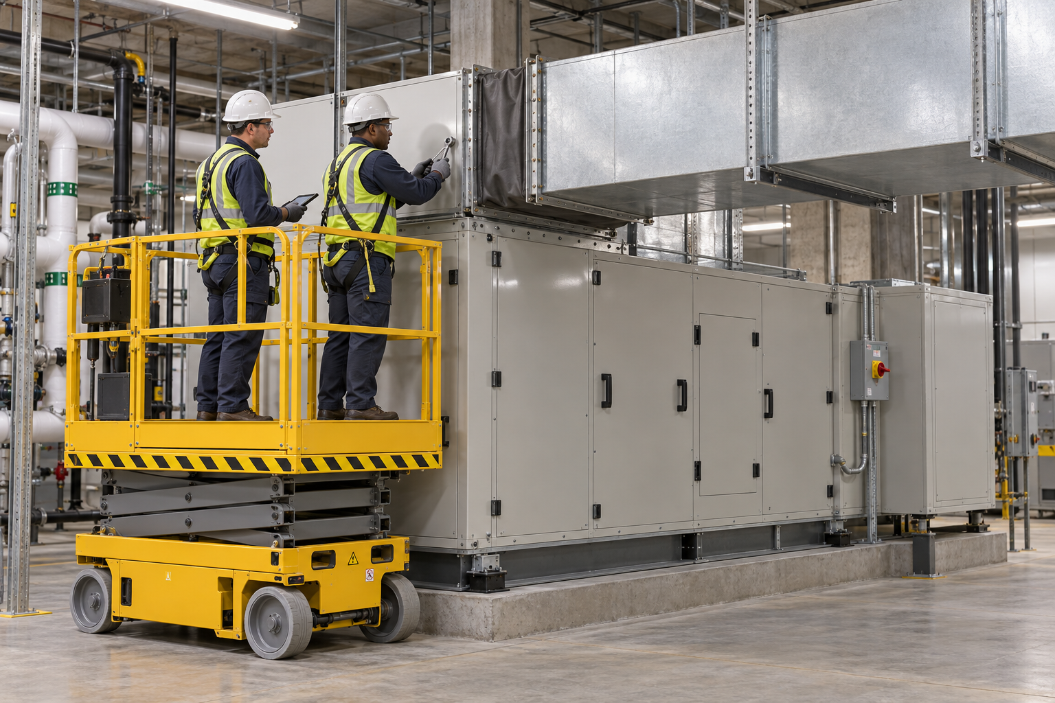
Retained AI-generated educational illustration from the source edition; not a real incident photograph, approved installation drawing or evidence of equipment suitability.
The scenario and record comparisons are fictional teaching examples, not records of real incidents, measurements, inspections, signatures or approvals.
| Item | Fictional scenario |
|---|---|
| Initial | A crew has set an air handler and is connecting the duct. |
| Change | The hanger does not align, so flange bolts are used to pull the duct toward the casing. |
| Failure | The casing and flexible connector receive duct weight and alignment force. |
| Outcome | The casing can distort, isolator loading can change and the joint can leak. |
| Barrier | Hold the connection; correct independent support and alignment, inspect the affected mounts and joint, then review commissioning separately. |
Why the controls matter
A sectional unit and a completed assembly have different weights and centers of gravity. Verify the authorized lifting configuration before rigging, including doors and loose internal components.
A level casing does not prove that all vibration isolators share the load. Check mounting orientation, contact, shipping restraints and the manufacturer sequence for releasing them.
A flexible duct connector accommodates intended movement; it does not replace duct hangers. Correct hanger location and alignment before connecting, and distinguish installation acceptance from permission to start the fan.
Decision sequence
| Step | Decision |
|---|---|
| Known | The hanger does not align, so flange bolts are used to pull the duct toward the casing. |
| Unknown | Actual condition, extent of damage and suitability of hands clear, mount load sharing remain to be established. |
| Hold | The casing and flexible connector receive duct weight and alignment force. |
| Evidence | Link hands clear, mount load sharing, base level, release stability, support sequence, workface cleanup to the affected equipment or work area. |
| Next | Hold the connection; correct independent support and alignment, inspect the affected mounts and joint, then review commissioning separately. |
5. Conditional decisions and common errors
| Condition | Action | Evidence | Proceed when |
|---|---|---|---|
| Combined lift | Verify authorized lifting configuration | Assembly weight, center and lifting drawing | Lifting points confirmed |
| Uneven mounts | Correct support and shipping restraints | Mount layout and contact checks | Load support confirmed |
| Forced flange | Realign independent duct supports | Hanger and connector inspection | External force removed |
| Fan startup | Complete a separate commissioning release | Guards, tools and restraint checklist | Startup conditions verified |
Similar appearance, different evidence
The scenario and record comparisons are fictional teaching examples, not records of real incidents, measurements, inspections, signatures or approvals.
| Comparison | Supported decision | Insufficient basis |
|---|---|---|
| Condition | Assembly weight, center and lifting drawing | Combined lift has not been resolved. |
| Evidence | Hanger and connector inspection | A photograph or a completed-looking task without the relevant inspection record. |
| Release | Startup conditions verified | Completion of one step does not release the excluded tasks in section 2. |
6. Roles and responsibilities
| Role | Responsibility |
|---|---|
| Work supervisor | Assign the task boundary, stop authority, interfaces and emergency communication for air handler lifting and duct connection. |
| Technical lead | Confirm Module and center; Foundation review; Route dimensions; Door swing. Resolve design and manufacturer limits before work. |
| Authorized crew | Apply Lifting configuration; Rigging inspection; Energy verification; Shipping restraints. Stop when the working arrangement changes. |
| Inspector / receiving lead | Review Hands clear; Mount load sharing; Base level; Release stability. Transfer Joint inspection; Guard fasteners; Restraint checklist; Commissioning scope. |
Role labels allocate responsibilities; they do not confer a legal qualification. Verify the competence, training and authority required for the actual task.
Record and handoff perspective
| Stage | Record controls | Verification |
|---|---|---|
| Plan route | 1. Record module and center2. Record foundation review3. Record route dimensions | 1. Foundation review2. Route dimensions3. Door swing |
| Rig and isolate | 1. Record lifting configuration2. Record rigging inspection3. Record energy verification | 1. Rigging inspection2. Energy verification3. Shipping restraints |
| Lift and move | 1. Record load balance2. Record radius and rating3. Record escape clearance | 1. Radius and rating2. Escape clearance3. Lift-zone control |
| Set modules | 1. Record hands clear2. Record mount load sharing3. Record base level | 1. Mount load sharing2. Base level3. Release stability |
| Correct defects | 1. Record support sequence2. Record workface cleanup3. Record start prevention | 1. Workface cleanup2. Start prevention3. Change drawing |
| Inspect and handoff | 1. Record joint inspection2. Record guard fasteners3. Record restraint checklist | 1. Guard fasteners2. Restraint checklist3. Commissioning scope |
7. Hold points and record comparison
| Hold point | Evidence before release | Actual record |
|---|---|---|
| HP-0 Start | Receive, lift, set and connect sectional air-handling units; verify foundations, vibration isolators, independently supported ductwork and the transition to commissioning. | |
| HP-1 Rig and isolate | Lifting configuration; Rigging inspection; Energy verification; Shipping restraints | |
| HP-2 Lift and move | Load balance; Radius and rating; Escape clearance; Lift-zone control | |
| HP-3 Connect duct | Hanger condition; Joint force and slack; Edge protection; Access location | |
| HP-4 Inspect and handoff | Joint inspection; Guard fasteners; Restraint checklist; Commissioning scope |
These are internal hold points, not issued permits. Recheck affected points after a change, fault or shift handoff; link the actual approval record.
Record comparison
The scenario and record comparisons are fictional teaching examples, not records of real incidents, measurements, inspections, signatures or approvals.
The boxes are static record prompts, not interactive or saved approvals. A tick does not establish suitability or permission to restart. Record the evidence, person, time and unresolved issues; retain the change history.
| Record | Insufficient | Record checklist |
|---|---|---|
| Plan route | "Checked" without target, criteria or result | □ Module and center□ Foundation review□ Route dimensions□ Door swing |
| Rig and isolate | "Checked" without target, criteria or result | □ Lifting configuration□ Rigging inspection□ Energy verification□ Shipping restraints |
| Set modules | "Checked" without target, criteria or result | □ Hands clear□ Mount load sharing□ Base level□ Release stability |
| Inspect and handoff | "Checked" without target, criteria or result | □ Joint inspection□ Guard fasteners□ Restraint checklist□ Commissioning scope |
8. Site checklist and emergency response
| Check | Result | Person / action |
|---|---|---|
| □ Plan route: Module and center | ||
| □ Prepare area: Platform and rails | ||
| □ Rig and isolate: Lifting configuration | ||
| □ Lift and move: Load balance | ||
| □ Set modules: Hands clear | ||
| □ Connect duct: Hanger condition | ||
| □ Correct defects: Support sequence | ||
| □ Inspect and handoff: Joint inspection | ||
| □ Emergency access and handoff restrictions |
Stop work
Hold lifting for unknown lifting points, center of gravity or support capacity. Stop duct connection for forced alignment, casing distortion, unstable supports or unisolated fan starting sources.
Emergency response
Stop from a safe location, exclude people from the affected danger zone and activate the site emergency plan. Call 911 for injury or immediate danger. Do not enter an unstable, energized or confined danger area for an improvised rescue; trained responders must control the specific energy and access hazards.
9. Sources and review limits
Public-source review: 2026-10-12. Official regulation pages and specific technical references are distinguished below; no agency or manufacturer has approved this content.
| Source | Reviewed scope and limitation |
|---|---|
| OSHA 29 CFR 1926.251 | Rigging identification, inspection and rated-load limits. |
| OSHA 29 CFR 1926.1417 | Applicable construction crane operating procedures and load capacity; not every hoist is within Subpart CC. |
| OSHA 29 CFR 1926.417 | Construction circuit controls and tags; site isolation must address every energy source. |
| Trane CLCH-SVX07D-EN | Official indexed lifting excerpt reviewed, not the full manual or the installed model. Section-specific lifting restrictions support checking the actual lifting unit. No model dimensions adopted. |
| OSHA State Plans | Official overview of federal and State Plan jurisdiction and differing public-sector coverage, checked 2026-10-12. Individual state rules require a site-specific check. |
No site measurements, equipment manuals for the actual installation, inspection records or signed technical approvals were supplied. Confirm the applicable requirements and actual product instructions before use; record each criterion with its units, source and equipment or work-area ID.
10. PDF guidance and FAQ
PDF A covers basic task controls; B focuses on technical failures; C covers supervision, records and handover. The article has eight stages with four items per main cell; each PDF has six key stages with three items per main cell. P/S/R/A, measurements, confirmations and signatures remain blank for actual site assessment.
Content group
jsa-ahu-ducting
Can section lifting eyes lift the whole assembled unit?
Only when the actual manufacturer lifting arrangement permits that assembly and load. Section ratings are not assembly ratings.
Does a flexible connector support the duct?
No. Provide the designed independent duct support and alignment.
When are shipping restraints removed?
Follow the actual manufacturer sequence for assembly, lifting and startup; record each retained or released restraint.
Does a completed duct joint authorize fan operation?
No. Verify isolation release, guards, personnel clearance and the separate commissioning plan.
Has a professional approved this JSA?
This reference material was written and revised with AI. It has not been verified or approved by a professional. Review by a suitably qualified professional and required site approval are necessary before field use.
11. Revision history and authorship
This reference material was written and revised with AI. It has not been verified or approved by a professional. Review by a suitably qualified professional and required site approval are necessary before field use.
Korean source created 2026-09-19. This US edition adapts the Korean source; earlier editorial revisions do not constitute professional approval of this edition.
| Date | Edition | Change | Review status |
|---|---|---|---|
| 2026-10-12 | 1.0 | US localization: preserve task judgments; replace Korean legal applicability with scoped US references. | AI editorial and output checks; no professional technical approval. |