Final tightening and piping connection can change the shaft position. A saved favourable display is not final evidence if the installation state later changes.
AI-generated reference material. It has not been verified or approved by a professional. Before use, a qualified person must review and adapt it to applicable Singapore requirements, the actual equipment and site, and approved safe work procedures.
1. Singapore legal and technical basis
Singapore WSH machinery controls require verified energy control before guards are removed or shafts are turned manually. The machine owner sets acceptance criteria from the actual motor, driven machine and coupling requirements. Manufacturer thermal-growth guidance is technical context and does not establish one universal cold target.
| Source category | Task application and limit |
|---|---|
| MOM - Risk management | Assess adjustment, support and operations interfaces. Official explanation of WSH Risk Management duties, not a complete consolidated statutory text. |
| WSHC - Safe Use of Machinery | Verify remote/process energy control and guard restoration. Official guidance with a summary of statutory duties; not a machine-specific safeguard design or full review of current legislation or paid standards. |
| SKF - Shaft alignment tool instructions | Distinguish actual cold target, thermal inputs and measurement reporting. Selected manufacturer instructions only, not the installed equipment manual. No universal tolerance or thermal-growth value is adopted; actual machine, coupling and instrument instructions govern. |
Use Singapore requirements and SI units. Manufacturer limits apply to the actual model. Foreign technical examples do not establish Singapore statutory duties. A job safety analysis or completed checklist is not a permit or approval.
2. Scope and required inputs
Included
Align an isolated motor and driven machine using laser or dial instruments, inspect base/soft foot, adjust with suitable shims and supports, remeasure the final state and hand over for separate startup.
Separate assessment
Powered rotation with guards open, live hand adjustment, invented thermal-growth targets and unassessed piping modification or operating vibration acceptance are excluded.
| Input | Evidence needed |
|---|---|
| Confirm targets and scope | Manufacturer criteria; Operating/work boundary; Temperature/growth basis; Machine/coupling ID |
| Isolate and verify stop | Motor/remote lockout; Process boundary; Residual motion/force; Safe access evidence |
| Measure initial condition | Hands/coupling clearance; Sensor/pipe clearance; Instrument safety class; Dimensions/angles/readings |
| Restore and transfer | Guard/fasteners; Tool/sensor removal; Alignment/temp records; Startup scope/receiver |
Select task-appropriate eye, hand, foot, skin and hearing protection from the exposure assessment. Where respiratory protection is necessary, use the applicable respiratory-protection program; PPE does not replace isolation, guarding, support or ventilation.
Singapore application
Record machine and coupling IDs, fixed/moving machine, temperature state and the source of the cold target. For a laser instrument use its actual safety instructions and verified setup. Manual rotation must follow the isolated-machine method; exposed powered jogging is outside this task.
3. Eight-stage JSA
| Job stage | Hazards and effects | Failure factors | Controls | Site verification | P | S | R | A |
|---|---|---|---|---|---|---|---|---|
| 1. Confirm targets and scope | 1. Vibration damage2. Unexpected rotation3. Pipe strain4. Wrong operating release | 1. Target unknown2. Operations not coordinated3. Thermal growth ignored4. Machine ID wrong | 1. Match equipment targets2. Define work boundary3. Separate cold/hot basis4. Identify machine/coupling | 1. Manufacturer criteria2. Operations work boundary3. Temperature/growth basis4. Machine/coupling ID | ||||
| 2. Isolate and verify stop | 1. Motor starts2. Backflow turns shaft3. Coasting contact4. Guard-removal injury | 1. Remote source missed2. Process not isolated3. Standstill unverified4. Control stop only | 1. Isolate startup sources2. Control process forces3. Verify full standstill4. Open guard after verification | 1. Motor/remote lockout2. Process boundary3. Residual motion/force4. Safe access evidence | ||||
| 3. Check base and instruments | 1. False readings2. Base distortion3. Sensor falls4. Shim cuts | 1. Soft foot ignored2. Fasteners loose3. Sensor mount weak4. Dirty/damaged shims | 1. Assess foot contact2. Inspect base/anchors3. Verify instrument/mounts4. Use clean suitable shims | 1. Foot contact/distortion2. Support/bolt state3. Instrument/mount check4. Shim stack/condition | ||||
| 4. Measure initial condition | 1. Manual-rotation pinch2. Sensor collision3. Laser eye exposure4. Wrong data interpretation | 1. Rotation improvised2. Interference missed3. Beam viewed directly4. Dimensions entered wrong | 1. Use instructed manual method2. Check full sensor travel3. Follow laser safety instructions4. Record exact measurement state | 1. Hands/coupling clearance2. Sensor/pipe clearance3. Instrument safety class4. Dimensions/angles/readings | ||||
| 5. Shim and move safely | 1. Foot crush2. Machine shifts3. Shim ejects4. Shaft forced sideways | 1. Foot lifted unsupported2. Adjuster overloaded3. Hand pushes shim4. Coupling pulls alignment | 1. Support designated lift points2. Move within planned limits3. Use shim insertion tools4. Avoid forced shaft alignment | 1. Support stability2. Adjuster/movement3. Hand/shim position4. Coupling constraint | ||||
| 6. Remeasure final state | 1. Alignment shifts on tightening2. Pipe strain3. Instrument left attached4. Wrong thermal target | 1. Final check omitted2. Piping effect ignored3. Sensor not counted4. Cold/hot limits mixed | 1. Remeasure after tightening2. Check connected piping effects3. Remove instruments safely4. Compare correct targets | 1. Final offset/angle2. Soft-foot/piping state3. Instrument/tool count4. Temperature/target/result | ||||
| 7. Hold unstable results | 1. Stored force releases2. Foot/base damage3. Unexpected rotation4. Repeated wrong correction | 1. Shims added blindly2. Bolts force position3. Isolation disturbed4. Instrument fault ignored | 1. Resolve measurement cause2. Review base/contact3. Reverify isolation4. Repeat consistent measurements | 1. Cause/correction2. Foot/base findings3. Energy/force state4. Measurement repeatability | ||||
| 8. Restore and transfer | 1. Rotating contact2. Sensor ejection3. Operating vibration4. Unauthorised start | 1. Guard absent2. Tools remain3. Results not transferred4. Startup release omitted | 1. Restore complete guarding2. Reconcile tools/sensors3. Transfer alignment conditions4. Authorise separate startup | 1. Guard/fasteners2. Tool/sensor removal3. Alignment/temp records4. Owner startup release |
P/S/R/A and actual measurements, checks, names and signatures remain blank for the site assessment. A score cannot waive a required control.
4. Hypothetical scenario and failure mechanisms
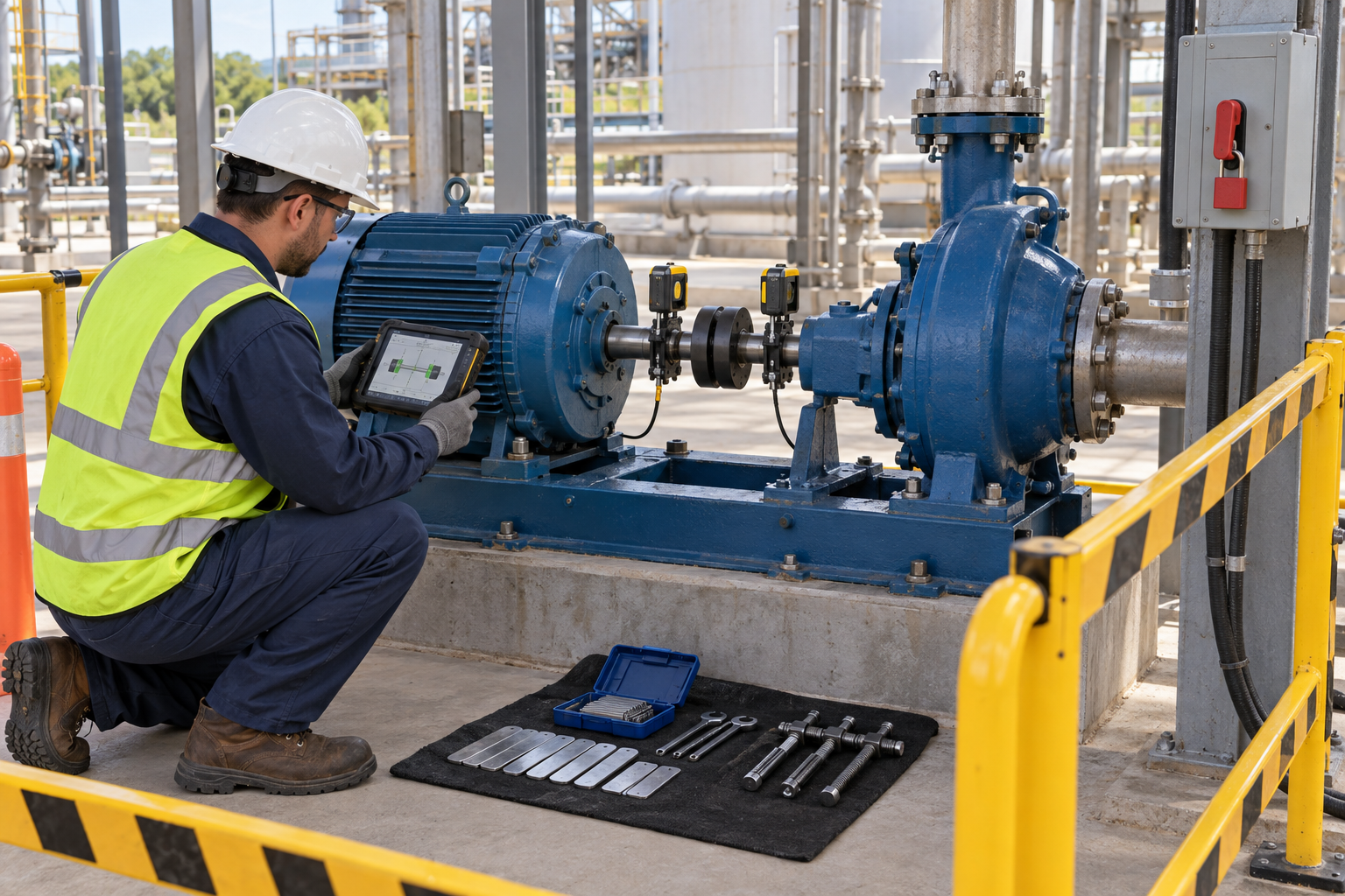
The retained illustration is an AI-generated educational image from the Korean source. It is not an actual incident photograph, approved drawing, equipment certification or proof that the depicted arrangement is safe.
Soft foot is uneven or unsuitable foot-to-base contact that can distort or move the machine when bolts are tightened. Dirt, damaged shims and angled contact need cause correction rather than blind addition of shim thickness.
A favorable display is only useful when sensor mounting, dimensions, rotation positions, bolt state and temperature are correct and repeatable. Investigate changing readings before moving the machine again.
Piping connection and final bolt tightening can change shaft position. Do not pull the machine into alignment with coupling or pipe bolts; resolve the cause and check the completed installation state.
Cold targets can differ from operating targets because of thermal growth. Alignment acceptance, instrument removal, guard restoration and startup authorisation remain separate checks.
Hypothetical decision example
Hypothetical example: initial cold readings are saved, then piping is forced into place and foot bolts are retightened. The initial result is proposed as final. Handover is held while pipe strain, foot contact and alignment are reassessed in the final condition.
The example is fictional; no incident, measurement, inspection or approval is asserted.
Task flow: Confirm targets and scope → Isolate and verify stop → Check base and instruments → Measure initial condition → Shim and move safely → Remeasure final state → Hold unstable results → Restore and transfer
5. Hold and proceed decisions
| Condition | Action | Evidence | Proceed when |
|---|---|---|---|
| Readings vary | Hold adjustment | Mounts, inputs and repeated readings | Measurement repeatable |
| Soft foot present | Correct contact cause | Foot/shim/base evidence | Foot condition verified |
| Piping state changes | Resolve strain; remeasure | Final bolt/piping/temperature record | Final alignment accepted |
| Ready for startup | Remove tools; restore guards | Result limits and startup plan | Handover authorised |
Similar observation, different conclusion
| Observation | Supported conclusion | What remains unresolved |
|---|---|---|
| Display within target | One reading meets entered target | Inputs and final condition unproved |
| Cold alignment accepted | Cold condition assessed | Operating thermal/vibration checks separate |
6. Roles and supervision
| Role | Responsibility |
|---|---|
| Work supervisor | Coordinate confirm targets and scope, affected operations, stop signals and stage transitions. |
| Technical/equipment reviewer | Verify Manufacturer criteria, Operating/work boundary, actual instructions and unresolved technical limits. |
| Task crew | Apply the stated controls, report changes and keep actual checks and signatures factual. |
| Inspector/test lead | Connect Final offset/angle, Soft-foot/piping state to the required acceptance criteria. |
| Receiving authority | Accept the recorded restrictions, Alignment/temp records, Startup scope/receiver, and follow-up ownership. |
These are responsibility examples, not invented statutory credentials. Verify actual competence, training and authority for the assigned work.
Supervision and handover controls
| Stage | Management controls | Evidence |
|---|---|---|
| Plan review | 1. Assign technical owner2. Close task-specific questions3. Match equipment targets | 1. Manufacturer criteria2. Operating/work boundary3. Machine/coupling ID |
| Competence | 1. Verify required competence2. Assign stop authority3. Isolate startup sources | 1. Motor/remote lockout2. Training and task briefing3. Safe access evidence |
| Prestart evidence | 1. Inspect actual equipment2. Link evidence to this stage3. Use instructed manual method | 1. Hands/coupling clearance2. Sensor/pipe clearance3. Dimensions/angles/readings |
| Change control | 1. Stop and secure the area2. Review affected controls3. Resolve measurement cause | 1. Cause/correction2. Foot/base findings3. Measurement repeatability |
| Shift handover | 1. Identify remaining restrictions2. Confirm receiving responsibility3. Restore complete guarding | 1. Guard/fasteners2. Tool/sensor removal3. Startup scope/receiver |
| Closeout | 1. Record defect disposition2. Archive factual evidence3. Restore complete guarding | 1. Guard/fasteners2. Tool/sensor removal3. Startup scope/receiver |
Singapore application
The maintenance lead accepts repeatable final-state readings after foot-bolt tightening and piping connection. The machine owner separately accepts removal of sensors and tools, guard restoration and the startup scope. Subsequent operating vibration and thermal assessment remain separate from the cold-alignment record.
7. Hold points and record quality
| Hold point | Evidence before release | Actual record |
|---|---|---|
| HP-0 Start | Align an isolated motor and driven machine using laser or dial instruments, inspect base/soft foot, adjust with suitable shims and supports, remeasure the final state and hand over for separate startup. | |
| HP-1 Isolate and verify stop | Motor/remote lockout; Process boundary; Residual motion/force; Safe access evidence | |
| HP-2 Measure initial condition | Hands/coupling clearance; Sensor/pipe clearance; Instrument safety class; Dimensions/angles/readings | |
| HP-3 Hold unstable results | Cause/correction; Foot/base findings; Energy/force state; Measurement repeatability | |
| HP-4 Restore and transfer | Guard/fasteners; Tool/sensor removal; Alignment/temp records; Startup scope/receiver |
Hold points are internal evidence gates. They do not establish that a statutory permit exists or has been approved. Recheck affected gates after changes, faults and shift handover.
Record comparison - hypothetical templates
The 16 boxes below identify record elements, not completed checks or approvals. They are static symbols. Link equipment/location, date, actual findings and the separate record reference; preserve unresolved items.
| Record | Insufficient entry | Required record elements |
|---|---|---|
| Confirm targets and scope | "Checked" without supporting facts | □ Manufacturer criteria□ Operating/work boundary□ Temperature/growth basis□ Machine/coupling ID |
| Check base and instruments | "Checked" without supporting facts | □ Foot contact/distortion□ Support/bolt state□ Instrument/mount check□ Shim stack/condition |
| Shim and move safely | "Checked" without supporting facts | □ Support stability□ Adjuster/movement□ Hand/shim position□ Coupling constraint |
| Hold unstable results | "Checked" without supporting facts | □ Cause/correction□ Foot/base findings□ Energy/force state□ Measurement repeatability |
8. Pre-work checks and emergency response
| Check required | Result | Checker/action |
|---|---|---|
| Confirm targets and scope: Manufacturer criteria | ||
| Isolate and verify stop: Motor/remote lockout | ||
| Check base and instruments: Foot contact/distortion | ||
| Measure initial condition: Hands/coupling clearance | ||
| Shim and move safely: Support stability | ||
| Remeasure final state: Final offset/angle | ||
| Hold unstable results: Cause/correction | ||
| Restore and transfer: Guard/fasteners |
Stop work
Hold guard removal for unverified startup/backflow isolation, standstill or manual rotation method. Stop adjustment for unstable feet, nonrepeatable readings, forced piping, base distortion or unknown targets.
Emergency response
Stop manual movement and keep hands clear of couplings, machine feet and shifting supports. Maintain isolation and stabilize the machine with the approved method before rescue or recovery. Do not jog the motor or loosen load-bearing supports to release a trapped part. Contact the site emergency responders for serious crushing or entanglement injury and tell responders the equipment, isolation and support state.
9. Sources and review limits
Public-source review: 14 October 2026. Only the material and limits identified below were reviewed.
| Source | Reviewed material | Task application |
|---|---|---|
| MOM - Risk management | Responsibilities; routine and non-routine work; hierarchy of control and risk assessment team. Official explanation of WSH Risk Management duties, not a complete consolidated statutory text. | Assess adjustment, support and operations interfaces. |
| WSHC - Safe Use of Machinery | Printed pages 4, 27, 37-39: dangerous parts, maintenance training, hazardous-energy isolation, verification, group/shift continuity and restoration. Official guidance with a summary of statutory duties; not a machine-specific safeguard design or full review of current legislation or paid standards. | Verify remote/process energy control and guard restoration. |
| SKF - Shaft alignment tool instructions | Indexed English page 7, target values, report information and thermal growth input sections. Selected manufacturer instructions only, not the installed equipment manual. No universal tolerance or thermal-growth value is adopted; actual machine, coupling and instrument instructions govern. | Distinguish actual cold target, thermal inputs and measurement reporting. |
Selected public official sources were reviewed on 14 October 2026 within the recorded scope. No full consolidated legal audit, paid Singapore Standard, actual model manual, site inspection, engineering calculation or professional approval is claimed. Verify current detailed requirements and actual equipment/site records before use.
AI-generated reference material. It has not been verified or approved by a professional. Before use, a qualified person must review and adapt it to applicable Singapore requirements, the actual equipment and site, and approved safe work procedures.
10. PDF use and frequently asked questions
PDF A summarizes core controls; B emphasizes technical failures; C covers supervision, records and handover. Each uses six stages from or aligned with the eight-stage body. All actual risk, measurement, check and signature fields are blank. Use a separate linked record where more space is needed.
Does a green laser display finish the job?
No. Verify inputs, repeatability, final connection state and the actual equipment target, then restore guarding.
Is more shim always the soft-foot correction?
No. Identify contamination, damaged contact, distortion or angled foot conditions and remeasure after correction.
Should all cold targets be zero?
Use the approved equipment thermal-growth basis and operating requirements.
Can the motor be jogged for measurement?
Powered rotation with exposed couplings is outside this scope. Use the instructed manual method under verified energy control.
Has a professional approved this JSA?
This is reference content written and revised with AI. It has not been verified or approved by a professional. Review by a suitably qualified professional and required site authorisation are necessary before use.
Singapore application
Read A, B and C together with all eight JSA stages and the approved work procedure. The sheets are complementary extracts, not separate work authorisations.
11. Authorship and revision history
AI-generated reference material. It has not been verified or approved by a professional. Before use, a qualified person must review and adapt it to applicable Singapore requirements, the actual equipment and site, and approved safe work procedures.
| Date / edition | Authorship and scope | Professional approval |
|---|---|---|
| 2026-09-20 / Korean source | Original topic and educational illustration retained as references. Source content is unchanged. | Not asserted |
| 14 October 2026 / Singapore 1.0 | Added Singapore isolation/restoration responsibility and bounded manufacturer thermal-target guidance. | Not performed |
Source topic: https://smartjsabridge.com/ko/case-study/jsa-shaft-alignment