Identify every power, control and external feed before isolation. Plan the separate functional-test state and final restoration so a successful local test cannot conceal retained forces, temporary links or unexpected remote commands.
AI-generated reference material. It has not been verified or approved by a professional. Before use, a qualified person must review and adapt it to applicable Singapore requirements, the actual equipment and site, and approved safe work procedures.
1. Singapore legal and technical basis
Singapore electrical wiring work must be assigned to the appropriate Licensed Electrical Worker arrangements. WSH machinery controls also require safe isolation of connected machines and stored energy. An electrical dead check and a machine functional test establish different conditions; this document does not authorise live wiring or automatic operation.
| Source category | Task application and limit |
|---|---|
| MOM - Risk management | Assess changing electrical and machine states. Official explanation of WSH Risk Management duties, not a complete consolidated statutory text. |
| EMA - Engaging Licensed Electrical Workers | Confirm the appropriate electrical-work responsibility and licence scope. Installation, repair or modification of wiring and supply equipment is distinguished from routine operation of an intact appliance. Licence scope must match the installation. |
| WSHC - Safe Use of Machinery | Coordinate isolation, group work and controlled machine restoration. Official guidance with a summary of statutory duties; not a machine-specific safeguard design or full review of current legislation or paid standards. |
Use Singapore requirements and SI units. Manufacturer limits apply to the actual model. Foreign technical examples do not establish Singapore statutory duties. A job safety analysis or completed checklist is not a permit or approval.
2. Scope and required inputs
Included work
Identification, isolation, power/control/protective-earth wiring and de-energized checks in a motor control centre, followed by preparation for separately authorised functional testing and documented restoration.
Separate assessment
Energized wiring, internal live maintenance, improvised safety-interlock bypass and unapproved motor or automatic-operation tests are excluded.
| Required input | Evidence to obtain |
|---|---|
| Identify circuits and machine | Drawing and motor IDs; External supplies; Safety functions; Test and restoration plan |
| Isolate and verify | Locks and source points; Model discharge basis; Test method and result; Machine safe state |
| Inspect units and space | Unit identity and rating; Support and condition; Tool inventory; Adjacent boundary |
| Wire power and earth | Crimp and terminal type; Fastening evidence; Phase and earth checks; Bend and strain relief |
Singapore application
Name the responsible LEW and machine owner before wiring begins. Agree which person controls external supplies, control-circuit injections and remote operating modes. Actual drawings and manufacturer discharge/test instructions govern; a generic waiting time is not proof of discharge.
3. Eight-stage JSA
| Job stage | Hazards and effects | Failure factors | Controls | Site verification | P | S | R | A |
|---|---|---|---|---|---|---|---|---|
| 1. Identify circuits and machine | 1. Wrong motor motion2. Remote start3. Control backfeed4. Protection failure | 1. Drawing outdated2. Inputs omitted3. Auxiliary feed missed4. Settings unreviewed | 1. Match drawing revisions2. Trace every source3. Define machine boundary4. Plan test authority | 1. Drawing and motor IDs2. External supplies3. Safety functions4. LEW and test authority | ||||
| 2. Isolate and verify | 1. Electric shock2. Stored-energy arc3. Machine movement4. False safe state | 1. Display trusted2. DC energy remains3. Mechanical energy missed4. Tester unsuitable | 1. Apply source isolation2. Follow discharge method3. Control machine energy4. Use qualified verification | 1. Locks and source points2. Model discharge basis3. Test method and result4. Machine safe state | ||||
| 3. Inspect units and space | 1. Unit drop2. Insulation damage3. Debris short4. Adjacent live contact | 1. Unit unsupported2. Damage overlooked3. Metal scraps left4. Boundary unclear | 1. Support removable units2. Check ratings and damage3. Control tools and debris4. Protect adjacent circuits | 1. Unit identity and rating2. Support and condition3. Tool inventory4. Adjacent boundary | ||||
| 4. Wire power and earth | 1. Hot terminal2. Wrong rotation3. Lost earth path4. Cable damage | 1. Crimp mismatch2. Phase ID wrong3. Earth omitted4. Bend or strain excessive | 1. Use specified terminals2. Identify phases3. Verify protective earth4. Provide cable support | 1. Crimp and terminal type2. Fastening evidence3. Phase and earth checks4. Bend and strain relief | ||||
| 5. Wire controls and signals | 1. Unexpected start2. Safety failure3. Signal interference4. External voltage | 1. Terminal confused2. Bypass improvised3. Routing mixed4. Common misunderstood | 1. Match terminal schedule2. Preserve safety design3. Segregate signal routes4. Follow shield scheme | 1. Terminal and wire IDs2. Safety-circuit checks3. Route and separation4. Shield and common basis | ||||
| 6. Perform dead checks | 1. Electronics damage2. Wrong test conclusion3. Tool-caused short4. Cover omitted | 1. Test voltage wrong2. Continuity overclaimed3. Tools uncounted4. Guard left off | 1. Use approved test method2. Separate function testing3. Reconcile tools4. Restore required covers | 1. Test connections2. Results and limits3. Electronics protection4. Tools and covers | ||||
| 7. Control functional test | 1. Remote machine motion2. Arc exposure3. Unsafe correction4. False protective action | 1. People not clear2. Test boundary absent3. Live correction attempted4. Force untracked | 1. Authorise each test state2. Clear machine envelope3. Re-isolate for changes4. Log temporary overrides | 1. Test state and authority2. Expected actual response3. Force and jumper log4. Renewed isolation | ||||
| 8. Restore and hand over | 1. Automatic start2. Protection bypass3. Wrong settings4. Uninformed operator | 1. Normal mode assumed2. Jumper remains3. Version not restored4. Handover absent | 1. Use restoration sequence2. Reconcile temporary items3. Verify approved settings4. Obtain operation release | 1. Restoration inventory2. Normal-mode checks3. Guard and people status4. Joint restoration authority |
P/S/R/A and actual measurements, checks, names and signatures remain blank for the site assessment. A score cannot waive a required control.
4. Hypothetical scenario and failure mechanisms
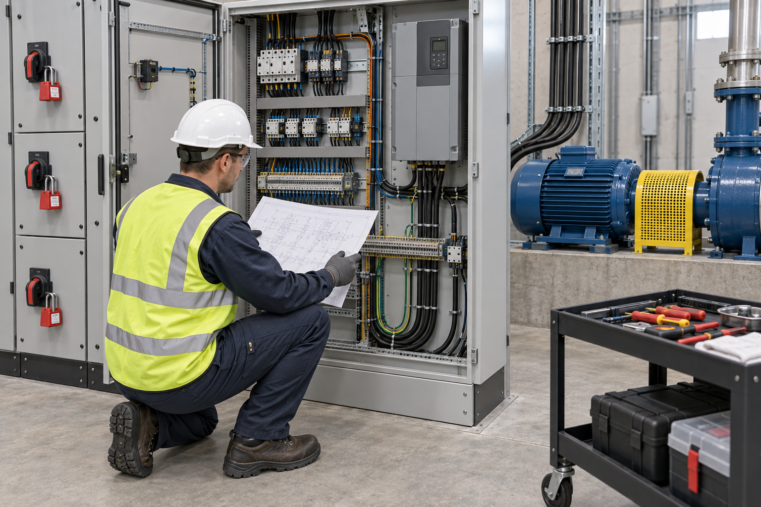
This illustration provides educational context. It is not an actual incident photograph or evidence of equipment suitability; any AI-generated depiction is illustrative only.
The scenario and record comparisons are fictional teaching examples, not records of real incidents, measurements, inspections, signatures or approvals.
| Stage | Fictional situation |
|---|---|
| Initial situation | A fictional crew completes a successful local motor test. |
| Changed condition | The next shift requests automatic operation. |
| Failure path | Temporary forced values and remote start inputs have not been reconciled. |
| Possible outcome | A machine could start unexpectedly or operate without an intended protective function. |
| Prevention barrier | Hold automatic release, reconcile every temporary change, restore the approved configuration and verify the required states with machinery safeguards and personnel clear. |
Failure mechanisms
A dark display does not prove that all power is absent. Auxiliary supplies, externally powered control terminals, stored DC-link energy and connected machinery require identification and a qualified verification procedure. Follow the actual model discharge instructions; elapsed time alone is not proof.
Point-to-point continuity is not a functional test of a safety circuit, motor direction or every automatic state. Insulation-test connections and voltage must suit the equipment; connected drives and electronics may require disconnection under their instructions.
Temporary jumpers, forced logic values and changed settings need an inventory and an approved restoration sequence. Removing them indiscriminately can itself cause movement. Each energized test needs a cleared machine boundary and authority; corrections require renewed isolation and verification.
Work sequence: Identify circuits and machine → Isolate and verify → Inspect units and space → Wire power and earth → Wire controls and signals → Perform dead checks → Control functional test → Restore and hand over. This is a teaching flow, not a device drawing or a complete operating procedure.
Singapore application
Record test forces, temporary links and remote-command restrictions in one controlled list. Verify their required final state before transfer to the operating team; a correct local indication is insufficient evidence of complete restoration.
5. Hold and proceed decisions
| Situation | Required action | Evidence | Proceed when |
|---|---|---|---|
| Auxiliary source unknown | Hold wiring | Supply tracing and isolation record | All sources controlled |
| Insulation test proposed | Check equipment compatibility | Model, connections and test method | Method accepted |
| Test result differs | Stop test and isolate | Expected versus actual response | Correction verified |
| Automatic mode requested | Reconcile temporary changes | Forces, jumpers and safeguards | Operation authorised |
Similar observations, different decisions
The scenario and record comparisons are fictional teaching examples, not records of real incidents, measurements, inspections, signatures or approvals.
| Observation | Insufficient conclusion | Required distinction |
|---|---|---|
| Display off | Control indication | Electrical safe state unproved |
| Continuity passes | Circuit path checked | Safety function unproved |
| Local test passes | One operating state | Automatic release separate |
6. Roles and supervision
| Role | Responsibility |
|---|---|
| Work supervisor | Confirm drawing and motor ids and the task scope, resources, interfaces and stop authority. |
| Qualified technical reviewer | Review locks and source points, model limits, compatibility and unresolved technical conditions within assigned competence. |
| Work crew | Apply the listed controls, report changes and stop when evidence or safeguards are missing. |
| Inspector / assessor | Record actual terminal and wire ids and other relevant checks; do not mark unverified conditions as accepted. |
| Handover authority | Reconcile restoration inventory, restrictions and outstanding actions before the next task. Role labels do not establish a legal credential. |
Supervision and handover focus
| Stage | Management action | Evidence |
|---|---|---|
| Identify circuits and machine | 1. Record drawing and motor ids2. Record external supplies3. Record safety functions | 1. Drawing and motor IDs2. External supplies3. Safety functions |
| Isolate and verify | 1. Record locks and source points2. Record model discharge basis3. Record test method and result | 1. Locks and source points2. Model discharge basis3. Test method and result |
| Wire power and earth | 1. Record crimp and terminal type2. Record fastening evidence3. Record phase and earth checks | 1. Crimp and terminal type2. Fastening evidence3. Phase and earth checks |
| Wire controls and signals | 1. Record terminal and wire ids2. Record safety-circuit checks3. Record route and separation | 1. Terminal and wire IDs2. Safety-circuit checks3. Route and separation |
| Control functional test | 1. Record test state and authority2. Record expected actual response3. Record force and jumper log | 1. Test state and authority2. Expected actual response3. Force and jumper log |
| Restore and hand over | 1. Record restoration inventory2. Record normal-mode checks3. Record guard and people status | 1. Restoration inventory2. Normal-mode checks3. Guard and people status |
Singapore application
The electrical team accepts wiring and test records within its scope. The machine owner accepts the restored guarding, safety functions and operating modes. The designated restoration authority reconciles both records and personnel clearance before releasing the installation.
7. Hold points and record quality
| Hold point | Evidence before release | Actual approval |
|---|---|---|
| HP-0 Scope | Identification, isolation, power/control/protective-earth wiring and de-energized checks in a motor control centre, followed by preparation for separately authorised functional testing and documented restoration. | |
| HP-1 Isolate and verify | Locks and source points; Model discharge basis; Test method and result; Machine safe state | |
| HP-2 Wire power and earth | Crimp and terminal type; Fastening evidence; Phase and earth checks; Bend and strain relief | |
| HP-3 Control functional test | Test state and authority; Expected actual response; Force and jumper log; Renewed isolation | |
| HP-4 Restore and hand over | Restoration inventory; Normal-mode checks; Guard and people status; Recipient and authority |
Hold points are internal project checks. They are not universal statutory permits and do not grant work permission. Reassess after defects, changed conditions and shift changes.
Record comparison
The scenario and record comparisons are fictional teaching examples, not records of real incidents, measurements, inspections, signatures or approvals.
The boxes are static record prompts, not interactive or saved approvals. A tick does not establish suitability or permission to restart. Record the evidence, person, time and unresolved issues; retain the change history.
| Record | Insufficient record | Record checklist |
|---|---|---|
| Identify circuits and machine | Only marked “OK” | □ Drawing and motor IDs□ External supplies□ Safety functions□ Test and restoration plan |
| Wire power and earth | Only marked “OK” | □ Crimp and terminal type□ Fastening evidence□ Phase and earth checks□ Bend and strain relief |
| Control functional test | Only marked “OK” | □ Test state and authority□ Expected actual response□ Force and jumper log□ Renewed isolation |
| Restore and hand over | Only marked “OK” | □ Restoration inventory□ Normal-mode checks□ Guard and people status□ Recipient and authority |
8. Pre-work checks and emergency response
| Site check | Actual result | Person / action |
|---|---|---|
| Identify circuits and machine: Drawing and motor IDs; External supplies; Safety functions; Test and restoration plan | ||
| Isolate and verify: Locks and source points; Model discharge basis; Test method and result; Machine safe state | ||
| Inspect units and space: Unit identity and rating; Support and condition; Tool inventory; Adjacent boundary | ||
| Wire power and earth: Crimp and terminal type; Fastening evidence; Phase and earth checks; Bend and strain relief | ||
| Wire controls and signals: Terminal and wire IDs; Safety-circuit checks; Route and separation; Shield and common basis | ||
| Perform dead checks: Test connections; Results and limits; Electronics protection; Tools and covers | ||
| Control functional test: Test state and authority; Expected actual response; Force and jumper log; Renewed isolation | ||
| Restore and hand over: Restoration inventory; Normal-mode checks; Guard and people status; Recipient and authority |
Stop work
Hold work for unidentified supplies, uncertain stored energy, missing electrical or machine isolation, unsuitable test equipment or unapproved wiring changes. Stop any unexpected response; automatic operation remains on hold until restoration and authorisation are complete.
Emergency response
Keep people clear of exposed circuits and moving machinery. Use the established emergency isolation and response plan; do not touch a person or equipment still exposed to electrical energy. Qualified personnel secure the condition before rescue, correction or investigation.
9. Sources and review limits
Public-source review: 14 October 2026. Only the material and limits identified below were reviewed.
| Source | Reviewed material | Task application |
|---|---|---|
| MOM - Risk management | Responsibilities; routine and non-routine work; hierarchy of control and risk assessment team. Official explanation of WSH Risk Management duties, not a complete consolidated statutory text. | Assess changing electrical and machine states. |
| EMA - Engaging Licensed Electrical Workers | Overview, examples of wiring and circuit work, licence classes and verification of valid licences. Installation, repair or modification of wiring and supply equipment is distinguished from routine operation of an intact appliance. Licence scope must match the installation. | Confirm the appropriate electrical-work responsibility and licence scope. |
| WSHC - Safe Use of Machinery | Printed pages 4, 27, 37-39: dangerous parts, maintenance training, hazardous-energy isolation, verification, group/shift continuity and restoration. Official guidance with a summary of statutory duties; not a machine-specific safeguard design or full review of current legislation or paid standards. | Coordinate isolation, group work and controlled machine restoration. |
Selected public official sources were reviewed on 14 October 2026 within the recorded scope. No full consolidated legal audit, paid Singapore Standard, actual model manual, site inspection, engineering calculation or professional approval is claimed. Verify current detailed requirements and actual equipment/site records before use.
AI-generated reference material. It has not been verified or approved by a professional. Before use, a qualified person must review and adapt it to applicable Singapore requirements, the actual equipment and site, and approved safe work procedures.
10. PDF use and frequently asked questions
PDF A covers basic task controls; B focuses on technical failures; C covers supervision, records and handover. The article has eight stages with four items per main cell; each PDF has six key stages with three items per main cell. P/S/R/A, measurements, confirmations and signatures remain blank for actual site assessment.
PDFs are complementary six-stage extracts. Apply all eight body stages and the actual equipment/site procedure.
Can a stop button isolate the MCC?
No. Identify and isolate all relevant sources using the applicable procedure and qualified verification.
Can all forced values simply be deleted?
Use the approved restoration sequence, inventory and machine safeguards; an uncontrolled change can initiate motion.
Does a successful manual test release automatic operation?
No. Verify the approved configuration and required remote, protective and automatic states before the designated authority releases operation.
Has a professional verified or approved this document?
No. Public sources and editorial, layout and consistency checks were reviewed using AI. No site inspection or professional technical approval has been performed. Obtain appropriate professional review before use.
Singapore application
Read A, B and C together with all eight JSA stages and the approved work procedure. The sheets are complementary extracts, not separate work authorisations.
11. Authorship and revision history
AI-generated reference material. It has not been verified or approved by a professional. Before use, a qualified person must review and adapt it to applicable Singapore requirements, the actual equipment and site, and approved safe work procedures.
| Date / edition | Authorship and scope | Professional approval |
|---|---|---|
| 2026-09-20 / Korean source | Original topic and educational illustration retained as references. Source content is unchanged. | Not asserted |
| 14 October 2026 / Singapore 1.0 | Added Singapore licensed electrical responsibility and combined machine/electrical release with documented temporary-force removal. | Not performed |
Source topic: https://smartjsabridge.com/ko/case-study/jsa-mccpanel-wiring