Establish the fill/test boundary, full-water support load and vent path before starting the pump. Filling completion is an input to the separate pressure-test review, and neither a stopped pump nor one zero gauge proves all trapped sections are safe.
AI-generated reference material. It has not been verified or approved by a professional. Before use, a qualified person must review and adapt it to applicable Singapore requirements, the actual equipment and site, and approved safe work procedures.
1. Singapore legal and technical basis
Singapore WSH risk management covers temporary supports, lifting and stored energy during filling. The separate pressure-test design and release remain outside this scope. PUB Written Approval applies where trade premises discharge trade effluent to the public sewer; confirm the actual collection and disposal route before filling rather than assuming any nearby drain is suitable.
| Source category | Task application and limit |
|---|---|
| MOM - Risk management | Assess temporary assemblies, changing support loads and foreseeable test backfeed. Official explanation of WSH Risk Management duties, not a complete consolidated statutory text. |
| WSHC - Planning a Lift | Plan pipe unloading and rated gear before removing bundle restraint. Official guidance. The plan and permit requirements must be determined for the actual lifting operation; this page is not a universal permit rule. |
| UK HSE - Pressure testing GS4 | Use foreign technical lessons on connector integrity, venting and stored-energy segregation within this filling scope. Foreign technical guidance only. UK duties, enclosure thickness examples and test values are not adopted as Singapore requirements. This article covers filling, not the separate pressure test. |
| PUB - Written Approval for trade effluent | Verify the public-sewer approval and conditions if the collected water is trade effluent; determine other disposal routes separately. Decision-flow image not reviewed. Actual effluent classification, discharge quality and approval conditions require separate site verification; sewer approval is not open-drain permission. |
Use Singapore requirements and SI units. Manufacturer limits apply to the actual model. Foreign technical examples do not establish Singapore statutory duties. A job safety analysis or completed checklist is not a permit or approval.
2. Scope and required inputs
Included scope
Installation and controlled water filling of an identified industrial piping system using temporary rigid pipe and hose. Record the pump, route, medium, temperature, elevation, component ratings and intended test interface. Keep people outside the assessed jet, whip and falling-object zones.
Separate review
High-pressure testing, pneumatic testing, leak repair under pressure, hot or hazardous-fluid service and vessel entry require separate engineered procedures. Completing this filling checklist does not authorize raising pressure to the test value.
| Required input | What to verify |
|---|---|
| Define fill boundary | Boundary drawing · Component register · Pump duty data · Isolation plan |
| Route and support | Load calculation · Support locations · Ground assessment · Access route |
| Assemble joints | Joint component IDs · Torque procedure · Tool calibration · Assembly record |
| Connect hoses | Assembly rating · Lock engagement · Restraint instructions · Hose inspection |
| Line up and vent | Valve lineup · Vent routing · Gauge/relief data · Communication test |
| Stop and hand over | Isolation record · Zero-pressure evidence · Drain condition · Separate test release |
No actual pump, hose manual or paid code text has been reviewed. Support spacing, restraint selection, vent capacity, allowable fill rate, pressure limits and valve timing require the actual design and manufacturer data. There is no universal 1 m/s limit, L/500 support rule, cable safety factor or 30/60/100 torque sequence established by this article. At handover, distinguish draining an isolated temporary branch for disconnection from emptying the test object. Retain water in the test object as required by its separate test plan. Plan air admission to prevent vacuum during any drainage, control the discharge route and dispose of water/additives under the site environmental arrangements.
Choose head, foot, eye/face, hand and hearing protection for the task and water additives. PPE cannot arrest a whipping hose or stop an injection jet. Provide guarded access and safe handling aids; maintain electrical protection and dry access around pumps.
Singapore application
Agree the final water/additive collection route and capacity with the facility operator. Classify the actual discharge, identify the receiving system and verify applicable conditions; clear appearance is not a water-quality result or permission for disposal.
3. Eight-stage JSA
| Job stage | Hazards and effects | Failure factors | Controls | Site verification | P | S | R | A |
|---|---|---|---|---|---|---|---|---|
| 1. Define fill boundary | 1. Test backflow2. Pump shutoff head3. Static water head4. Unknown component rating | 1. Fill hose in test circuit2. Lowest rating ignored3. Wrong pump duty4. Unmapped feeds | 1. Mark fill/test boundary2. Verify assembly ratings3. Assess pressure envelope4. Plan source isolation | 1. Boundary drawing2. Component register3. Pump duty data4. Isolation and discharge plan | ||||
| 2. Offload and rig | 1. Dropped pipe2. Rolling bundle3. Sling cuts4. Vehicle interface | 1. Unrated lifting gear2. Chocks removed early3. Sharp pipe bevel4. Uncontrolled unloading | 1. Plan lift and exclusion2. Check gear and edge guards3. Chock before release4. Use agreed signals | 1. Lift plan2. Gear inspection3. Chock positions4. Signal operator | ||||
| 3. Route and support | 1. Water dead load2. Support settlement3. Pipe rolling4. Blocked access | 1. Empty weight only2. Weak ground bearing3. Unsecured round pipe4. Traffic crossing line | 1. Design for full water load2. Check ground and supports3. Fit anti-roll restraints4. Protect route and crossing | 1. Load calculation2. Support locations3. Ground assessment4. Access route | ||||
| 4. Assemble joints | 1. Pinched fingers2. Gasket leakage3. Tool recoil4. Flange overload | 1. Fingers in bolt holes2. Wrong gasket or bolts3. Unverified torque method4. Forced flange alignment | 1. Use alignment tools2. Match joint components3. Follow joint torque plan4. Align without pipe strain | 1. Joint component IDs2. Torque procedure3. Tool calibration4. Assembly record | ||||
| 5. Connect hoses | 1. Hose whip2. Jet release3. Coupler opening4. Hose rupture | 1. Unmatched fittings2. Missing coupler lock3. Unsuitable restraint4. Kink or abrasion | 1. Use rated hose assembly2. Fit specified coupler lock3. Fit model restraint/anchor4. Respect bend and routing | 1. Assembly rating2. Lock engagement3. Restraint instructions4. Hose inspection | ||||
| 6. Line up and vent | 1. Trapped air2. Closed discharge3. Unsafe vent jet4. Unseen overpressure | 1. High point not vented2. Wrong valve identity3. Outlet faces people4. Wrong gauge location | 1. Walk down current P&ID2. Verify vent path/capacity3. Route outlets safely4. Check gauges and relief | 1. Valve lineup2. Vent routing3. Gauge/relief data4. Communication test | ||||
| 7. Control filling | 1. Pressure surge2. Support movement3. Rising flood water4. Conflicting command | 1. Rapid valve movement2. Fill rate unreviewed3. Leak ignored4. Observer loses contact | 1. Use pump-specific start2. Control flow per fill plan3. Watch remotely; stop for leaks4. Stop on lost contact | 1. Fill limit basis2. Pressure/flow log3. Support observations4. Stop communication | ||||
| 8. Stop and hand over | 1. Trapped pressure2. Gravity refill3. Uncontrolled drain4. Test pressure backfeed | 1. Pump stop assumed safe2. Feed left connected3. Drain path uncontrolled4. Fill hose left exposed | 1. Isolate all feed energy2. Verify each trapped section3. Drain by planned route4. Verify test boundary handover | 1. Isolation record2. Zero-pressure evidence3. Drain route and conditions4. Separate test authority release |
P/S/R/A and actual measurements, checks, names and signatures remain blank for the site assessment. A score cannot waive a required control.
4. Hypothetical scenario and failure mechanisms
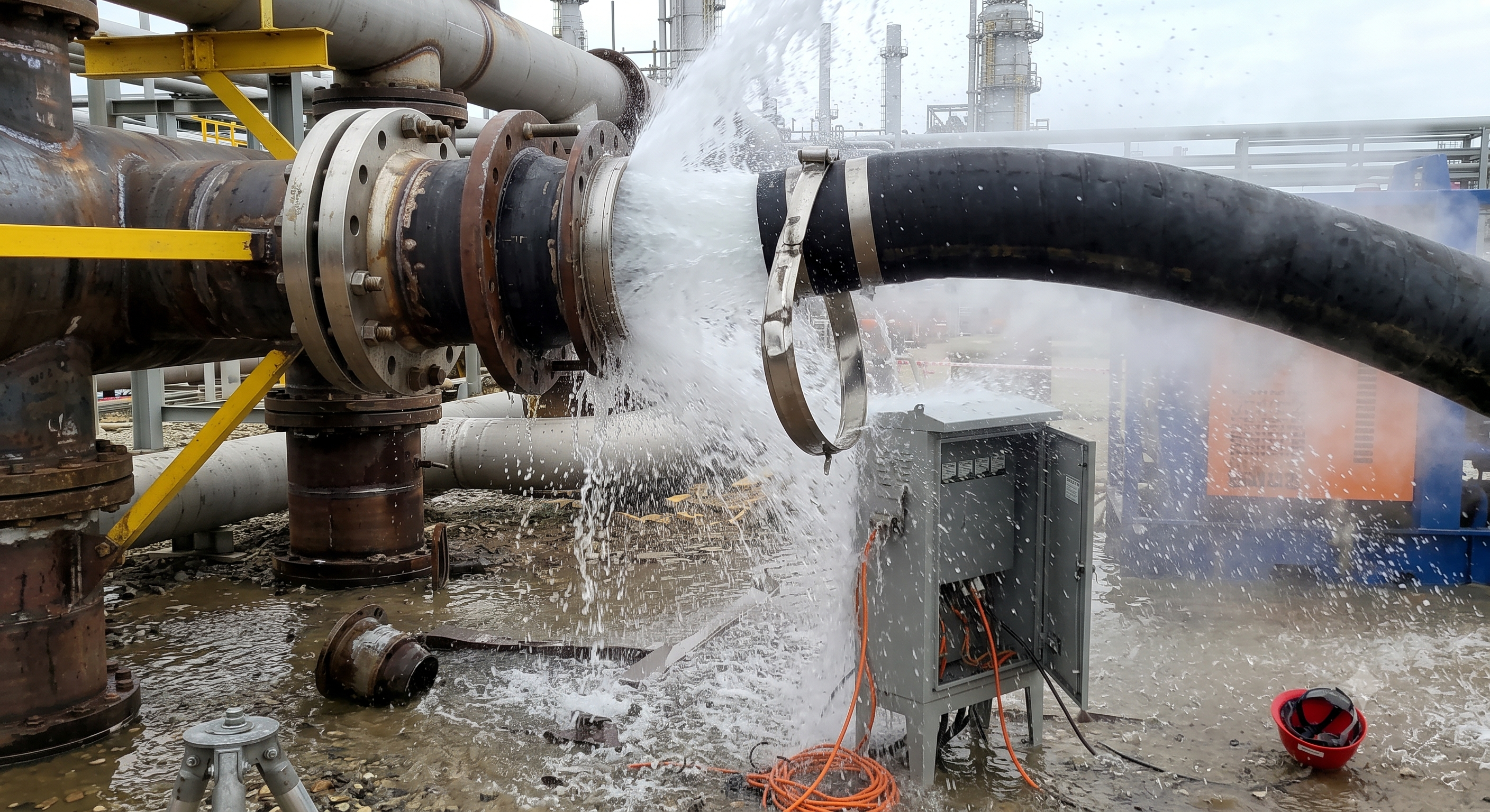
Retained AI-generated educational illustration; not an actual incident photograph.
The scenario and record comparisons are fictional teaching examples, not records of real incidents, measurements, inspections, signatures or approvals.
| Item | Fictional scenario |
|---|---|
| Initial situation | A crew connects a temporary water-fill hose to a long process line. |
| Changed condition | The drawing still shows a valve between the low-pressure fill connection and the test pump, but its isolation status is unconfirmed. |
| Failure path | A restricted high-point vent and a rapid valve movement could combine with pump head to overload a weak coupling. |
| Possible outcome | A released hose can strike personnel while the escaping water floods nearby electrical equipment. |
| Prevention barrier | Hold filling; establish the pressure boundary, vent path, rated assembly and remotely accessible stop arrangement before a fresh release. |
Failure mechanisms
The pressure envelope includes pump behaviour, static head from elevation and foreseeable transients. Check the lowest-rated complete assembly at its actual temperature and medium; the hose marking alone does not validate couplers, adaptors, gaskets or restraints. Prevent later test pressure from reaching an unsuitable fill line by the engineered separation/isolation arrangement.
Filled water mass loads the pipe and every temporary support. Check ground bearing, spans, anchor loads and anti-roll protection. An apparently stable empty line can settle during filling; a worker must not enter under it to adjust a loaded support.
Rapid velocity change can produce pressure waves. Trapped air adds compressible stored energy and complicates the response; venting does not prove that surge is eliminated. A simple Joukowsky estimate is not a complete design for branched lines, air pockets or pump trips. Vent capacity and closure sequence must suit the actual route and fill plan.
Coupler locking and hose restraint perform different functions. Select the restraint, anchor and installation slack from the actual manufacturer instructions; do not prescribe a taut generic cable. Restraint does not contain a jet or justify proximity. Use the pump-specific start and minimum-flow/overpressure provisions; a fixed discharge-valve percentage is not safe for every pump.
Decision sequence
| Decision stage | What to verify |
|---|---|
| Known facts | Match the current P&ID, fill connection and separate test boundary; resolve every unknown rating. |
| Unresolved matters | Verify lifting, full-water supports and compatible joints while depressurized. |
| Reason to hold | Check hose locks, restraint anchors, vent outlets, gauges, relief and remote observation positions. |
| Required evidence | Fill only under the approved pump/flow sequence; stop for leakage, movement, abnormal pressure or loss of contact. |
| Restart decision | Isolate all feeds, including gravity sources; safely relieve and verify each trapped section before disconnection. Confirm the test boundary separately before handover. |
5. Hold and proceed decisions
| Condition | Action | Evidence | Proceed when |
|---|---|---|---|
| Rating unknown | Do not start | Verify complete assembly | Ratings verified |
| Vent restricted | Stop filling | Review path and capacity | Vent path ready |
| Leak or movement | Stop remotely | Isolate and reassess | Fresh release |
| Test requested | Hold pressure rise | Separate fill line safely | Test boundary verified |
Similar situations, different decisions
The scenario and record comparisons are fictional teaching examples, not records of real incidents, measurements, inspections, signatures or approvals.
| Comparison | Situation A | Situation B |
|---|---|---|
| Pump stopped | Pressure or gravity feed remains | Verified isolation and local pressure release |
| Restraint fitted | Jet hazard and failed coupling remain | Compatible coupling, lock and rated restraint |
| One gauge reads zero | Another isolated pocket may retain pressure | Verify each relevant section by the planned method |
6. Roles and supervision
| Role | Responsibility |
|---|---|
| Work supervisor | Provide current drawings, pump and hose instructions, load data and the applicable test plan; coordinate the plant owner and other trades. Confirm the applicable Singapore workplace and pressure-system requirements; do not treat pneumatic-tool hose guidance as a legal rule for water filling. |
| Technical reviewer | Assign the filling controller and hold points; permit valve changes only through the agreed communication system. |
| Work crew | Assemble and inspect only while safely isolated; report damaged or untraceable components instead of adapting them on site. |
| Inspector / assessor | Observe pressure, vent discharge and supports from safe positions; stop on lost contact and keep people out of the hazard zone. |
| Release / handover authority | Review real records, defects and the transition to testing; sign only an assessment or inspection actually performed. |
Supervision, records, handover
| Job stage | Technical and procedural controls | Site verification |
|---|---|---|
| Scope and boundaries | 1. Approve fill/test separation2. Review weakest assembly3. Assign filling controller | 1. Boundary drawing2. Component register3. Pump duty data |
| Lifting coordination | 1. Review lift/exclusion plan2. Check gear records3. Assign signal operator | 1. Lift plan2. Gear inspection3. Chock positions |
| Support release | 1. Review full-water loading2. Check ground evidence3. Release protected crossings | 1. Load calculation2. Support locations3. Ground assessment |
| Hose acceptance | 1. Review assembly traceability2. Verify restraint instructions3. Record rejection of defects | 1. Assembly rating2. Lock engagement3. Restraint instructions |
| Filling permission | 1. Audit P&ID lineup2. Confirm vent/relief provision3. Release communication test | 1. Valve lineup2. Vent routing3. Gauge/relief data |
| Test handover | 1. Review isolation evidence2. Reconcile trapped sections3. Issue separate test release | 1. Isolation record2. Zero-pressure evidence3. Drain condition |
Singapore application
The filling supervisor controls the pump and communications. The temporary-works designer verifies the loaded arrangement and changes. The test authority independently accepts separation of unsuitable fill equipment before pressure increase, and the environmental coordinator accepts water handling.
7. Hold points and record quality
| Hold point | Evidence before release | Confirmation / approval |
|---|---|---|
| Start | Installation and controlled water filling of an identified industrial piping system using temporary rigid pipe and hose. Record the pump, route, medium, temperature, elevation, component ratings and intended test interface. Keep people outside the assessed jet, whip and falling-object zones. | |
| HP-1 Route and support | Load calculation · Support locations · Ground assessment · Access route | |
| HP-2 Connect hoses | Assembly rating · Lock engagement · Restraint instructions · Hose inspection | |
| HP-3 Line up and vent | Valve lineup · Vent routing · Gauge/relief data · Communication test | |
| HP-4 Stop and hand over | Isolation record · Zero-pressure evidence · Drain condition · Separate test release |
Complete after actual checks. Recheck after changes, defects or shift handover.
Record comparison examples
The scenario and record comparisons are fictional teaching examples, not records of real incidents, measurements, inspections, signatures or approvals.
The boxes are static record prompts, not interactive or saved approvals. A tick does not establish suitability or permission to restart. Record the evidence, person, time and unresolved issues; retain the change history.
| Record type | Insufficient record | Record checklist |
|---|---|---|
| Boundary | Only marked OK | □ Boundary drawing□ Component register□ Pump duty data□ Isolation plan |
| Supports | Only marked OK | □ Load calculation□ Support locations□ Ground assessment□ Access route |
| Hoses | Only marked OK | □ Assembly rating□ Lock engagement□ Restraint instructions□ Hose inspection |
| Handover | Only marked OK | □ Isolation record□ Zero-pressure evidence□ Drain condition□ Separate test release |
8. Pre-work checks and emergency response
| Check item | Result | Person / action |
|---|---|---|
| □ Define fill boundary: Boundary drawing | ||
| □ Offload and rig: Lift plan | ||
| □ Route and support: Load calculation | ||
| □ Assemble joints: Joint component IDs | ||
| □ Connect hoses: Assembly rating | ||
| □ Line up and vent: Valve lineup | ||
| □ Control filling: Fill limit basis | ||
| □ Stop and hand over: Isolation record | ||
| □ Release / handover authority |
Stop work
Stop for unverified ratings, a blocked vent, abnormal pressure or vibration, hose damage, leakage, support movement, rising water near electrics, entry into the exclusion zone or lost communication. Use the planned safe stop; do not close valves abruptly or assume stopping the pump removes pressure. Restart only after correction and a fresh release.
Emergency response
Raise the site alarm and keep people clear of the hose and water path. Operate remote isolation only as planned; have competent personnel control electrical exposure without entering flooded areas. Do not grab a moving hose, tighten a live joint or use a hand to find a leak. Suspected fluid injection requires urgent medical assessment even when the wound seems small.
9. Sources and review limits
Public-source review: 14 October 2026. Only the material and limits identified below were reviewed.
| Source | Reviewed material | Task application |
|---|---|---|
| MOM - Risk management | Responsibilities; routine and non-routine work; hierarchy of control and risk assessment team. Official explanation of WSH Risk Management duties, not a complete consolidated statutory text. | Assess temporary assemblies, changing support loads and foreseeable test backfeed. |
| WSHC - Planning a Lift | Main guidance on lifting plans, load, equipment, crew, method, communication, environment and changed conditions. Official guidance. The plan and permit requirements must be determined for the actual lifting operation; this page is not a universal permit rule. | Plan pipe unloading and rated gear before removing bundle restraint. |
| UK HSE - Pressure testing GS4 | Pages 1-8 text on stored energy, connectors, hoses, venting, remote monitoring, segregation and pressure release. Foreign technical guidance only. UK duties, enclosure thickness examples and test values are not adopted as Singapore requirements. This article covers filling, not the separate pressure test. | Use foreign technical lessons on connector integrity, venting and stored-energy segregation within this filling scope. |
| PUB - Written Approval for trade effluent | Main overview and application/change sections: public-sewer discharge approval, business/location scope and changed processes or chemicals. Decision-flow image not reviewed. Actual effluent classification, discharge quality and approval conditions require separate site verification; sewer approval is not open-drain permission. | Verify the public-sewer approval and conditions if the collected water is trade effluent; determine other disposal routes separately. |
Selected public official sources were reviewed on 14 October 2026 within the recorded scope. No full consolidated legal audit, paid Singapore Standard, actual model manual, site inspection, engineering calculation or professional approval is claimed. Verify current detailed requirements and actual equipment/site records before use.
AI-generated reference material. It has not been verified or approved by a professional. Before use, a qualified person must review and adapt it to applicable Singapore requirements, the actual equipment and site, and approved safe work procedures.
10. PDF use and frequently asked questions
PDF A covers basic task controls; B focuses on technical failures; C covers supervision, records and handover. The article has eight stages with four items per main cell; each PDF has six key stages with three items per main cell. P/S/R/A, measurements, confirmations and signatures remain blank for actual site assessment.
Content group ID
jsa-hydro-testing
Does a whip restraint make a coupling safe?
No. It supplements a compatible rated connection and its specified lock; it does not seal a leak or contain the fluid jet.
Is a low-pressure filling pump harmless?
No. Assess shutoff behaviour, elevation and transients, plus the possibility of later test pressure backfeeding the fill connection.
May every pump start with the discharge valve partly closed?
No. Follow its specific start procedure, minimum-flow and overpressure provisions. A universal percentage can create a deadhead hazard.
Does a zero reading allow the hose to be disconnected?
Only after the planned isolation, safe pressure release and verification cover every relevant trapped section; check gauge suitability and condition. Never loosen a joint to test for pressure.
Has a professional verified or approved this document?
No. Public sources and editorial, layout and consistency checks were reviewed using AI. No site inspection or professional technical approval has been performed. Obtain appropriate professional review before use.
Singapore application
Retain water in the test object where its separate plan requires it. Drain only the identified isolated sections using the planned air-admission and collection method; do not inadvertently empty the test object while disconnecting a fill branch. Read A, B and C together with all eight JSA stages and the approved work procedure. The sheets are complementary extracts, not separate work authorisations.
11. Authorship and revision history
AI-generated reference material. It has not been verified or approved by a professional. Before use, a qualified person must review and adapt it to applicable Singapore requirements, the actual equipment and site, and approved safe work procedures.
| Date / edition | Authorship and scope | Professional approval |
|---|---|---|
| 2026-07-20 / Korean source | Original topic and educational illustration retained as references. Source content is unchanged. | Not asserted |
| 14 October 2026 / Singapore 1.0 | Added Singapore lifting coordination and PUB discharge interface while preserving filling-only scope and separate pressure-test acceptance. | Not performed |
Source topic: https://smartjsabridge.com/ko/case-study/jsa-hydro-testing