Determine the governing province, territory or federal regime first. Ontario O. Reg. 213/91 sections 87–92 cover formwork and related support systems, including specific design and inspection provisions for systems within section 89. They are not nationwide rules. Alberta has its own OHS Code, including section 352 for temporary supporting structures. This revised JSA follows retaining wall formwork from delivery to controlled removal. The central decisions are whether each erection stage is stable, whether the assembled system can resist the planned concrete pressure, and whether the wall and retained supports permit stripping. Existing lifting, bracing, access, monitoring and housekeeping controls are retained with their limits made explicit.
Stable erection, controlled pouring and evidence-based stripping
This is reference content written and revised with AI. It has not been verified or approved by a professional. Review by a suitably qualified professional and site authorisation are required before use.
Stop work
Stop for missing supports or locking parts, anchor movement, unusual leakage or bulging, unexpected ground movement, unsafe wind, loss of communication, access defects or an unreviewed mix/rate change. Keep workers clear of the possible failure path. A low risk score or an unsigned checklist cannot override a failed hold point.
1. Legal and technical scope
| Basis | Application limits |
|---|---|
| Ontario O. Reg. 213/91 | Official indexed consolidation and provisions 87–92 reviewed; direct base-page retrieval unavailable. |
| Alberta OHS Code — Part 23 | Read section 352 on temporary supporting structures and certification; not a design check. |
| Alberta OHS legislation | Official entry point for jurisdiction-specific current legislation. |
Determine the governing province, territory or federal regime first. Ontario O. Reg. 213/91 sections 87–92 cover formwork and related support systems, including specific design and inspection provisions for systems within section 89. They are not nationwide rules. Alberta has its own OHS Code, including section 352 for temporary supporting structures.
The original Edmonton example is retained only as a hypothetical Alberta setting. Alberta section 352 references a specified CSA edition and defines circumstances requiring professional-engineer certification; Ontario requirements must not be substituted for it. Check the site system against the current applicable text and provincial engineering requirements. The Ontario search extract indicated consolidation from 20 April 2026; direct base-page retrieval did not return readable text during this review.
2. Scope and required inputs
Included scope
Wall panels, push-pull props, anchors, ties, walers, working platforms and planned lifting interfaces. Identify whether the system has opposing tied faces or is a one-sided form relying on a designed reaction frame and foundation. Review each temporary stage before people or loads are introduced.
Separate review
This reference does not design temporary works or authorise a lift, pour, stripping operation or backfilling. Excavation support, lifting engineering, permanent wall design, confined-space work and any fall rescue need their own applicable plans and competent review. A release to strip is not a release to place soil behind the wall.
| Required input | What to verify |
|---|---|
| Design and ground | Current design reference · Ground acceptance record · System and mix details · Limits and stop criteria |
| Receive and store | Panel weight and lift plan · Accessory inspection record · Storage layout and limits · Briefing and signaller |
| Erect and brace | Brace and anchor checks · Release-to-unhook record · Platform inspection record · Actual weather assessment |
| Pre-pour inspection | Signed assembly inspection · Component identity record · Deviation closeout record · Pour release and limits |
| Release for stripping | Strength basis and lot · Designer removal criteria · Support retention plan · Authorised release record |
| Clear and hand over | Housekeeping check · Defect quarantine log · Stack and access check · Wall handover restrictions |
No universal brace angle, tie spacing, stacking height, wind speed, concrete placement rate or stripping age is assigned. Enter values from the actual design, product instructions, concrete specification and governing rules, with units and document revisions. Paid standards, project calculations, product manuals and test results have not been independently reviewed for this site. Conflicting requirements require technical resolution before work.
Select head, eye, hand and foot protection for actual handling and cement exposure. Prevent wet concrete contact and provide washing arrangements. Prefer protected working platforms and edge protection; where personal fall protection remains necessary, verify the anchor, clearance, compatibility and rescue arrangements. Respiratory and hearing protection follow exposure assessment and do not replace dust or noise control.
3. Eight-stage JSA
| Job stage | Hazards and effects | Failure factors | Technical and procedural controls | Site verification | P | S | R | A |
|---|---|---|---|---|---|---|---|---|
| 1. Design and ground | 1. Unstable support ground2. Unresolved wind load3. Wrong pressure model4. Nearby excavation failure | 1. Missing design revision2. Unchecked anchor substrate3. Wrong form configuration4. Unplanned plant surcharge | 1. Confirm staged load paths2. Assess foundation capacity3. Identify one-sided systems4. Review excavation interface | 1. Current design reference2. Ground acceptance record3. System and mix details4. Limits and stop criteria | ||||
| 2. Receive and store | 1. Suspended panel strike2. Stack overturning3. Rigging or clamp failure4. Manual handling strain | 1. Wrong lifting attachment2. Damaged stacking bearers3. People under load4. Unknown panel weight | 1. Use specified lift points2. Set stable storage supports3. Separate lifting area4. Plan mechanical handling | 1. Panel weight and lift plan2. Accessory inspection record3. Storage layout and limits4. Briefing and signaller | ||||
| 3. Erect and brace | 1. Unbraced panel collapse2. Wind-driven panel swing3. Fall from access platform4. Crushing during alignment | 1. Early sling release2. Unverified brace anchorage3. Unprotected platform edge4. Hands in closing joints | 1. Follow erection sequence2. Secure designed restraints3. Provide protected access4. Keep clear of pinch points | 1. Brace and anchor checks2. Release-to-unhook record3. Platform inspection record4. Actual weather assessment | ||||
| 4. Pre-pour inspection | 1. Tie or waler failure2. Anchor or base movement3. Fall through access gaps4. One-sided frame overload | 1. Missing locking hardware2. Wrong tie spacing or type3. Unapproved site alteration4. Open stop-end unsupported | 1. Match approved assembly2. Check tie and waler system3. Close design deviations4. Inspect access and stop-ends | 1. Signed assembly inspection2. Component identity record3. Deviation closeout record4. Pour release and limits | ||||
| 5. Place and monitor | 1. Excess concrete pressure2. Form bulging or leakage3. Pump hose movement4. Cement splash and burns | 1. Rate or mix changed2. Warning signs ignored3. Unsafe repair during pour4. Observer cannot stop pump | 1. Follow approved pour plan2. Watch from protected place3. Stop and withdraw on fault4. Control hose and exposure | 1. Pour and mix log2. Observation and stop record3. Communication check4. Weather and movement log | ||||
| 6. Release for stripping | 1. Immature concrete failure2. Loss of wall stability3. Premature support removal4. Unexpected imposed load | 1. Time alone used as proof2. Wrong test lot referenced3. Backfill release assumed4. No agreed removal sequence | 1. Check strength evidence2. Review actual load state3. Retain necessary supports4. Obtain stripping release | 1. Strength basis and lot2. Designer removal criteria3. Support retention plan4. Authorised release record | ||||
| 7. Strip and lower | 1. Sudden panel detachment2. Falling panel or hardware3. Fall at changing edge4. Adjacent panel instability | 1. Unsupported panel release2. Uncontrolled prying force3. Premature guardrail removal4. Brace sequence ignored | 1. Restrain before release2. Lower by planned method3. Maintain edge protection4. Keep exclusion zone clear | 1. Panel restraint check2. Removal sequence briefing3. Rigging and zone checks4. Remaining stability check | ||||
| 8. Clear and hand over | 1. Nails and projecting ties2. Unstable recovered stack3. Excavation edge overload4. Early backfill loading | 1. Sharp debris left exposed2. Damaged panel reused3. Stack outside layout4. Wall restrictions omitted | 1. Collect and protect sharps2. Quarantine damaged parts3. Store within agreed limits4. Transfer loading restrictions | 1. Housekeeping check2. Defect quarantine log3. Stack and access check4. Wall handover restrictions |
PDF A covers basic task controls; B focuses on technical failures; C covers supervision, records and handover. The article has eight stages with four items per main cell; each PDF has six key stages with three items per main cell. P/S/R/A, measurements, confirmations and signatures remain blank for actual site assessment.
4. Fictional scenario and failure mechanisms
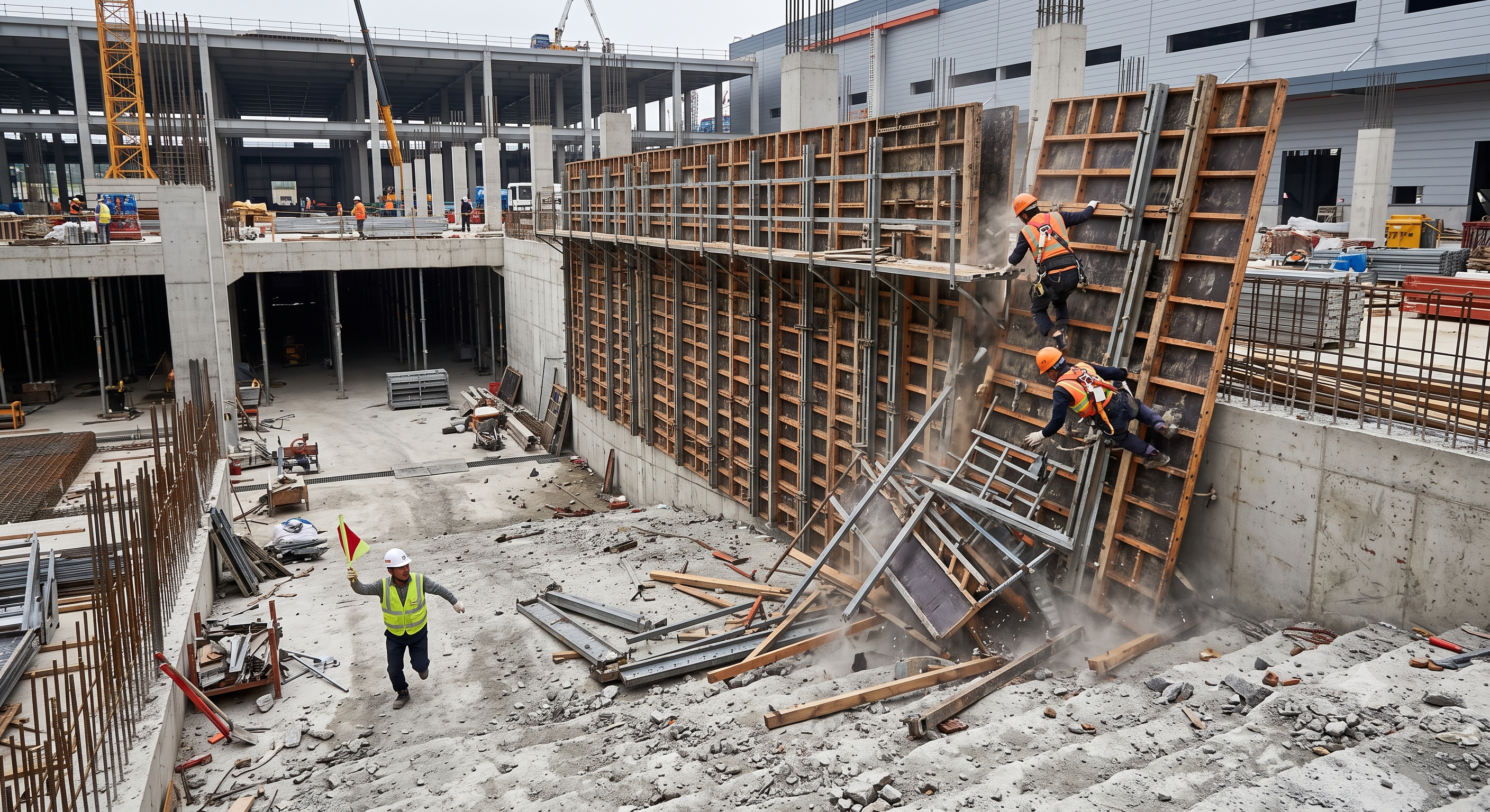
Retained educational illustration; not evidence of an actual incident.
The scenario and record comparisons are fictional teaching examples, not records of real incidents, measurements, inspections, signatures or approvals.
| Item | Fictional scenario |
|---|---|
| Initial situation | In a hypothetical Edmonton, Alberta, project a crew erects large wall panels near an excavation as the weather changes. No actual incident, injury or OHS stop-work order is asserted. |
| Changed condition | Pressure to release the crane leads to a proposed unhooking before brace anchorage and the temporary stage have been checked. The neighbouring panel joint is incorrectly treated as proof of overall stability. |
| Failure path | A wind gust or eccentric platform load could rotate or slide the unsupported assembly. People on the platform and within the potential fall area would be exposed; the precise outcome cannot be inferred from the illustration. |
| Possible outcome | Keep the crane operation under its lift plan, stop the proposed release, clear the potential collapse area and obtain a safe stabilisation method from the responsible specialists. Do not send people under an unstable panel to fit a missing brace. |
| Prevention barrier | Resume only after the required supports and anchors are installed and checked, actual conditions match the design, and the responsible person releases that erection stage. Record the changed sequence and brief the crew. |
Failure mechanisms
Before pouring, wind, lifting movement and eccentric platform loads act through the temporary assembly and its supports. Adjacent panels or ground friction alone do not demonstrate adequate stability. Anchor capacity depends on the actual substrate, installation and design actions; an arbitrary angle or generic expansion anchor is not a substitute for design.
During pouring, pressure depends on concrete properties, temperature, placement rate, vibration and the design model. It may approach liquid-head pressure in relevant conditions. There is no general rule that pressure rises exponentially. Ties, walers, connections and supports form a connected load path, so a local defect can affect adjoining elements.
A one-sided system may have no through-ties to an opposing face. Its reaction frames, anchorage and foundation must carry the design actions. Do not transfer tie spacing or push-pull prop details from a two-sided system into a one-sided arrangement without technical review.
Stripping changes the support and access arrangements as well as exposing the concrete. The authorised strength basis must match the actual wall and loading stage. Remaining restraints, future wind, soil, plant and construction loads still matter after removal; concrete appearance or elapsed time alone does not establish release.
Decision sequence
| Decision stage | What to verify |
|---|---|
| Known facts | Identify the wall, system, current drawing and temporary stage. |
| Unresolved matters | Find the missing brace, change, abnormal movement or unverified evidence. |
| Reason to hold | Stop the affected operation and isolate its danger area. |
| Required evidence | Have the authorised specialists resolve the cause, inspect the corrected system and document the applicable release. |
| Restart decision | Communicate the new limits and verify conditions before the next stage. |
5. Conditional decisions and common errors
| Condition | Action | Evidence | Proceed when |
|---|---|---|---|
| Brace missing or anchor uncertain | Stop erection release; keep people clear and obtain a designed stabilisation method. | Brace layout, anchor installation evidence and stage inspection record. | Specified restraints installed and checked. |
| Pour conditions differ or form moves | Stop concrete placement, warn the crew and withdraw from the potential failure zone. | Actual mix/rate log, movement observations and technical change review. | Cause resolved; system re-inspected and pour reauthorised. |
| Stripping evidence incomplete | Retain supports and hold stripping until wall-specific evidence and sequence are reviewed. | Strength basis, wall/lot identity, actual loads and written release scope. | Removal criteria met and stripping release issued. |
| Weather or access becomes unsafe | Suspend affected lifting or elevated work and reassess protection and conditions. | Weather assessment, applicable limits and access/rescue inspection. | Conditions within limits and protected access restored. |
Similar situations, different decisions
The scenario and record comparisons are fictional teaching examples, not records of real incidents, measurements, inspections, signatures or approvals.
| Comparison | Situation A | Situation B |
|---|---|---|
| Erection | “The next panel is connected, so unhook.” | Check the designed temporary support state and record the release. |
| Pouring | “The usual pump speed is acceptable.” | Compare the actual mix and placement with the approved pressure assumptions. |
| Stripping | “The wall looks hard and the next crew is waiting.” | Match the strength evidence, loads and retained supports to the stripping release. |
6. Roles and responsibilities
| Role | Responsibility |
|---|---|
| Work management | Coordinate contractors, access, deliveries, excavation interfaces and stop authority. Ensure competent people have current drawings and sufficient time to carry out checks. |
| Design review | The responsible temporary-works and permanent-works specialists define stage loads, stability, acceptance criteria and interfaces. The required professional status and checking arrangements depend on jurisdiction and project. |
| Lifting and assembly | The designated lifting and assembly personnel follow the approved sequence, verify product compatibility and obtain release before unhooking. Qualifications must match actual equipment and duties. |
| Pour supervisor and observer | Confirm the pour release and agreed limits; keep a usable stop link to the pump. Observe from a protected position and stop on unexplained movement or changed conditions. |
| Stripping and handover | The authorised reviewer checks the concrete evidence and removal scope. The supervisor maintains support, exclusion and fall protection through removal and transfers wall loading restrictions. |
Supervision, records, handover
| Job stage | Technical and procedural controls | Site verification |
|---|---|---|
| Design authority | 1. Appoint design reviewer2. Control issued drawings3. Resolve one-sided reactions | 1. Design responsibility record2. Issued drawing register3. Assumption review record |
| Competence and roles | 1. Verify assigned competence2. Brief agreed signals3. Name stop and release roles | 1. Competence evidence2. Crew briefing record3. Authority allocation |
| Inspection system | 1. Arrange staged inspections2. Trace critical components3. Close defects before release | 1. Stage inspection records2. Anchor and tie traceability3. Defect closure evidence |
| Pour change control | 1. Recheck changed conditions2. Record pour progression3. Test stop communication | 1. Mix change review2. Pour monitoring record3. Stop-system check |
| Strip authorisation | 1. Match evidence to wall lot2. State retained supports3. Separate backfill release | 1. Strength evidence reference2. Written stripping scope3. Loading restriction record |
| Emergency and handover | 1. Plan rescue from safe area2. Keep failed zone isolated3. Brief receiving supervisor | 1. Emergency readiness check2. Recovery authority record3. Signed restriction handover |
7. Hold points and record comparison
| Hold point | Evidence before release | Confirmation / approval |
|---|---|---|
| Start | Wall panels, push-pull props, anchors, ties, walers, working platforms and planned lifting interfaces. Identify whether the system has opposing tied faces or is a one-sided form relying on a designed reaction frame and foundation. Review each temporary stage before people or loads are introduced. | |
| HP-1 Erect and brace | Brace and anchor checks · Release-to-unhook record · Platform inspection record · Actual weather assessment | |
| HP-2 Pre-pour inspection | Signed assembly inspection · Component identity record · Deviation closeout record · Pour release and limits | |
| HP-3 Release for stripping | Strength basis and lot · Designer removal criteria · Support retention plan · Authorised release record | |
| HP-4 Strip and lower | Panel restraint check · Removal sequence briefing · Rigging and zone checks · Remaining stability check |
Complete after actual checks. Recheck after changes, defects or shift handover.
Record comparison examples
The scenario and record comparisons are fictional teaching examples, not records of real incidents, measurements, inspections, signatures or approvals.
The boxes are static record prompts, not interactive or saved approvals. A tick does not establish suitability or permission to restart. Record the evidence, person, time and unresolved issues; retain the change history.
| Record type | Insufficient record | Record checklist |
|---|---|---|
| Design and ground | Only “OK” | □ Current design reference□ Ground acceptance record□ System and mix details□ Limits and stop criteria |
| Erect and brace | Only “OK” | □ Brace and anchor checks□ Release-to-unhook record□ Platform inspection record□ Actual weather assessment |
| Place and monitor | Only “OK” | □ Pour and mix log□ Observation and stop record□ Communication check□ Weather and movement log |
| Release for stripping | Only “OK” | □ Strength basis and lot□ Designer removal criteria□ Support retention plan□ Authorised release record |
8. Site checklist and emergency response
| Check item | Result | Person / action |
|---|---|---|
| □ Design and ground: Current design reference | ||
| □ Receive and store: Panel weight and lift plan | ||
| □ Erect and brace: Brace and anchor checks | ||
| □ Pre-pour inspection: Signed assembly inspection | ||
| □ Place and monitor: Pour and mix log | ||
| □ Release for stripping: Strength basis and lot | ||
| □ Strip and lower: Panel restraint check | ||
| □ Clear and hand over: Housekeeping check | ||
| □ Release / handover authority |
Stop work
Stop for missing supports or locking parts, anchor movement, unusual leakage or bulging, unexpected ground movement, unsafe wind, loss of communication, access defects or an unreviewed mix/rate change. Keep workers clear of the possible failure path. A low risk score or an unsigned checklist cannot override a failed hold point.
Emergency response
Raise the alarm, stop affected equipment safely and prevent entry into the collapse or suspended-load area. Activate the site emergency plan and trained rescue arrangements; avoid impulsive entry beneath unstable components. Stabilisation and recovery require a separately reviewed method. Preserve observations and report through the applicable incident process.
9. Sources and review limits
2026-10-12
| Source | Scope and limitations |
|---|---|
| Ontario O. Reg. 213/91 | Official indexed consolidation and provisions 87–92 reviewed; direct base-page retrieval unavailable. |
| Alberta OHS Code — Part 23 | Read section 352 on temporary supporting structures and certification; not a design check. |
| Alberta OHS legislation | Official entry point for jurisdiction-specific current legislation. |
This is reference content written and revised with AI. It has not been verified or approved by a professional. Review by a suitably qualified professional and site authorisation are required before use.
10. PDF guidance and FAQ
PDF A covers basic task controls; B focuses on technical failures; C covers supervision, records and handover. The article has eight stages with four items per main cell; each PDF has six key stages with three items per main cell. P/S/R/A, measurements, confirmations and signatures remain blank for actual site assessment.
Content group ID
jsa-wall-form
Can the JSA set a universal pour rate?
No. Use the applicable design and actual concrete conditions; reassess changes before resuming.
Can the crane be released after joining adjacent panels?
Only when the planned temporary support state has been achieved, checked and released under the lifting and erection arrangements. A joint alone proves neither anchorage nor stability.
Does stripping permit immediate backfilling?
No. Backfill and other loading need a separate check of the permanent wall, concrete strength, restraints and design sequence.
What can be entered into Smart JSA Bridge?
Enter the wall identity, system, design revisions, limits, responsible roles, inspection evidence and stage decisions. These are proposed documentation inputs; this article does not establish that the software calculates structural designs or guarantees compliance.
Has a professional verified or approved this document?
No. Public sources and editorial, layout and consistency checks were reviewed using AI. No site inspection or professional technical approval has been performed. Obtain appropriate professional review before use.
11. Revision history and authorship
This is reference content written and revised with AI. It has not been verified or approved by a professional. Review by a suitably qualified professional and site authorisation are required before use.
| Date | Version | Change | Review status |
|---|---|---|---|
| 2026-09-13 | Original version unmarked | Original preserved | No professional approval |
| 2026-10-12 | 1.1 | Decisions, records, JSA and PDFs revised | No professional approval |
The revision retains delivery, stable stacking, bracing before crane release, tie/waler checks, protected access, monitoring, controlled lowering and housekeeping. It removes preset risk scores and unsupported incident/investigation claims; the case is explicitly hypothetical. Universal tie-off, setbacks, brace angles and placement rates are replaced with applicable design and site requirements. Pressure is no longer described as exponentially rising, and stripping is distinguished from backfill release. Unverified software calculation and compliance claims are removed. Permanent or structurally required ties must not be cut merely to complete housekeeping. Removed generic 1.5 m/h, L/360, 45–60 degree and fixed stack/setback values, the unverified pressure formula and nationwide engineering assertions. CSA and ASME references are not treated as universal Canadian legal mandates.