A hard-looking sprayed surface does not establish that the heading can accept people, drilling or the next excavation round. Ground conditions, the installed support, concrete development and the next load must be assessed together. Keep spraying, steel erection, drilling and cleanup separated until their respective release conditions are met.
Release the next activity from evidence, not surface appearance
This is reference content written and revised with AI. It has not been verified or approved by a professional. Review by a suitably qualified professional and site authorisation are required before use.
Stop work
Stop for loose ground, support cracking or movement, missing release evidence, suspected misfire, ventilation or communication loss, uncontrolled hose movement or water inflow beyond the plan. Withdraw by the protected route and retain the exclusion.
1. Legal and technical scope
| Basis | Application limits |
|---|---|
| WorkSafeBC — OHS Regulation Part 22 | Reviewed scope and ground-support/shotcrete provisions, especially 22.62–22.64: protected work, source dust control, downwind restrictions, suitable PPE and immediate stop communication. |
Canadian requirements depend on the jurisdiction and type of operation. British Columbia Part 22 is used as an expressly provincial example for underground work; it is not a Canada-wide or mining rule.
The Ontario full text could not be retrieved in this review. Original Ontario and CSA claims therefore do not establish national compliance, a four-hour waiting rule or a universal early-strength threshold. Verify the actual jurisdiction before use.
2. Scope and required inputs
Included scope
Review the civil tunnel heading, scale loose ground from protection, prepare pumping and ventilation, apply designed sprayed concrete, erect ribs and mesh, release bolt drilling, inspect completed support and hand over restrictions. The actual support design determines the order; the eight stages are planning prompts, not a mandatory construction sequence.
Separate review
Blasting and misfire treatment, mining operations, compressed-air work, major water inflow, structural support design and entry into hazardous atmospheres require separate competent planning. Washing a face does not establish that unexploded charges are absent. Do not touch, probe or drill suspected remnants; isolate and refer them to the authorised blasting specialist.
| Required input | What to verify |
|---|---|
| Review heading | Face inspection record · Support plan revision · Air and blast clearance · Water and escape check |
| Scale and protect | Scaling inspection · Protected work position · Exclusion boundary · Signal and stop test |
| Set pump and air | Line and joint inspection · Pressure and restraint plan · Ventilation measurements · Mix and chemical data |
| Spray first layer | Mix and dose record · Layer thickness checks · Air and dust controls · Boom and rebound zone |
| Release and bolt | Early strength evidence · Bolt installation record · Blast release and marking · Drill and grout checks |
| Isolate and hand over | Isolation and pressure check · Washout handling record · Final support status · Open issues and owner |
No paid ACI, BS, CSA, AS/NZS or EN standard or model-specific pump manual was read. Obtain the actual design, test procedure, chemical safety data and equipment instructions. A universal 1 MPa, 1.5 MPa, 200 psi or two-hour waiting rule is not established by this review. Mix, temperature, thickness, ground and the next activity determine the release criteria; 200 psi is about 1.38 MPa, not 1.5 MPa.
Control dust at source and design tunnel ventilation for the actual contaminants, oxygen demand, diesel plant and work sequence. Verify performance and personal exposure; an airflow reading alone does not establish silica compliance. Select suitable respiratory protection, fit-test tight-fitting types, and address eye/face splash, cement burns, noise and sharp mesh. PPE does not permit entry below unstable ground.
3. Eight-stage JSA
| Job stage | Hazards and effects | Failure factors | Technical and procedural controls | Site verification | P | S | R | A |
|---|---|---|---|---|---|---|---|---|
| 1. Review heading | 1. Rockfall at face2. Gas or oxygen hazard3. Water inflow4. Unfound misfire | 1. Changed ground ignored2. Old support drawing3. Re-entry not cleared4. No escape route | 1. Map current ground2. Apply support sequence3. Obtain re-entry release4. Plan protected escape | 1. Face inspection record2. Support plan revision3. Air and blast clearance4. Water and escape check | ||||
| 2. Scale and protect | 1. Falling loose blocks2. Plant strikes worker3. Cab penetration4. Dust exposure | 1. Worker under loose rock2. Unprotected machine3. Shared work zone4. Blind communication | 1. Scale from protected place2. Exclude unprotected entry3. Use suitable cab protection4. Maintain stop signal | 1. Scaling inspection2. Protected work position3. Exclusion boundary4. Signal and stop test | ||||
| 3. Set pump and air | 1. Hose whip or burst2. Chemical splash3. Electric shock4. Harmful atmosphere | 1. Worn or wrong coupling2. Blocked or kinked line3. Unsuitable electrical feed4. Poor ventilation | 1. Match rated components2. Secure and inspect joints3. Protect power supply4. Verify airflow and exposure | 1. Line and joint inspection2. Pressure and restraint plan3. Ventilation measurements4. Mix and chemical data | ||||
| 4. Spray first layer | 1. Rebound eye injury2. Silica inhalation3. Fresh concrete falls4. Boom crush injury | 1. Person in rebound path2. Wrong mix or dose3. Weak surface bond4. Lost pump communication | 1. Separate spraying zone2. Use designed wet mix3. Prepare surface and drains4. Maintain pump stop contact | 1. Mix and dose record2. Layer thickness checks3. Air and dust controls4. Boom and rebound zone | ||||
| 5. Fit ribs and mesh | 1. Dropped support rib2. Pinched hand or foot3. Sharp mesh injury4. Unstable steel set | 1. Rigging unsuitable2. Hands between joints3. Temporary bracing absent4. Unsupported work position | 1. Follow lift and brace plan2. Use alignment tools3. Protect sharp edges4. Work from protected zone | 1. Rigging and load check2. Base and bracing check3. Mesh fixing inspection4. Protected access check | ||||
| 6. Release and bolt | 1. Ground or lining fall2. Drill boom entrapment3. Misfire initiation4. Grout hose release | 1. Early strength assumed2. Wrong bolt or pattern3. Blast status unresolved4. Person near moving drill | 1. Verify design release2. Use specified bolt system3. Refer misfires to specialist4. Exclude drill movement zone | 1. Early strength evidence2. Bolt installation record3. Blast release and marking4. Drill and grout checks | ||||
| 7. Finish and inspect | 1. Falling fresh lining2. Hidden void or weak patch3. Dust during cleanup4. Loader collision | 1. Thickness not checked2. Rebound reused unchecked3. Support defect ignored4. Shared pedestrian route | 1. Inspect specified coverage2. Remove rebound safely3. Record and repair defects4. Separate cleanup traffic | 1. Thickness and test record2. Support defect closure3. Rebound disposal route4. Traffic and air check | ||||
| 8. Isolate and hand over | 1. Stored pressure release2. Alkaline water burn3. Unexpected pump start4. Unrecorded unsafe heading | 1. Coupling opened under load2. Energy not isolated3. Washwater uncontrolled4. Shift change without record | 1. Isolate and verify zero energy2. Use maker blockage procedure3. Contain washwater4. Transfer support restrictions | 1. Isolation and pressure check2. Washout handling record3. Final support status4. Open issues and owner |
PDF A covers basic task controls; B focuses on technical failures; C covers supervision, records and handover. The article has eight stages with four items per main cell; each PDF has six key stages with three items per main cell. P/S/R/A, measurements, confirmations and signatures remain blank for actual site assessment.
4. Fictional scenario and failure mechanisms
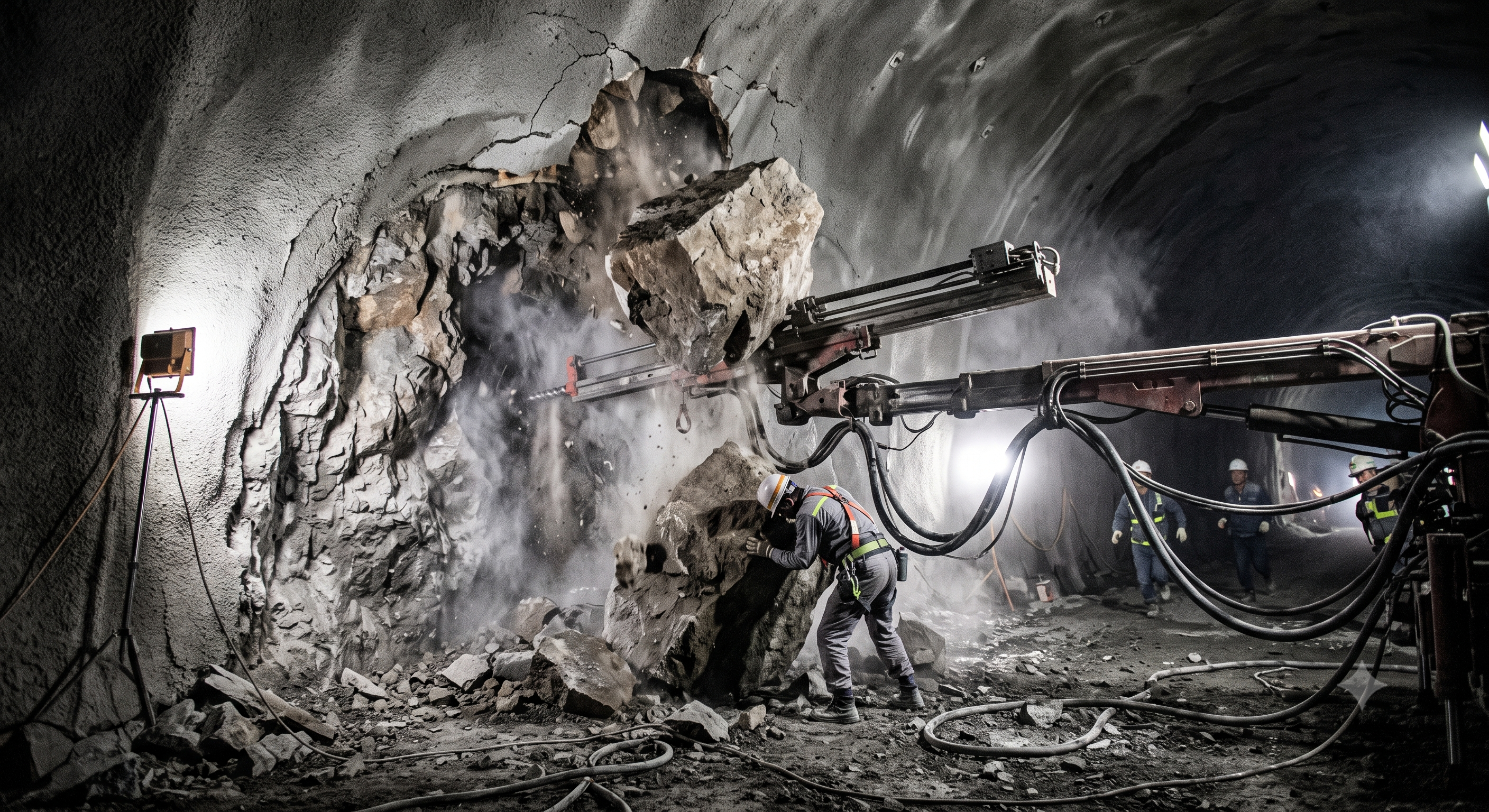
Retained educational illustration; not evidence of an actual incident.
The scenario and record comparisons are fictional teaching examples, not records of real incidents, measurements, inspections, signatures or approvals.
| Item | Fictional scenario |
|---|---|
| Initial situation | In this hypothetical heading, a first shotcrete layer has been placed and a drill waits behind the support boundary. |
| Changed condition | The supervisor proposes starting bolt drilling because the surface feels hard, but a batch change and cooler ground have not been assessed. |
| Failure path | Actual early strength, bond condition, thickness and the approved next load remain unverified; drilling or personnel access may disturb incomplete support. |
| Possible outcome | A worker entering below the exposed crown could be struck if ground or fresh lining detaches. No measured strength, injury or investigation is asserted. |
| Prevention barrier | Hold entry and drilling. Obtain the specified tests and ground inspection, resolve defects and record the competent release for that area and activity. |
Failure mechanisms
Excavation redistributes stress and exposes joints; block geometry, water and the remaining support affect stability. Loss of confinement does not make all friction zero, and rock classifications alone cannot predict a safe stand-up time for a particular heading.
Early compressive strength is one input to a designed release. Adhesion, coverage, thickness and ground behaviour also matter. A clock time or accelerator setting does not measure those properties, and drill vibration does not cause an identical immediate collapse in every ground condition.
A blocked delivery line can retain energy even after the pump stops. Use the manufacturer isolation, depressurisation and blockage procedure, prevent unexpected restart and verify the relevant sections are safe before opening. A generic cable restraint does not make incompatible or worn couplings acceptable.
Decision sequence
| Decision stage | What to verify |
|---|---|
| Known facts | In this hypothetical heading, a first shotcrete layer has been placed and a drill waits behind the support boundary. |
| Unresolved matters | The supervisor proposes starting bolt drilling because the surface feels hard, but a batch change and cooler ground have not been assessed. |
| Reason to hold | Actual early strength, bond condition, thickness and the approved next load remain unverified; drilling or personnel access may disturb incomplete support. |
| Required evidence | Stop for loose ground, support cracking or movement, missing release evidence, suspected misfire, ventilation or communication loss, uncontrolled hose movement or water inflow beyond the plan. Withdraw by the protected route and retain the exclusion. |
| Restart decision | Hold entry and drilling. Obtain the specified tests and ground inspection, resolve defects and record the competent release for that area and activity. |
5. Conditional decisions and common errors
| Condition | Action | Evidence | Proceed when |
|---|---|---|---|
| Ground differs | Stop entry; reassess support | Face log, support review and entry-release record | Support reviewed; entry authorised |
| Strength unverified | Hold entry and drilling | Specified strength-test results and work-release record | Strength criterion met; work released |
| Air control fails | Stop exposure and withdraw | Ventilation check and exposure-assessment record | Exposure controls verified |
| Blocked line | Isolate; use maker procedure | Isolation and residual-pressure check record | Isolation and zero pressure verified |
Similar situations, different decisions
The scenario and record comparisons are fictional teaching examples, not records of real incidents, measurements, inspections, signatures or approvals.
| Comparison | Situation A | Situation B |
|---|---|---|
| Hard surface | Visual set only: keep the drilling hold. | Required tests and complete support checked: authorised release may follow. |
| Stopped pump | Energy may remain behind a plug; no opening. | Isolation and safe depressurisation verified under the maker procedure. |
| Fan running | Duct leakage or recirculation may still expose workers. | Air distribution and exposure assessed against applicable criteria. |
6. Roles and responsibilities
| Role | Responsibility |
|---|---|
| Work management | Provide design, competent people, rescue resources and coordination of contractors. |
| Technical/design review | Specify support, inspection and release criteria; assess changes and unresolved defects. |
| Site supervision | Control exclusions and the actual sequence; record hold-point decisions and handover. |
| Operating crew | Inspect equipment, maintain pump/nozzle communication and stop on loss of control. |
| Air, traffic and rescue | Manage air and exposure assessment, traffic separation and the planned emergency response. |
Supervision, records, handover
| Job stage | Technical and procedural controls | Site verification |
|---|---|---|
| Plan control | 1. Review actual ground2. Confirm design revision3. Assign release authority | 1. Face inspection record2. Support plan revision3. Signal and stop test |
| Resources | 1. Verify crew competence2. Match plant to task3. Audit inspection evidence | 1. Scaling inspection2. Pressure and restraint plan3. Mix and chemical data |
| Interfaces | 1. Separate trades and zones2. Assign exclusion control3. Protect emergency access | 1. Mix and dose record2. Base and bracing check3. Traffic and air check |
| Release evidence | 1. Retain unproved holds2. Review tests and defects3. Record area-specific release | 1. Early strength evidence2. Bolt installation record3. Support defect closure |
| Event response | 1. Activate planned response2. Isolate affected work3. Require restart assessment | 1. Water and escape check2. Line and joint inspection3. Isolation and pressure check |
| Shift handover | 1. Record support status2. Carry forward restrictions3. Brief the next shift | 1. Rebound disposal route2. Washout handling record3. Open issues and owner |
7. Hold points and record comparison
| Hold point | Evidence before release | Confirmation / approval |
|---|---|---|
| Start | Review the civil tunnel heading, scale loose ground from protection, prepare pumping and ventilation, apply designed sprayed concrete, erect ribs and mesh, release bolt drilling, inspect completed support and hand over restrictions. The actual support design determines the order; the eight stages are planning prompts, not a mandatory construction sequence. | |
| HP-1 Review heading | Face inspection record · Support plan revision · Air and blast clearance · Water and escape check | |
| HP-2 Set pump and air | Line and joint inspection · Pressure and restraint plan · Ventilation measurements · Mix and chemical data | |
| HP-3 Release and bolt | Early strength evidence · Bolt installation record · Blast release and marking · Drill and grout checks | |
| HP-4 Isolate and hand over | Isolation and pressure check · Washout handling record · Final support status · Open issues and owner |
Complete after actual checks. Recheck after changes, defects or shift handover.
Record comparison examples
The scenario and record comparisons are fictional teaching examples, not records of real incidents, measurements, inspections, signatures or approvals.
The boxes are static record prompts, not interactive or saved approvals. A tick does not establish suitability or permission to restart. Record the evidence, person, time and unresolved issues; retain the change history.
| Record type | Insufficient record | Record checklist |
|---|---|---|
| Ground | Only OK | □ Face inspection record□ Support plan revision□ Air and blast clearance□ Water and escape check |
| Plant | Only OK | □ Line and joint inspection□ Pressure and restraint plan□ Ventilation measurements□ Mix and chemical data |
| Release | Only OK | □ Early strength evidence□ Bolt installation record□ Blast release and marking□ Drill and grout checks |
| Handover | Only OK | □ Isolation and pressure check□ Washout handling record□ Final support status□ Open issues and owner |
8. Site checklist and emergency response
| Check item | Result | Person / action |
|---|---|---|
| □ Review heading: Face inspection record | ||
| □ Scale and protect: Scaling inspection | ||
| □ Set pump and air: Line and joint inspection | ||
| □ Spray first layer: Mix and dose record | ||
| □ Fit ribs and mesh: Rigging and load check | ||
| □ Release and bolt: Early strength evidence | ||
| □ Finish and inspect: Thickness and test record | ||
| □ Isolate and hand over: Isolation and pressure check | ||
| □ Release / handover authority |
Stop work
Stop for loose ground, support cracking or movement, missing release evidence, suspected misfire, ventilation or communication loss, uncontrolled hose movement or water inflow beyond the plan. Withdraw by the protected route and retain the exclusion.
Emergency response
Stop the affected equipment if this can be done safely, alert tunnel control, account for people and activate the site rescue plan. Do not enter unsupported ground or a suspect atmosphere for an improvised rescue. Keep emergency access clear and isolate energy through trained personnel; resume only after investigation, correction and authorised release.
9. Sources and review limits
2026-10-12
| Source | Scope and limitations |
|---|---|
| WorkSafeBC — OHS Regulation Part 22 | Reviewed scope and ground-support/shotcrete provisions, especially 22.62–22.64: protected work, source dust control, downwind restrictions, suitable PPE and immediate stop communication. |
This is reference content written and revised with AI. It has not been verified or approved by a professional. Review by a suitably qualified professional and site authorisation are required before use.
10. PDF guidance and FAQ
PDF A covers basic task controls; B focuses on technical failures; C covers supervision, records and handover. The article has eight stages with four items per main cell; each PDF has six key stages with three items per main cell. P/S/R/A, measurements, confirmations and signatures remain blank for actual site assessment.
Content group ID
jsa-shotcrete-reinforcement
Can appearance or elapsed time release drilling?
No. Use the support design and specified test method, with ground inspection and a recorded decision for the next activity.
Does a fan-speed reading prove silica control?
No. Ventilation performance and worker exposure are different checks; assess both under the governing requirements.
Can a stopped pump be disconnected?
Not until its energy sources and retained pressure are safely isolated and verified under the equipment procedure.
Are these eight stages the design sequence?
No. The competent support design sets the sequence, including whether ribs or bolts precede particular layers. Adapt the JSA without omitting its controls.
Has a professional verified or approved this document?
No. Public sources and editorial, layout and consistency checks were reviewed using AI. No site inspection or professional technical approval has been performed. Obtain appropriate professional review before use.
11. Revision history and authorship
This is reference content written and revised with AI. It has not been verified or approved by a professional. Review by a suitably qualified professional and site authorisation are required before use.
| Date | Version | Change | Review status |
|---|---|---|---|
| 2026-09-13 | Original version unmarked | Original preserved | No professional approval |
| 2026-10-12 | 2026.10.12 | Decisions, records, JSA and PDFs revised | No professional approval |
Retains the original image and useful scaling, exclusion, wet-process, lifting, hose inspection, drilling and washout controls. Replaces fabricated casualty/investigation and strength figures with an explicit hypothetical decision example. Removes universal curing, pressure, stand-off, traffic-speed and sling-factor claims. Retains all historical wording and PDF bindings in restoration files; this revision does not certify compliance.