Installing a pump does not authorise a pressure test. The original lifting, levelling, pressure-line, temporary-power, valve and exclusion controls are retained, with separate decisions for mechanical completion, electrical release and controlled functional checks.
Verify the complete pressure path before energising
This is reference content written and revised with AI. It has not been verified or approved by a professional. Review by a suitably qualified professional and site authorisation are required before use.
Stop work
Stop for leakage, unexpected hose movement, loss of inlet supply, abnormal noise or vibration, unstable pressure, failed protection, wet electrical equipment or entry into the exclusion zone. Do not touch suspected leaks, tighten live joints or adjust relief settings to overcome a fault.
1. Legal and technical scope
| Basis | Application limits |
|---|---|
| CCOHS — Electrical safety | Official guidance on qualified persons, damaged wiring, wet conditions and jurisdiction-specific code adoption. |
| CCOHS — Lockout/Tag out | Equipment-specific isolation, stored-energy control and verification guidance. |
| HSE GS4 — Pressure testing | Reviewed written test systems, rated fittings, guarding, venting and safe depressurisation. UK guidance; separate test plan required. |
| Cat Pumps — 1CX manual | Reviewed installation and safety sections. Illustrative 1CX instructions only; identify the actual pump and applicable manual before use. |
Confirm federal or provincial/territorial OHS and electrical jurisdiction. CCOHS provides guidance; local adoption and amendments determine the electrical code and licensing requirements.
CCOHS electrical and lockout guidance was reviewed. CSA C22.1, Z462 and Z460 paid texts and provincial pressure-equipment rules were not fully reviewed. Do not invent a Canada-wide GFCI circuit specification, exclusion radius or mandatory uncoupled jog rule. UK guidance and the 1CX example have limited technical scope.
2. Scope and required inputs
Included scope
Receipt, lifting, positioning, connection and controlled initial checks of an identified electrically driven high-pressure pump package. Confirm whether it is a positive-displacement unit, the actual fluid and duty, all connected equipment and the boundary between installation and the separately authorised test.
Separate review
Pneumatic testing, chemical circulation, internal live work, pressure-setting changes, emergency leak repair and opening a pressurised connection require separate assessment. This installation JSA does not certify a pressure vessel or authorise a hydrostatic test.
| Required input | What to verify |
|---|---|
| Define duty | Model and manual · Pressure and flow limits · Mass and lifting plan · Permit and interfaces |
| Unload pump | Centre of gravity · Rigging identification · Landing condition · Signal arrangements |
| Position and support | Foundation condition · Fixing method · Pipe supports · Alignment record |
| Connect pressure circuit | Assembly specifications · Relief path and setting · Joint assembly record · Gauge suitability |
| Connect electricity | Supply identification · Isolation verification · Protection test record · Cable routing inspection |
| Check low-load function | Valve lineup · Inlet condition · Actual pressure and flow · Separate test authorisation |
| Stop and hand over | Isolation register · Depressurisation evidence · Defect and repair record · Handover decision |
Actual pump drawings, circuit design, manufacturer instructions, relief capacity and site permits were not supplied. Numerical operating limits, torque, electrical protection, lifting arrangements and exclusion distance must come from the applicable design and competent review. A published manual for a different model supplies technical context only.
Select eye/face, hearing, hand, foot and body protection for the actual medium, handling and noise exposure. Check chemical compatibility where relevant. PPE does not permit approach to a live leak, exposed rotating part or wet electrical equipment.
3. Eight-stage JSA
| Job stage | Hazards and effects | Failure factors | Technical and procedural controls | Site verification | P | S | R | A |
|---|---|---|---|---|---|---|---|---|
| 1. Define duty | 1. Wrong pump duty2. Excess pressure3. Unplanned lifting4. Conflicting work | 1. Missing model data2. Lowest rating ignored3. Unknown mass4. Unclear interfaces | 1. Confirm pump and medium2. Check whole-system limits3. Plan delivery and lifting4. Coordinate work boundaries | 1. Model and manual2. Pressure and flow limits3. Mass and lifting plan4. Permit and interfaces | ||||
| 2. Unload pump | 1. Falling package2. Swinging load3. Crushed hands4. Unstable vehicle | 1. Wrong lifting point2. Unbalanced rigging3. People under load4. Poor set-down area | 1. Use designated lifting points2. Match rigging to load3. Keep people clear4. Control landing and release | 1. Centre of gravity2. Rigging identification3. Landing condition4. Signal arrangements | ||||
| 3. Position and support | 1. Pump movement2. Trapped fingers3. Pipe strain4. Rotating parts | 1. Weak foundation2. Loose fixings3. Pipe load on ports4. Poor alignment | 1. Level and secure frame2. Use safe positioning tools3. Support pipe independently4. Check alignment and guards | 1. Foundation condition2. Fixing method3. Pipe supports4. Alignment record | ||||
| 4. Connect pressure circuit | 1. Hose whip2. Fluid injection3. Burst fitting4. Stored pressure | 1. Mismatched components2. Blocked relief path3. Wrong seal or bolt4. Residual test energy | 1. Match all component ratings2. Provide specified pressure relief3. Route discharge safely4. Isolate before adjustments | 1. Assembly specifications2. Relief path and setting3. Joint assembly record4. Gauge suitability | ||||
| 5. Connect electricity | 1. Electric shock2. Arc flash3. Unexpected start4. Wet connections | 1. Damaged cable2. No verified isolation3. Wrong protection4. Broken protective earth | 1. Use competent electrical staff2. Isolate and prove dead3. Verify earthing and protection4. Protect cables from water | 1. Supply identification2. Isolation verification3. Protection test record4. Cable routing inspection | ||||
| 6. Verify rotation | 1. Coupling entanglement2. Reverse rotation3. Uncontrolled movement4. Dry running | 1. Guard removed2. Wrong phase sequence3. Unsafe jog method4. Missing lubrication | 1. Follow model-specific method2. Keep access controlled3. Restore guards before running4. Check lubrication and supply | 1. Rotation procedure2. Guard inspection3. Lubrication status4. Functional check record | ||||
| 7. Check low-load function | 1. Dead-headed pump2. Cavitation3. Water leak4. Unexpected pressure | 1. Wrong valve lineup2. Insufficient inlet supply3. Trapped air4. Relief not available | 1. Confirm discharge route2. Prime and vent as specified3. Start with controlled load4. Stop on abnormal readings | 1. Valve lineup2. Inlet condition3. Actual pressure and flow4. Separate test authorisation | ||||
| 8. Stop and hand over | 1. Residual pressure2. Restart during work3. Hot liquid4. Unrecorded defect | 1. Gauge path isolated2. Pressure reaccumulation3. Incomplete isolation4. Premature acceptance | 1. Stop and isolate sources2. Release energy safely3. Verify safe state at workpoint4. Record unresolved defects | 1. Isolation register2. Depressurisation evidence3. Defect and repair record4. Handover decision |
PDF A covers basic task controls; B focuses on technical failures; C covers supervision, records and handover. The article has eight stages with four items per main cell; each PDF has six key stages with three items per main cell. P/S/R/A, measurements, confirmations and signatures remain blank for actual site assessment.
4. Fictional scenario and failure mechanisms
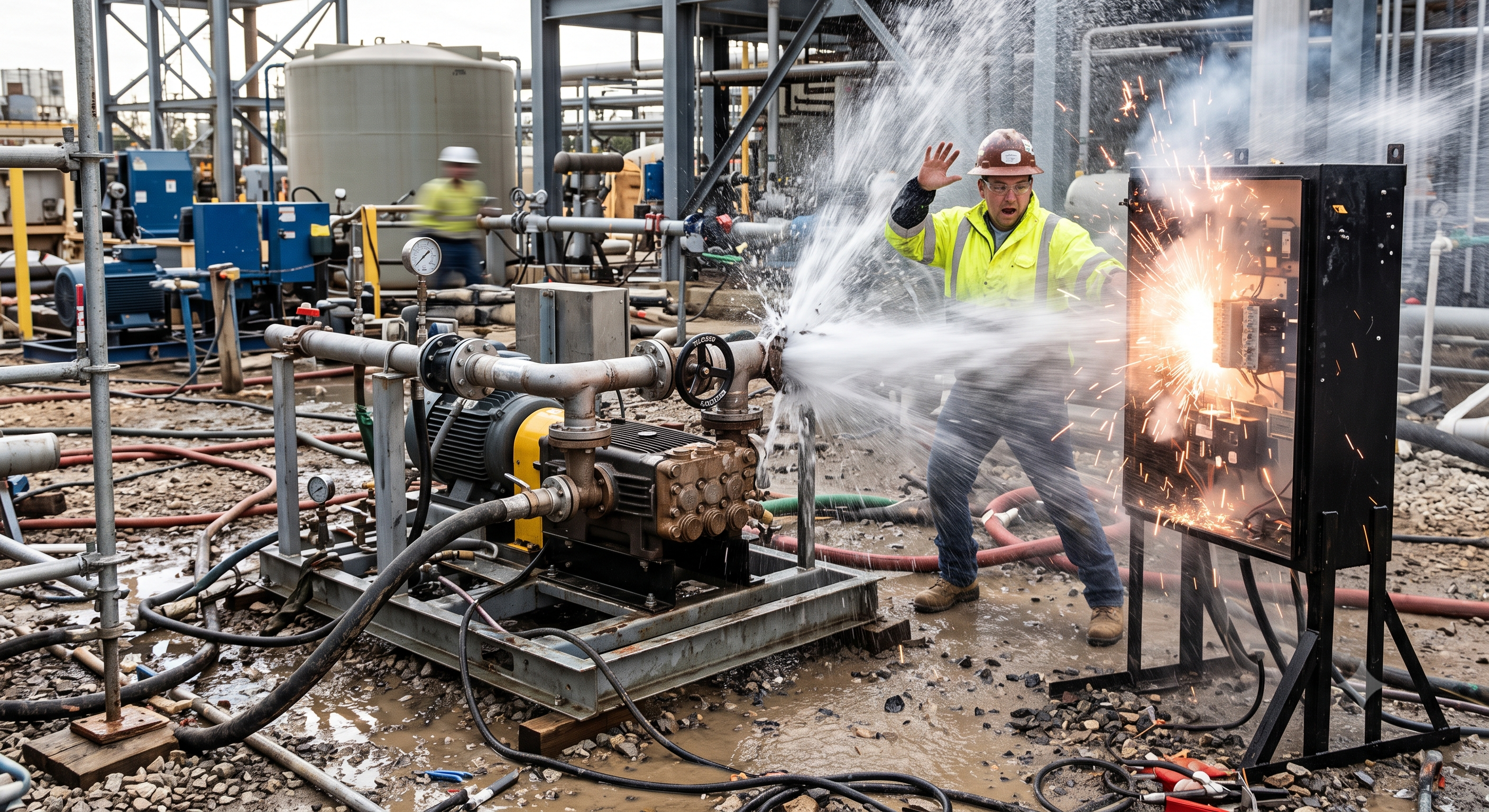
Retained AI-generated educational illustration; not an actual incident photograph.
The scenario and record comparisons are fictional teaching examples, not records of real incidents, measurements, inspections, signatures or approvals.
| Item | Fictional scenario |
|---|---|
| Initial situation | A team prepares a positive-displacement pump for a later water-pressure test. |
| Changed condition | The discharge route has not been walked down and a temporary electrical panel lies in the possible leak path. |
| Failure path | Starting against an obstructed route can raise pressure rapidly; failure may release a jet towards electrical equipment. |
| Possible outcome | Injection, impact and electrical injury are possible consequences, not reported events or verified measurements. |
| Prevention barrier | Hold the start, establish the relief and discharge paths, separate electrical equipment and record the actual release checks. |
Failure mechanisms
A positive-displacement pump continues displacing fluid when its outlet is restricted; pressure is limited by the system response, protection and failure modes, not by the nameplate alone. P = F/A is not a time-dependent surge calculation, and pressure does not universally rise exponentially. Verify the weakest pressure-rated component, suitable relief capacity and settings, and an unobstructed safe relief route. A regulator or bypass is not automatically an independent safety device.
Pulsation and vibration can impose cyclic loads on fittings and supports. Foundation preparation, anchoring, approved shims or isolation mounts, alignment and independently supported pipework must suit the actual package; a soft pad alone is not a stability design. Never use pipe flanges to pull a misaligned pump into place. Inspect connectors, seals and any specified restraint as an assembly; restraint limits movement but does not stop a fluid jet.
A pressure gauge at zero can have an isolated or blocked sensing connection. Confirm range, condition, current calibration status under the applicable programme and the live measurement path; a visual zero check is not calibration. Before intervention, isolate every energy source, release pressure through a safe path and verify the relevant pockets. Account for possible pressure return from connected equipment, elevation or trapped sections.
Electrical release includes suitable supply and protection, protective-conductor continuity, cable routing and a competent person’s checks. A residual-current device does not make a wet panel safe or guarantee protection against every electrical fault. Confirm rotation using the manufacturer’s safe procedure; uncoupled jogging is not a universal legal step. Control access to rotating parts, and restore guards before normal operation.
Separate mechanical completion, low-load functional checks and pressure-test authority. Verify inlet supply, lubrication, priming or venting, valve alignment, relief path, monitoring and stopping arrangements before the permitted check. Stop for abnormal vibration, leakage, pressure or inlet starvation. Establish exclusion from credible failure energy, jets and fragments; a fixed 10 m or 30 ft radius is not proof of safety.
Pump lifting eyes may be rated for the pump alone, not the motor and skid: verify designated points for the complete package. Follow the actual model’s limits for recirculation; prolonged bypass operation can heat the fluid. Do not run dry or assume a bypass path is suitable merely because a valve is open.
Decision sequence
| Decision stage | What to verify |
|---|---|
| Known facts | Identify model, duty, connected limits and test boundary. |
| Unresolved matters | Compare the actual relief, discharge and inlet routes with the approved arrangement. |
| Reason to hold | Withhold energisation if electrical, guarding or pressure-path evidence is missing. |
| Required evidence | Isolate and correct discrepancies before a controlled check. |
| Restart decision | Record actual results, open defects and the separate authority for any pressure test. |
5. Conditional decisions and common errors
| Condition | Action | Evidence | Proceed when |
|---|---|---|---|
| Pressure path unclear | Trace valves, bypass and relief route | Circuit, valve lineup and relief data | Safe route verified |
| Power not released | Have competent staff verify supply | Isolation and protection records | Electrical release recorded |
| Rotation unconfirmed | Apply the model-specific check | Procedure, guards and observation | Rotation safely confirmed |
| Gauge reads zero | Isolate, drain and prove pockets | Test path and pressure evidence | Safe state verified |
Similar situations, different decisions
The scenario and record comparisons are fictional teaching examples, not records of real incidents, measurements, inspections, signatures or approvals.
| Comparison | Situation A | Situation B |
|---|---|---|
| Relief | A valve is fitted | Capacity, setting and discharge route suit the complete system |
| Gauge | Pointer appears at zero | Usable sensing path and valid calibration evidence checked |
| Completion | Motor runs without alarm | Actual checks accepted and pressure-test authority separately issued |
6. Roles and responsibilities
| Role | Responsibility |
|---|---|
| Work supervisor | Define pump duty, equipment boundaries, safe operating limits and competent personnel. Identify federal or provincial/territorial jurisdiction and applicable electrical authority. |
| Technical reviewer | Plan lifting, landing, foundation and independently supported connections. |
| Work crew | Release electrical work only after isolation, protection and rotation arrangements are verified. |
| Inspector / assessor | Control the initial check from a protected location with clear stop criteria. |
| Release / handover authority | Accept documented checks and open-defect disposition; retain a separate pressure-test decision. |
Supervision, records, handover
| Job stage | Technical and procedural controls | Site verification |
|---|---|---|
| Define boundaries | 1. Agree installation scope2. Separate pressure-test permit3. Assign interface owners | 1. Duty specification2. Boundary drawing3. Responsibility record |
| Release lifting | 1. Approve package lifting plan2. Verify rigging selection3. Release landing area | 1. Package mass2. Designated lifting points3. Rigging inspection record |
| Accept pressure circuit | 1. Review whole-circuit ratings2. Check relief design basis3. Accept assembly evidence | 1. Component rating register2. Relief arrangement3. Assembly inspection |
| Release electrical work | 1. Confirm authorised personnel2. Review isolation evidence3. Require protection results | 1. Supply identification2. Electrical competence3. Protection test record |
| Permit function check | 1. Agree guarded check method2. Witness readiness review3. Set stop criteria | 1. Model rotation procedure2. Valve lineup record3. Inlet and stop criteria |
| Decide handover | 1. Review isolation and venting2. Record separate test release3. Assign outstanding defects | 1. Safe-state evidence2. Test boundary acceptance3. Defect ownership record |
7. Hold points and record comparison
| Hold point | Evidence before release | Confirmation / approval |
|---|---|---|
| Start | Receipt, lifting, positioning, connection and controlled initial checks of an identified electrically driven high-pressure pump package. Confirm whether it is a positive-displacement unit, the actual fluid and duty, all connected equipment and the boundary between installation and the separately authorised test. | |
| HP-1 Unload pump | Centre of gravity · Rigging identification · Landing condition · Signal arrangements | |
| HP-2 Connect pressure circuit | Assembly specifications · Relief path and setting · Joint assembly record · Gauge suitability | |
| HP-3 Connect electricity | Supply identification · Isolation verification · Protection test record · Cable routing inspection | |
| HP-4 Stop and hand over | Isolation register · Depressurisation evidence · Defect and repair record · Handover decision |
Complete after actual checks. Recheck after changes, defects or shift handover.
Record comparison examples
The scenario and record comparisons are fictional teaching examples, not records of real incidents, measurements, inspections, signatures or approvals.
The boxes are static record prompts, not interactive or saved approvals. A tick does not establish suitability or permission to restart. Record the evidence, person, time and unresolved issues; retain the change history.
| Record type | Insufficient record | Record checklist |
|---|---|---|
| Duty | Only marked OK | □ Model and manual□ Pressure and flow limits□ Mass and lifting plan□ Permit and interfaces |
| Relief | Only marked OK | □ Assembly specifications□ Relief path and setting□ Joint assembly record□ Gauge suitability |
| Power | Only marked OK | □ Supply identification□ Isolation verification□ Protection test record□ Cable routing inspection |
| Handover | Only marked OK | □ Isolation register□ Depressurisation evidence□ Defect and repair record□ Handover decision |
8. Site checklist and emergency response
| Check item | Result | Person / action |
|---|---|---|
| □ Define duty: Model and manual | ||
| □ Unload pump: Centre of gravity | ||
| □ Position and support: Foundation condition | ||
| □ Connect pressure circuit: Assembly specifications | ||
| □ Connect electricity: Supply identification | ||
| □ Verify rotation: Rotation procedure | ||
| □ Check low-load function: Valve lineup | ||
| □ Stop and hand over: Isolation register | ||
| □ Release / handover authority |
Stop work
Stop for leakage, unexpected hose movement, loss of inlet supply, abnormal noise or vibration, unstable pressure, failed protection, wet electrical equipment or entry into the exclusion zone. Do not touch suspected leaks, tighten live joints or adjust relief settings to overcome a fault.
Emergency response
Stop remotely if safe, withdraw from jets and electrical exposure, raise the site alarm and maintain exclusion. Isolate the power before approaching wet equipment. Suspected fluid injection needs immediate professional medical attention even when the wound appears small; provide fluid information. Follow the site rescue plan without improvised entry.
9. Sources and review limits
2026-10-11
| Source | Scope and limitations |
|---|---|
| CCOHS — Electrical safety | Official guidance on qualified persons, damaged wiring, wet conditions and jurisdiction-specific code adoption. |
| CCOHS — Lockout/Tag out | Equipment-specific isolation, stored-energy control and verification guidance. |
| HSE GS4 — Pressure testing | Reviewed written test systems, rated fittings, guarding, venting and safe depressurisation. UK guidance; separate test plan required. |
| Cat Pumps — 1CX manual | Reviewed installation and safety sections. Illustrative 1CX instructions only; identify the actual pump and applicable manual before use. |
This is reference content written and revised with AI. It has not been verified or approved by a professional. Review by a suitably qualified professional and site authorisation are required before use.
10. PDF guidance and FAQ
PDF A covers basic task controls; B focuses on technical failures; C covers supervision, records and handover. The article has eight stages with four items per main cell; each PDF has six key stages with three items per main cell. P/S/R/A, measurements, confirmations and signatures remain blank for actual site assessment.
Content group ID
jsa-pump-installation
Does a gauge at zero prove depressurisation?
No. A blocked or isolated sensing line may hide trapped pressure; use the planned isolation and verification method.
Must every motor be jogged uncoupled?
No. Use the actual manufacturer’s safe rotation-check procedure and suitable guarding.
Is a 10 m barrier sufficient?
Not by itself. Establish the danger zone and shielding from credible failure modes and energy.
Does this checklist authorise the pressure test?
No. The test needs its own method, limits, safeguards and actual release.
Has a professional verified or approved this document?
No. Public sources and editorial, layout and consistency checks were reviewed using AI. No site inspection or professional technical approval has been performed. Obtain appropriate professional review before use.
11. Revision history and authorship
This is reference content written and revised with AI. It has not been verified or approved by a professional. Review by a suitably qualified professional and site authorisation are required before use.
| Date | Version | Change | Review status |
|---|---|---|---|
| 2026-09-13 | Original version unmarked | Original preserved | No professional approval |
| 2026-10-11 | 1.1 | Decisions, records, JSA and PDFs revised | No professional approval |
Original useful handling, levelling, connections, electrical checks, valve alignment and housekeeping controls are retained. Unsupported field-validation and automatic engineering-calculation claims are replaced with AI-reference and qualified-review notices. The unverified incident is explicitly hypothetical; prefabricated risk scores are blank. Universal gasket types, two-person staffing, uncoupled-jog mandates, 10 m/30 ft boundaries and fixed calibration periods are replaced with evidence-based selections. A zero indication is distinguished from calibration and proof of pressure release. The Canadian original’s gauge-path, relief and rigging checks are preserved. Its two-master-gauge/30-day calibration rule, above-1000-kPa dual-leg restraint rule and locked-fully-open bypass are not treated as universal requirements; the actual instrument programme, restraint design and pump circuit govern. CSA Z462 was not verified as mandating an uncoupled jog for every pump. The claim of universally exponential pressure rise is corrected.