A closed valve and a zero gauge do not establish that a flange is safe to open. This revision connects isolation, proof of released energy, supported separation, gasket installation and authorised reinstatement.
Identify joint → Isolate system → Prove safe state → Support and open → Inspect surfaces → Assemble joint → Test integrity → Restore service
This is reference content written and revised with AI. It has not been verified or approved by a professional. Review by a suitably qualified professional and site authorisation are required before use.
Stop work
Stop for unidentified contents, unproved isolation, blocked vents or drains, returning pressure, uncontrolled movement, incompatible parts, unsafe access or loss of communication.
1. Legal and technical scope
| Basis | Application limits |
|---|---|
| CCOHS: lockout/tag out | Official guidance on energy sources, isolation, stored energy and verification reviewed; no full CSA or provincial legal audit. |
| HSE: HSG253 | Selected HSG253 paragraphs 156, 165–175 on preparation, initial/final isolation, proving and monitoring reviewed from the official PDF. British process-isolation guidance, not local law. |
| CCOHS: Non-sparking tools | Official guidance on reduced-sparking tools, compatibility and continuing ignition hazards reviewed. Not a claim of spark-free operation. |
Canada: identify the federal, provincial or territorial jurisdiction before applying a legal requirement. CCOHS publishes national technical guidance; its guidance is not itself a universal regulation for every workplace.
CCOHS describes hazardous-energy isolation, verification and stored-energy control. The full CSA Z460 standard, adopted editions and local pressure-system rules were not reviewed. HSE is supplementary British technical guidance and does not establish Canadian legal compliance.
2. Scope and required inputs
Included scope
Identify the pipe and joint; review contents and access; isolate, drain, vent and cool; prove the boundary; support and separate; inspect and replace the gasket; complete an approved leak test and handover.
Separate review
This is not a pressure-system design, isolation certificate or test procedure. Confined-space entry, hot work, live repairs, asbestos removal and special oxygen or reactive chemical service require separate arrangements.
| Required input | What to verify |
|---|---|
| Identify joint | Joint and line identity / Fluid and temperature / Access inspection / PPE and rescue plan |
| Isolate system | Isolation register / Lock and valve identity / Safe discharge route / Temperature and contents |
| Prove safe state | Proof method and record / Atmosphere assessment / Isolation monitoring / Initial break permit |
Use actual drawings, SDS, operating conditions, manufacturer instructions and local rules. No universal valve arrangement, glove material, torque value, tightening percentages or nitrogen test is prescribed. Actual readings, signatures and approvals remain blank until performed on site.
3. Eight-stage JSA
| Job stage | Hazards and effects | Failure factors | Technical and procedural controls | Site verification | P | S | R | A |
|---|---|---|---|---|---|---|---|---|
| 1. Identify joint | 1. Wrong line opened2. Chemical exposure3. Fall from pipe rack4. Dropped tools | 1. Unverified line tag2. Unknown process fluid3. Unsafe access platform4. Unprotected area below | 1. Trace line against drawing2. Review fluid SDS and permit3. Provide safe access4. Protect people below | 1. Joint and line identity2. Fluid and temperature3. Access inspection4. PPE and rescue plan | ||||
| 2. Isolate system | 1. Unexpected flow2. Stored pressure3. Thermal release4. Backfeed through bypass | 1. Passing valve2. Unmapped dead leg3. Trapped hot liquid4. Unsecured remote valve | 1. Apply isolation plan2. Lock all relevant energy3. Drain, vent and cool safely4. Control bypasses and returns | 1. Isolation register2. Lock and valve identity3. Safe discharge route4. Temperature and contents | ||||
| 3. Prove safe state | 1. Pressure rebuild2. Hazardous atmosphere3. Injection or splash4. Unsafe blind installation | 1. Zero gauge assumed proof2. Blocked drain connection3. Isolation not monitored4. Blind fitted before proving | 1. Prove isolation at boundary2. Verify clear vent/drain path3. Monitor for pressure return4. Authorise initial line break | 1. Proof method and record2. Atmosphere assessment3. Isolation monitoring4. Initial break permit | ||||
| 4. Support and open | 1. Pipe spring or collapse2. Hand crushing3. Residual fluid splash4. Dropped heavy blind | 1. Unassessed pipe stress2. Fingers in flange gap3. Body in release path4. Inadequate lifting support | 1. Support pipe and components2. Use rated flange spreaders3. Keep clear and contain residue4. Follow planned bolt release | 1. Support and lifting plan2. Spreader seating3. First-break observations4. Stop if energy remains | ||||
| 5. Inspect surfaces | 1. Hazardous gasket dust2. Ignition of residue3. Damaged sealing face4. Exposure during cleaning | 1. Unknown old gasket2. Tool/medium incompatibility3. Aggressive scraping4. Uncontrolled solvent use | 1. Assess old gasket material2. Select suitable low-spark tools3. Clean without face damage4. Control waste and exposure | 1. Gasket material assessment2. Tool/atmosphere suitability3. Face and stud inspection4. Waste containment | ||||
| 6. Assemble joint | 1. Leak on restart2. Gasket damage3. Uneven bolt load4. Reaction-arm crushing | 1. Wrong gasket specification2. Forced pipe alignment3. Wrong torque or lubricant4. Unsafe powered-tool setup | 1. Fit specified new gasket2. Align without pulling by bolts3. Use approved tightening plan4. Control tool reaction zones | 1. Gasket and bolt identity2. Alignment and face condition3. Calibrated tool record4. Lubricant and torque record | ||||
| 7. Test integrity | 1. Stored test energy2. Gas asphyxiation3. Jet from leakage4. Unauthorised pressure rise | 1. Unapproved gas test2. Unsafe vent destination3. Close inspection at pressure4. Wrong boundary or relief | 1. Use approved test procedure2. Control medium and discharge3. Inspect from protected position4. Depressurise before repair | 1. Test boundary and permit2. Pressure device checks3. Leak-test result record4. Energy release before repair | ||||
| 8. Restore service | 1. Unexpected startup2. Wrong blind position3. Leak during warming4. Uncontrolled waste | 1. Incomplete handover2. Blind register not reconciled3. Rapid reintroduction4. Residues left on platform | 1. Reconcile locks and blinds2. Clear people and tools3. Restart under operations control4. Monitor and close handover | 1. Joint completion record2. Isolation removal approval3. Controlled startup record4. Waste and access release |
PDF A covers basic task controls; B focuses on technical failures; C covers supervision, records and handover. The article has eight stages with four items per main cell; each PDF has six key stages with three items per main cell. P/S/R/A, measurements, confirmations and signatures remain blank for actual site assessment.
4. Fictional scenario and failure mechanisms
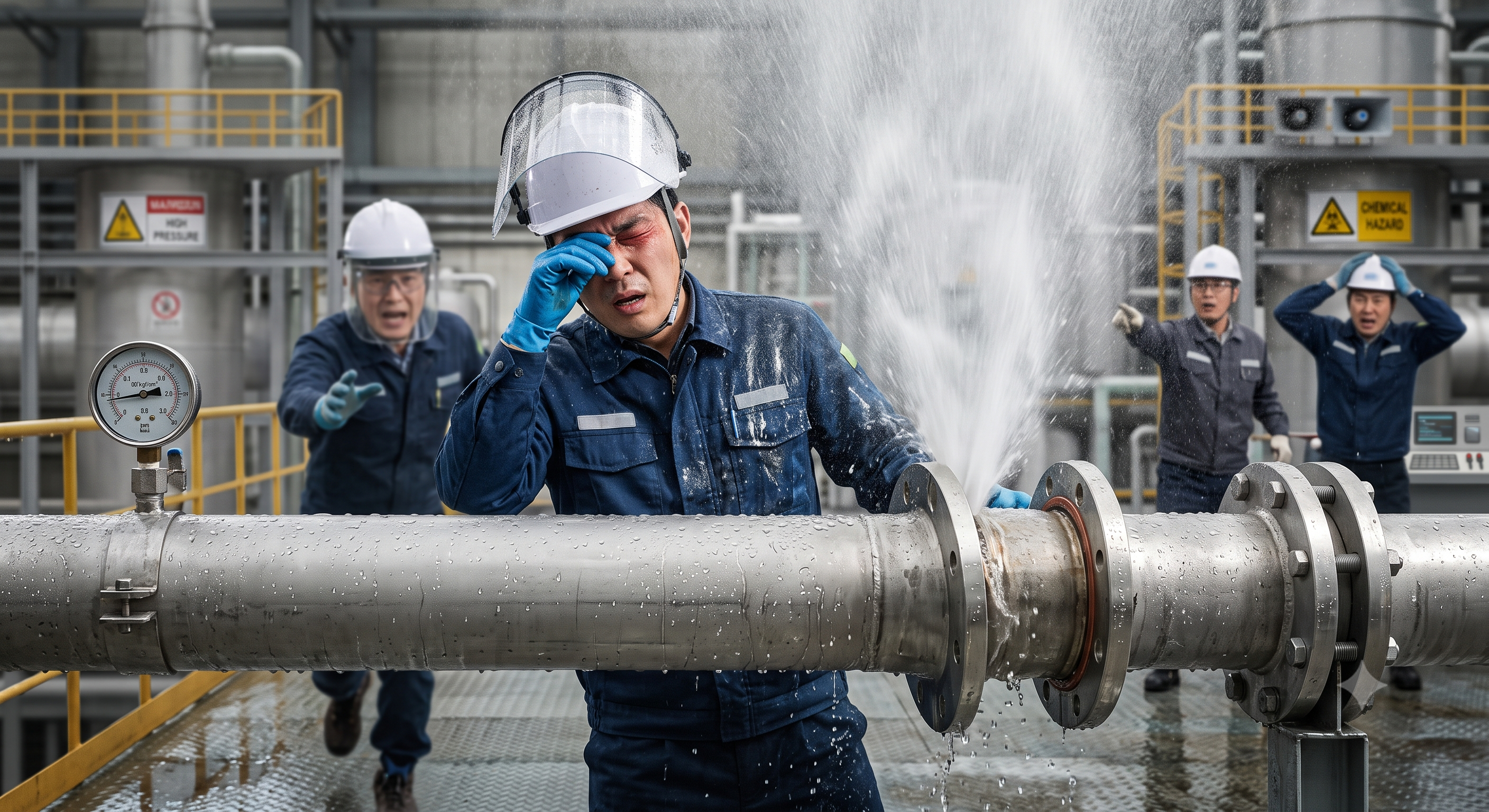
The original educational image is retained. It is not evidence of an actual incident or site suitability.
The scenario and record comparisons are fictional teaching examples, not records of real incidents, measurements, inspections, signatures or approvals.
| Item | Fictional scenario |
|---|---|
| Initial situation | Hypothetical example: a maintenance team plans to replace a flange gasket. |
| Changed condition | A gauge reads zero, but a drain may be blocked and a connected branch may feed the section. |
| Failure path | Opening the joint could release fluid, pressure or heat; the example makes no claim about a named worker or an actual injury. |
| Immediate response | Stop before loosening. Operations verifies the boundary, drainage path and residual hazards using the approved isolation procedure. |
| Release condition | Record proof, support the pipe and authorise the first break only after the responsible person accepts the conditions. |
Failure mechanisms
Pressure acting over an effective area produces force; hot or toxic contents can remain hazardous even at atmospheric pressure. PPE does not replace removal and containment of the hazard.
A gauge may indicate pressure presence but cannot alone prove its absence. Check the proving path, drains, trapped sections, bypasses and potential reaccumulation. Never crack an unverified flange to diagnose pressure.
Installing a blind itself requires a safe first opening. Prove the initial isolation before that opening, then verify and monitor the final isolation. Double-block-and-bleed and a physical blind are not interchangeable terms.
Support each part before separating it. Use suitable spreaders and retain hands outside the gap. Leaving a particular bolt as a hinge cannot guarantee a safe release direction.
Select gasket, fasteners, lubricant and tightening procedure for the actual flange and service. Never pull misaligned pipe into place with bolts.
A test needs its own accepted medium, pressure, boundary and release procedure. Gas testing adds stored-energy and possible asphyxiation hazards; nitrogen is not the automatic choice.
Decision sequence
| Decision stage | What to verify |
|---|---|
| Identify | Confirm joint ID, contents and the approved isolation boundary. |
| Hold | Stop for uncertain pressure, contents, support or energy proof. |
| Correct | Operations and competent maintenance personnel resolve the cause. |
| Verify | Record isolation, proving, components, assembly and test evidence. |
| Release | Authorise reinstatement, monitor and hand over to operations. |
5. Conditional decisions and common errors
| Condition | Action | Evidence | Proceed when |
|---|---|---|---|
| Uncertain pressure | Stop before first break. | Drain path and isolation proof | Boundary accepted |
| Pipe movement | Stop and support both sides. | Loads and support arrangement | Support checked |
| Damaged flange | Hold assembly. | Face, gasket and bolt review | Repair accepted |
| Test leak | Stop and safely depressurise. | Cause and retest procedure | Retest authorised |
Similar situations, different decisions
The scenario and record comparisons are fictional teaching examples, not records of real incidents, measurements, inspections, signatures or approvals.
| Comparison | Situation A | Situation B |
|---|---|---|
| Energy | Zero on one gauge leaves hidden assumptions. | Proving addresses blockage, trapped sections and backfeed. |
| Separation | A bolt hinge does not guarantee containment. | Support, controlled separation and exclusion follow the actual hazard. |
| Assembly | A generic torque sequence is not acceptance. | Specified components, procedure and test evidence support release. |
6. Roles and responsibilities
| Role | Responsibility |
|---|---|
| Operations authority | Identifies process connections, establishes isolation, confirms proving and authorises reinstatement. |
| Maintenance lead | Confirms access, supports, tools, gasket and assembly procedure. |
| Test responsible person | Approves test boundary, medium, pressure, exclusion and controlled release. |
| Handover receiver | Checks blind and lock reconciliation, guards, leaks and remaining restrictions. |
Supervision, records, handover
| Job stage | Technical and procedural controls | Site verification |
|---|---|---|
| Review Identify joint | 1. Record: Joint and line identity2. Record: Fluid and temperature3. Record: Access inspection | 1. PPE and rescue plan2. Provide safe access3. Protect people below |
| Review Isolate system | 1. Record: Isolation register2. Record: Lock and valve identity3. Record: Safe discharge route | 1. Temperature and contents2. Drain, vent and cool safely3. Control bypasses and returns |
| Review Prove safe state | 1. Record: Proof method and record2. Record: Atmosphere assessment3. Record: Isolation monitoring | 1. Initial break permit2. Monitor for pressure return3. Authorise initial line break |
| Review Assemble joint | 1. Record: Gasket and bolt identity2. Record: Alignment and face condition3. Record: Calibrated tool record | 1. Lubricant and torque record2. Use approved tightening plan3. Control tool reaction zones |
| Review Test integrity | 1. Record: Test boundary and permit2. Record: Pressure device checks3. Record: Leak-test result record | 1. Energy release before repair2. Inspect from protected position3. Depressurise before repair |
| Review Restore service | 1. Record: Joint completion record2. Record: Isolation removal approval3. Record: Controlled startup record | 1. Waste and access release2. Restart under operations control3. Monitor and close handover |
7. Hold points and record comparison
| Hold point | Evidence before release | Confirmation / approval |
|---|---|---|
| Start | Identify the pipe and joint; review contents and access; isolate, drain, vent and cool; prove the boundary; support and separate; inspect and replace the gasket; complete an approved leak test and handover. | |
| HP-1 Isolate system | Isolation register · Lock and valve identity · Safe discharge route · Temperature and contents | |
| HP-2 Prove safe state | Proof method and record · Atmosphere assessment · Isolation monitoring · Initial break permit | |
| HP-3 Support and open | Support and lifting plan · Spreader seating · First-break observations · Stop if energy remains | |
| HP-4 Restore service | Joint completion record · Isolation removal approval · Controlled startup record · Waste and access release |
Complete after actual checks. Recheck after changes, defects or shift handover.
Record comparison examples
The scenario and record comparisons are fictional teaching examples, not records of real incidents, measurements, inspections, signatures or approvals.
The boxes are static record prompts, not interactive or saved approvals. A tick does not establish suitability or permission to restart. Record the evidence, person, time and unresolved issues; retain the change history.
| Record type | Insufficient record | Record checklist |
|---|---|---|
| Isolate system | Tick without joint ID or evidence | □ Isolation register□ Lock and valve identity□ Safe discharge route□ Temperature and contents |
| Prove safe state | Tick without joint ID or evidence | □ Proof method and record□ Atmosphere assessment□ Isolation monitoring□ Initial break permit |
| Assemble joint | Tick without joint ID or evidence | □ Gasket and bolt identity□ Alignment and face condition□ Calibrated tool record□ Lubricant and torque record |
| Restore service | Tick without joint ID or evidence | □ Joint completion record□ Isolation removal approval□ Controlled startup record□ Waste and access release |
8. Site checklist and emergency response
| Check item | Result | Person / action |
|---|---|---|
| □ Identify joint: Joint and line identity | ||
| □ Isolate system: Isolation register | ||
| □ Prove safe state: Proof method and record | ||
| □ Support and open: Support and lifting plan | ||
| □ Inspect surfaces: Gasket material assessment | ||
| □ Assemble joint: Gasket and bolt identity | ||
| □ Test integrity: Test boundary and permit | ||
| □ Restore service: Joint completion record | ||
| □ Release / handover authority |
Stop work
Stop for unidentified contents, unproved isolation, blocked vents or drains, returning pressure, uncontrolled movement, incompatible parts, unsafe access or loss of communication.
Emergency response
Stop work, alarm and clear the release area. Isolate remotely only under the emergency plan. Do not approach a pressurised leak or enter a suspect atmosphere for an improvised rescue. Use the site spill, fire, exposure and rescue arrangements.
9. Sources and review limits
2026-10-08
| Source | Scope and limitations |
|---|---|
| CCOHS: lockout/tag out | Official guidance on energy sources, isolation, stored energy and verification reviewed; no full CSA or provincial legal audit. |
| HSE: HSG253 | Selected HSG253 paragraphs 156, 165–175 on preparation, initial/final isolation, proving and monitoring reviewed from the official PDF. British process-isolation guidance, not local law. |
| CCOHS: Non-sparking tools | Official guidance on reduced-sparking tools, compatibility and continuing ignition hazards reviewed. Not a claim of spark-free operation. |
This is reference content written and revised with AI. It has not been verified or approved by a professional. Review by a suitably qualified professional and site authorisation are required before use.
10. PDF guidance and FAQ
PDF A covers basic task controls; B focuses on technical failures; C covers supervision, records and handover. The article has eight stages with four items per main cell; each PDF has six key stages with three items per main cell. P/S/R/A, measurements, confirmations and signatures remain blank for actual site assessment.
Content group ID
jsa-pipe-disassembly
Is a zero gauge enough?
No. Verify the proving route, isolation and potential trapped or returning energy through the approved procedure.
When is a blind inserted?
Only after the initial isolation is proved safe for the first opening; then verify the final boundary.
Are non-sparking tools spark-free?
No. They can reduce ignition risk but still require compatible selection, clean tools and atmosphere controls.
Must every gasket receive a nitrogen test?
No. Use the approved test method for the system; gas tests need additional stored-energy and atmosphere controls.
Has a professional verified or approved this document?
No. Public sources and editorial, layout and consistency checks were reviewed using AI. No site inspection or professional technical approval has been performed. Obtain appropriate professional review before use.
11. Revision history and authorship
This is reference content written and revised with AI. It has not been verified or approved by a professional. Review by a suitably qualified professional and site authorisation are required before use.
| Date | Version | Change | Review status |
|---|---|---|---|
| 2026-09-12 | Original version unmarked | Original preserved | No professional approval |
| 2026-10-08 | 1.1 | Decisions, records, JSA and PDFs revised | No professional approval |
Retains permits, SDS, isolation, pipe support, flange tools, gasket checks and handover. Corrects the unsafe order of blind installation, the zero-gauge assumption, universal bolt-hinge and torque rules, automatic nitrogen testing and spark-free tool claims. The injury story is explicitly hypothetical; no professional validation or guaranteed legal compliance is claimed.