Control the temporary load path before allowing the next movement. This revision links the existing crane-specific hazards to evidence at connection opening, each hydraulic stroke, mast insertion and final release. The eight rows group activities; they do not prescribe the mechanical sequence for an unidentified crane.
This is reference content written and revised with AI. It has not been verified or approved by a professional. Review by a suitably qualified professional and site authorisation are required before use.
Stop work
Stop for missing support confirmation, abnormal pressure or movement, guide binding, loss of communication, weather outside the approved envelope, an incomplete connection or entry into the exposure zone. Stop progressing the sequence; keep the system in its prescribed holding condition.
1. Legal and technical scope
| Basis | Application limits |
|---|---|
| Ontario - O. Reg. 213/91 | Official indexed text: 157(13) support/tie inspections, 157.1 plumb, 157.2 climbing and 158 inspections. Current project application must be checked. |
| Ontario - crane technical guideline | Official search extract confirms its scope and that guidance does not replace the Act/regulation; full live page unavailable. |
Canada: identify the governing province or territory; Ontario is the example, not a Canada-wide rule. The official indexed O. Reg. 213/91 text confirms section 157.2 refers to CSA Z248-17 clauses 5.1, 5.8 and 5.9. A newer CSA catalogue edition does not automatically replace the incorporated edition. The live Ontario page returned an access error; its indexed official text was reviewed. Licensed CSA text was not reviewed.
2. Scope and required inputs
Use the exact manufacturer climbing manual, approved configuration and jurisdiction-specific engineering documents. No actual model manual or site calculations were supplied. Do not infer wind limits, torque, support capacity, free-standing height or a pin-removal sequence from this guide. A support may carry hydraulic load during a prescribed stroke; mechanical transfer is required at the stages specified for that system.
| Required input | What to verify |
|---|---|
| Plan | Does the procedure match the actual crane and climbing system?; Are required engineering reports signed and available?; Are qualifications and authorizations verified?; Are simultaneous operations controlled? |
| Weather | Are current and forecast conditions acceptable?; Is the anemometer functioning at the specified location?; Are stop and securing criteria understood?; Does the barricade match the approved drawing? |
| Inspect | Is the required climbing-system inspection complete?; Are hydraulic test results acceptable?; Are guide clearances within the specified tolerance?; Are all safety-critical defects closed? |
| Balance | Is the trolley at the recorded balance radius?; Is the specified slewing restraint fully effective?; Are ballast and counterweights correct?; Has the balance condition received independent confirmation? |
| Each stroke | Are both sides fully and symmetrically supported?; Are pressure and cylinder position normal?; Are personnel clear of pinch and shear zones?; Has the stroke hold point been signed? |
| Insert | Is the correct mast section identified?; Are rigging and transfer devices inspected?; Are end stops and retainers installed?; Are hands kept outside crush zones? |
| Connect | Are component identity and condition verified?; Is tool calibration current?; Are all connections complete and retained?; Has independent verification been documented? |
| Release | Does the final configuration match the approved plan?; Are tools and temporary devices accounted for?; Are inspections, tests and logs complete?; Has return to service been formally authorized? |
A. Work covered by this guide
This guide covers a planned increase or decrease in tower height using an internal or external climbing system.
Typical activities include:
- Preparing and inspecting the climbing system
- Establishing the specified balance condition
- Temporarily releasing load-bearing tower connections
- Hydraulically raising or lowering the upper crane assembly
- Transferring the load to mechanical climbing supports
- Hoisting and inserting or removing a mast section
- Installing structural pins, bolts or other connections
- Restoring the complete structural load path
- Conducting required inspection and testing
- Issuing the return-to-service authorization
B. Work requiring separate engineering or assessment
Do not apply this guide without additional review where the work involves:
- A different crane or climbing-system model
- An unapproved mast section or connection component
- Foundation, shoring, bracing or tie-in alteration
- Removal or relocation of a tie-in
- Repair or modification of a load-bearing component
- Deviation from the manufacturer’s sequence
- Non-standard jib, counter-jib, ballast or counterweight configuration
- An overlapping-crane or restricted-slewing arrangement
- A configuration outside the approved free-standing or tied height
- Weather or environmental conditions outside the approved procedure
C. Minimum PTW attachments
Crane identification
- Manufacturer, model, serial number and year
- Current and proposed tower height
- Jib and counter-jib configuration
- Ballast and counterweight schedule
- Climbing-frame and hydraulic-system identification
Technical documents
- Current manufacturer operating instructions
- Current erection and climbing instructions
- Approved climbing sequence
- Manufacturer technical bulletins
- Mast-section and connection-hardware schedule
- Balance-load and trolley-position data
Engineering documents
- Foundation design and verification
- Shoring, bracing and tie-in drawings
- Supporting-structure assessment
- Temporary climbing-condition verification
- Permitted tower heights and tie-in spacing
- Approved deviations and written engineering instructions
Safety documents
- Site-specific hazard assessment or JSA
- Erection and climbing plan
- Exclusion-zone drawing
- Communication and signalling plan
- Fall-protection plan
- Rescue plan
- High-risk work permit and hold-point sheet
Inspection and personnel records
- Required engineering inspection reports
- Climbing-system inspection report
- Maintenance and defect-closure records
- Measuring-tool and torque-tool calibration records
- Operator, erector, rigger and signaller qualifications
- Site orientation and task-specific training records
3. Eight-stage JSA
| Job stage | Hazards and effects | Failure factors | Technical and procedural controls | Site verification | P | S | R | A |
|---|---|---|---|---|---|---|---|---|
| 1. Plan | 1. Incorrect procedure or configuration causing structural instability2. Missing engineering inspection or approval3. Unqualified supervision or workers4. Conflicting work beneath or adjacent to the crane | 1. Generic JSA used without crane identification2. Outdated manufacturer procedure3. Unresolved conflict between drawings and field conditions4. Required reports absent from the project | 1. Identify crane, serial number, configuration and climbing system2. Confirm governing jurisdiction and applicable CSA edition3. Attach current manufacturer, engineering and inspection documents4. Name the person directing the operation and all required competent or qualified persons | 1. Does the procedure match the actual crane and climbing system?2. Are required engineering reports signed and available?3. Are qualifications and authorizations verified?4. Are simultaneous operations controlled? | ||||
| 2. Weather | 1. Wind-induced rotation, racking or loss of balance2. Lightning, poor visibility, ice or slippery surfaces3. Falling materials striking workers or the public4. Unauthorized entry into the credible collapse zone | 1. Using a generic 32 km/h limit without confirmation2. Relying on ground-level observation3. Undefined gust and averaging criteria4. Fixed-radius barricade unrelated to actual exposure | 1. Enter the controlling manufacturer or engineered wind criteria2. Define measurement location, units, averaging period, warning and stop levels3. Establish the exclusion zone from drop, swing, transfer and collapse envelopes4. Provide barricades, signage and access control | 1. Are current and forecast conditions acceptable?2. Is the anemometer functioning at the specified location?3. Are stop and securing criteria understood?4. Does the barricade match the approved drawing? | ||||
| 3. Inspect | 1. Damaged mast or climbing-frame member2. Hydraulic hose, valve or cylinder failure3. Guide-roller or climbing-support failure4. Failure of access platform or fall-protection component | 1. Inspection performed by an unauthorized person2. Defects accepted without documented disposition3. Pressure-holding or leak-down test omitted4. Guide-roller clearances not measured | 1. Complete all regulatory, engineering and manufacturer-required inspections2. Check cylinders, hoses, fittings, valves, supports, pawls, dogs, rollers and rails3. Function-test controls, indicators, emergency stop and communication systems4. Quarantine defective or unidentified components | 1. Is the required climbing-system inspection complete?2. Are hydraulic test results acceptable?3. Are guide clearances within the specified tolerance?4. Are all safety-critical defects closed? | ||||
| 4. Balance | 1. Eccentric loading causing mast binding or frame distortion2. Unintended slewing during a disconnected condition3. Incorrect counterweight, ballast or balance load4. Collision with structures or another crane | 1. Trolley position estimated instead of measured2. Normal slew brake assumed to be sufficient3. Balance condition checked by only one person4. Configuration differs from the approved plan | 1. Set counterweight, ballast, trolley and balance load exactly as specified2. Orient the jib in the approved climbing direction3. Apply the manufacturer-specified slewing restraint4. Verify level, alignment and load response before releasing structural connections | 1. Is the trolley at the recorded balance radius?2. Is the specified slewing restraint fully effective?3. Are ballast and counterweights correct?4. Has the balance condition received independent confirmation? | ||||
| 5. Each stroke | 1. Slip of a climbing pawl, dog or support shoe2. Cylinder side loading, buckling or over-travel3. Guide-roller derailment or frame racking4. Crushing, shearing and fall hazards | 1. Load transferred before full mechanical seating2. Assembly supported only by hydraulic pressure3. Work continues after pressure loss, noise or binding4. Workers remain in the line of movement | 1. Follow the approved connection-release and jacking sequence2. Use one designated command authority3. Stop at every stroke and confirm all mechanical load paths4. Install specified pins, wedges, retainers or secondary locks before hydraulic unloading | 1. Are both sides fully and symmetrically supported?2. Are pressure and cylinder position normal?3. Are personnel clear of pinch and shear zones?4. Has the stroke hold point been signed? | ||||
| 6. Insert | 1. Rigging failure or dropped mast section2. Collision with tower, frame or structure3. Failure of transfer trolley or end restraint4. Hand injury at connection faces | 1. Incorrect mast-section identity or weight2. Uninspected rigging or transfer equipment3. Alignment forced by unauthorized crane movement4. Hands placed between structural interfaces | 1. Verify mast-section compatibility, weight and lifting points2. Inspect the hoist, transfer equipment, rigging and end stops3. Use taglines, guide pins and approved alignment tools4. Secure the section against unintended movement before releasing rigging | 1. Is the correct mast section identified?2. Are rigging and transfer devices inspected?3. Are end stops and retainers installed?4. Are hands kept outside crush zones? | ||||
| 7. Connect | 1. Tower separation due to incomplete or incorrect connections2. Bolt, pin or thread failure3. Incorrect preload from lubrication or tool error4. Dropped tools and connection components | 1. Generic torque value substituted2. Impact wrench treated as final verification3. Unidentified or non-compliant hardware used4. Matchmark treated as proof of preload | 1. Use approved components meeting specified condition and reuse criteria2. Apply the required lubrication, sequence, torque, tension or pin-retention method3. Use suitable calibrated tools4. Complete an independent connection inspection and retain the record | 1. Are component identity and condition verified?2. Is tool calibration current?3. Are all connections complete and retained?4. Has independent verification been documented? | ||||
| 8. Release | 1. Operation with incomplete structural connections2. Loose materials or tools remaining aloft3. Incorrect limits, indicators or safety devices4. Use before required inspection or testing | 1. Verbal completion report only2. Exclusion zone removed prematurely3. Crane configuration and logs not updated4. Outstanding defects accepted without authorization | 1. Account for personnel, tools, components and temporary equipment2. Restore guards, limits, indicators and operating systems3. Complete required engineering inspection, operational test and documentation4. Issue written return-to-service authorization | 1. Does the final configuration match the approved plan?2. Are tools and temporary devices accounted for?3. Are inspections, tests and logs complete?4. Has return to service been formally authorized? |
PDF A covers basic task controls; B focuses on technical failures; C covers supervision, records and handover. The article has eight stages with four items per main cell; each PDF has six key stages with three items per main cell. P/S/R/A, measurements, confirmations and signatures remain blank for actual site assessment.
Use the exact manufacturer climbing manual, approved configuration and jurisdiction-specific engineering documents. No actual model manual or site calculations were supplied. Do not infer wind limits, torque, support capacity, free-standing height or a pin-removal sequence from this guide. A support may carry hydraulic load during a prescribed stroke; mechanical transfer is required at the stages specified for that system.
4. Fictional scenario and failure mechanisms
The scenario and record comparisons are fictional teaching examples, not records of real incidents, measurements, inspections, signatures or approvals.
The original educational image is retained. It is not evidence of an actual incident or site suitability.
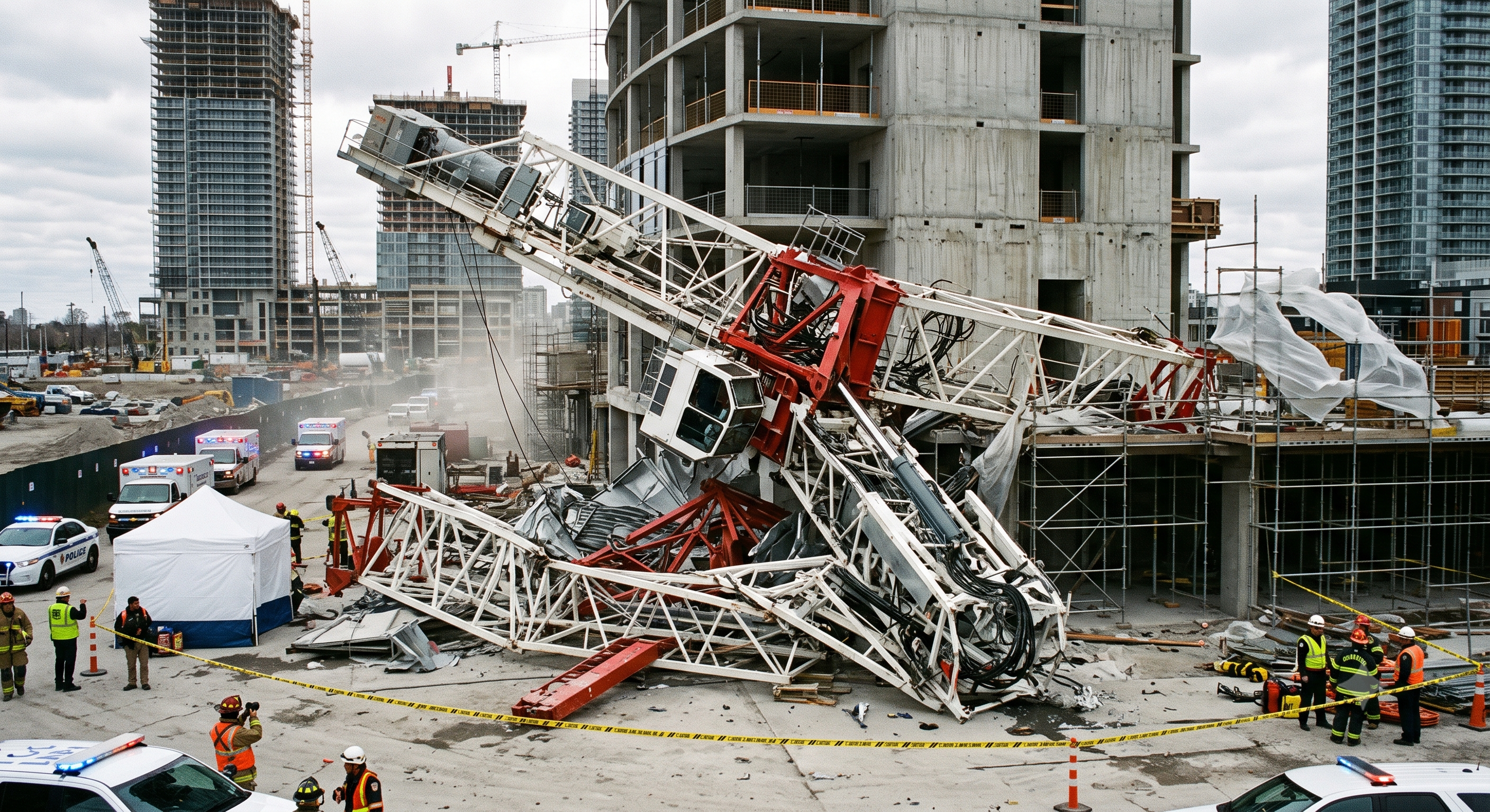
Important notice: The following Toronto scenario is hypothetical and is provided solely for training, hazard assessment and barrier analysis. The image is an illustrative representation. Neither the scenario nor the image may be presented as an actual accident, Ministry investigation, court finding or regulatory enforcement case.
A. Hypothetical event sequence
Initial condition
- High-rise construction project in Toronto, Ontario
- Hammerhead tower crane undergoing a planned top-climbing operation
- Proposed increase in tower height from 55 metres to 70 metres
- Second additional mast section positioned for transfer
- Climbing frame using a central hydraulic cylinder
Weather deviation
- Wind gusts increase to 42 km/h during a hydraulic stroke.
- The value is not treated as a universal Canadian statutory limit.
- It exceeds the lower project-specific limit entered from the manufacturer’s procedure.
- The operation continues because of schedule pressure.
Incorrect balance condition
- A specified balance load is suspended from the hook.
- The trolley is not positioned at the exact approved radius.
- The balance condition is not independently verified.
- Eccentric loading develops across the climbing frame.
Ineffective slewing restraint
- The crane-specific positive slewing restraint is not fully applied.
- The upper crane assembly relies on a normal operating brake not approved as the sole climbing restraint.
- A gust rotates the jib away from the approved climbing orientation.
Guide-system failure
- Torsion and lateral reaction forces develop in the climbing frame.
- A windward guide-roller assembly becomes overloaded.
- The roller axle fails and the frame racks diagonally.
Loss of mechanical support
- One climbing support loses full engagement with its mast support point.
- The upper assembly dynamically transfers load to the extended cylinder.
- The cylinder is subjected to unintended lateral loading.
- The cylinder buckles and the climbing assembly moves downward uncontrollably.
Credible consequences
- Fatal or life-altering injuries to personnel in the climbing frame
- Falling steel and tools entering lower work areas
- Damage to scaffolds, hoists and temporary structures
- Partial or complete loss of crane stability
- Exposure of workers or the public outside an undersized exclusion zone
B. Structural and mechanical analysis
Centre-of-gravity and moment equilibrium
- Trolley position and suspended balance load affect the resultant moment of the upper crane assembly.
- An incorrect position creates horizontal reaction forces at the guide system.
- Those forces may overload rollers, axles, frame members and tower chords.
Hydraulic cylinder behaviour
- A long-stroke cylinder becomes a slender compression member when extended.
- Unintended lateral loading reduces its resistance to buckling.
- The cylinder must not be used as a substitute for the designed guide system or mechanical support path.
Mechanical load transfer
- Hydraulic pressure is not automatically an approved long-term mechanical support.
- Climbing dogs, pawls, shoes or other supports must seat as specified.
- Unequal seating can produce impact, torsion and local overload.
Wind-induced torsion
- The jib and counter-jib create large wind-exposed areas.
- Their lever arms produce torque about the tower axis.
- The temporary climbing configuration may have less torsional restraint than the completed tower.
Dynamic amplification
- Slippage or sudden load transfer can produce forces substantially greater than the static load.
- Supports must be verified before hydraulic unloading.
- A support must never be manually repositioned while carrying load.
C. Failed-barrier analysis
| Protective Barrier | Failure Mechanism | Required Prevention |
|---|---|---|
| Approved climbing procedure | Generic documents did not control the actual crane configuration. | Use the current manufacturer procedure and site-specific engineered climbing package. |
| Wind control | Work continued above the project-specific limit. | Define measurement method, warning level, stop level, securing state and restart criteria. |
| Moment balancing | Trolley position was estimated and not independently checked. | Measure the position and verify the balance condition before releasing connections. |
| Slewing restraint | An ordinary operating brake was substituted for the required restraint. | Apply and verify the crane-specific restraint before structural disconnection. |
| Mechanical support | One support did not achieve complete engagement. | Treat every load-path transfer as a documented permit hold point. |
| Stop-work control | Schedule pressure overrode an observable unsafe condition. | Give the designated supervisor and every exposed worker clear stop-work authority. |
| Exclusion zone | The barricade did not cover the credible impact area. | Base the boundary on drop, swing, transfer and structural-collapse envelopes. |
| Emergency securing plan | The crew had no verified procedure for securing a partially climbed crane. | Include the manufacturer-approved interruption and securing sequence in the permit package. |
D. Principal lessons
- A wind value is meaningful only when its source, measurement location and averaging method are defined.
- The balance condition must be measured and independently confirmed.
- The specified slewing restraint must be effective before load-bearing connections are released.
- Every hydraulic stroke and mechanical load transfer requires a hold point.
- Mechanical supports must not be adjusted manually while loaded.
- Schedule pressure cannot replace technical acceptance or regulatory approval.
- The emergency plan must address a crane stopped in a temporary climbing condition.
5. Conditional decisions and common errors
| Condition | Action | Evidence | Proceed when |
|---|---|---|---|
| Before opening | Balance, restraint and temporary support not confirmed | Keep connections intact; resolve missing evidence | All three verified |
| Every stroke | A support is only partly seated | Stop; use the model contingency | All required seats confirmed |
| Section transfer | Section aligned but not positively retained | Keep approved handling support in place | Restraint accepted |
| Interrupted climb | Weather recovers but defect remains | Keep work suspended; inspect the affected state | Cause and hold points closed |
| Return to service | Bolts complete but tests pending | Retain operational prohibition | Required inspections accepted |
Similar situations, different decisions
| Comparison | Situation A | Situation B |
|---|---|---|
| Balance | A level reading alone | Model method, load/radius, orientation and checker recorded |
| Support | Pressure appears steady | Each specified bearing and retainer checked at the named stroke |
| Connection | Paint mark present | Hardware, method, tool and acceptance result traceable |
| Handover | Crew says complete | Final configuration, tests, defects and release authority recorded |
Use the exact manufacturer climbing manual, approved configuration and jurisdiction-specific engineering documents. No actual model manual or site calculations were supplied. Do not infer wind limits, torque, support capacity, free-standing height or a pin-removal sequence from this guide. A support may carry hydraulic load during a prescribed stroke; mechanical transfer is required at the stages specified for that system.
A. Crane-specific planning
Define before work begins:
- Exact crane and climbing-system configuration
- Starting and final tower heights
- Mast-section sequence
- Temporary structural load paths
- Climbing direction and permitted slew condition
- Balance-load and trolley-position requirements
- Responsibilities and communication protocol
- Permit hold points and approval authorities
- Emergency interruption and securing procedure
Stop work when:
- Required documents are missing.
- Drawings or procedures conflict.
- A component cannot be positively identified.
- Field conditions differ from the approved plan.
- A required inspection or approval cannot be verified.
B. Wind and weather control
Enter in the permit:
- Source of the controlling wind limit
- Sustained, mean, instantaneous or gust criterion
- Units of measurement
- Measurement height and location
- Approved instrument
- Warning and stop-work values
- Safe securing sequence
- Restart criteria and required reinspection
Additional stop conditions:
- Lightning or approaching thunderstorm
- Visibility inadequate for signalling or connection verification
- Ice, snow or unsafe accumulation
- Slippery work platforms
- Anemometer or weather-monitoring failure
- Loss of reliable radio communication
- Unexpected crane movement or oscillation
C. Moment balance and slewing restraint
Before releasing a load-bearing connection:
- Confirm jib and counter-jib configuration.
- Confirm counterweight and ballast arrangement.
- Position the trolley at the specified radius.
- Apply the specified balance load where required.
- Orient the jib as required by the climbing procedure.
- Apply the approved slewing restraint.
- Check level, alignment and guide clearances.
- Obtain independent confirmation and sign the hold point.
D. Hydraulic and mechanical load transfer
Before each stroke, check:
- Reservoir level and approved hydraulic fluid
- Hoses, fittings and connections
- Cylinder body, rod and attachment points
- Check valves and pressure-control devices
- Controls, indicators and emergency stop
- Guide rollers, rails and clearances
- Mechanical supports and retainers
- Personnel positions and escape routes
At every load transfer:
- Stop all movement.
- Confirm frame and tower alignment.
- Verify full and symmetrical support engagement.
- Install specified pins, wedges or retainers.
- Clear personnel from movement and pinch zones.
- Confirm pressure and stroke position.
- Sign the hold point before continuing.
E. Mast connections
The approved connection specification must identify:
- Component and part number
- Grade, size and material specification
- Permitted condition and reuse criteria
- Rejection criteria
- Required thread and lubrication condition
- Installation sequence
- Torque, tension, preload or retention method
- Required tools and calibration
- Inspection and acceptance record
F. Fall and dropped-object protection
Give priority to collective protection:
- Complete work platforms
- Guardrails and toe boards
- Closed access gates and hatches
- Protected transitions
- Controlled areas below the work
Supplement with personal protection:
- Jurisdiction-compliant full-body harness
- Compatible lanyard or self-retracting device
- Approved anchorage or engineered lifeline
- Secured protective headwear appropriate to the hazard
- Rated tool-tethering equipment
- Closed bolt and material bags
G. Rescue and emergency securing
The plan must identify:
- Rescue from the climbing frame and tower
- Suspension-trauma response
- Rescue personnel and equipment
- Access and transfer routes
- Communication with emergency services
- Crane isolation and energy control
- Safe condition for a crane stopped mid-climb
- Post-incident inspection and return-to-work restrictions
Calling emergency services does not replace a practicable site rescue plan or the manufacturer-approved procedure for securing a partially climbed crane.
Technical failure review
| Job stage | Hazards and effects | Failure factors | Technical and procedural controls | Site verification |
|---|---|---|---|---|
| Plan | 1. Wrong model2. Tie failure3. Crew conflict | 1. Wrong revision2. Unchecked support3. Unassigned command | 1. Match crane and frame2. Approve temporary states3. Assign one director | 1. Manual revision2. Tie design3. Crew authority |
| Weather | 1. Wind torsion2. Falling objects3. Collision | 1. Ground-only reading2. Open boundary3. No securing plan | 1. Set model wind limits2. Control full exposure zone3. Plan safe interruption | 1. Wind basis2. Boundary map3. Securing method |
| Inspect | 1. Hydraulic drift2. Guide failure3. Falls | 1. Leaking circuit2. Worn support3. Unsafe platform | 1. Inspect valves and hoses2. Check guides and supports3. Verify access and rescue | 1. Test record2. Support condition3. Rescue readiness |
| Balance | 1. Eccentric moment2. Unwanted slew3. Support overload | 1. Wrong radius2. Wrong ballast3. Premature release | 1. Set prescribed balance2. Verify slew restraint3. Hold before opening mast | 1. Load and radius2. Restraint state3. Temporary load path |
| Each stroke | 1. Support slip2. Ram side load3. Crushing | 1. Partial seating2. Conflicting signals3. Ignored binding | 1. Follow model sequence2. Check every load transfer3. Stop on abnormal motion | 1. All support seats2. Stroke and pressure3. People clear |
| Insert | 1. Dropped section2. Transfer runaway3. Trapped hands | 1. Wrong section2. Missing end stop3. Forced alignment | 1. Match section and rigging2. Secure before detaching3. Use approved alignment | 1. Section identity2. Stops and retainers3. Temporary restraint |
| Connect | 1. Mast separation2. Fastener damage3. Dropped tools | 1. Wrong hardware2. Uncontrolled tightening3. Matchmarks only | 1. Apply specified method2. Check every connection3. Hold before load change | 1. Part and reuse rule2. Tool and results3. Independent check |
| Release | 1. Premature use2. Loose components3. Limit failure | 1. Open defects2. Old configuration3. Verbal handover | 1. Restore operating state2. Complete required tests3. Authorise return to use | 1. Final configuration2. Defect closure3. Release record |
6. Roles and responsibilities
| Role or Function | Minimum Duties and Verification Responsibility |
|---|---|
| Constructor / Prime Contractor | Coordinate regulatory compliance, project interfaces, controlled areas, required documents and constructor-level authorization. Use the title required by the governing jurisdiction. |
| Employer / Climbing Contractor | Provide safe equipment, competent supervision, qualified workers, task-specific instruction and an approved work procedure. |
| Crane Owner / Supplier | Provide crane identification, maintenance history, crane logs, manufacturer documentation and known defect information. |
| Professional Engineer | Perform only the engineering work assigned by legislation and within the engineer’s competence, including required design reviews, inspections, reports or approved deviations. |
| Erection or Climbing Supervisor | Direct the sequence, control communications, verify hold points and stop work for any deviation. |
| Tower Crane Operator | Maintain the approved configuration and balance condition, monitor instruments and stop when instructed or when an unsafe condition develops. |
| Lead Erector / Climbing Technician | Inspect and assemble climbing components, mast sections and structural connections in accordance with the approved procedure. |
| Rigger / Signaller | Inspect and use rigging correctly, maintain load control and provide clear signals or radio instructions. |
| Independent Connection Verifier | Confirm connection identity, completion, retention and specified torque or preload records without relying solely on the installer’s statement. |
| Health and Safety Representative | Support hazard review, field verification, worker consultation and documentation within the role established by the jurisdiction. |
| Exclusion-Zone Attendant | Maintain barricades and prevent unauthorized entry into the controlled area. |
| Rescue Team | Maintain rescue readiness, equipment, communication and access throughout exposed work. |
One person may perform more than one role only where that person has the required competence, authorization, independence, authority and capacity for every assigned function.
Supervision, records, handover
| Job stage | Technical and procedural controls | Site verification |
|---|---|---|
| Work package | 1. Index the approved documents2. Name competent roles3. Brief rescue and stop rules | 1. Manual revision2. Tie design3. Crew authority |
| External controls | 1. Assign wind and access watch2. Record current conditions3. Confirm one radio channel | 1. Wind basis2. Boundary map3. Securing method |
| Witness inspection | 1. Witness critical inspections2. Quarantine rejected parts3. Close defects before release | 1. Test record2. Support condition3. Rescue readiness |
| Balance release | 1. Witness balance and restraint2. Record independent check3. Control connection release | 1. Load and radius2. Restraint state3. Temporary load path |
| Stroke command | 1. Log every stroke and support2. Confirm commands received3. Suspend on any uncertainty | 1. All support seats2. Stroke and pressure3. People clear |
| Final acceptance | 1. Separate installer and checker2. Accept tests and defect closure3. Record operating release | 1. Final configuration2. Defect closure3. Release record |
7. Hold points and record comparison
| Hold point | Evidence before release | Confirmation / approval |
|---|---|---|
| Start | Use the exact manufacturer climbing manual, approved configuration and jurisdiction-specific engineering documents. No actual model manual or site calculations were supplied. Do not infer wind limits, torque, support capacity, free-standing height or a pin-removal sequence from this guide. A support may carry hydraulic load during a prescribed stroke; mechanical transfer is required at the stages specified for that system. | |
| HP-1 Balance | Is the trolley at the recorded balance radius?; Is the specified slewing restraint fully effective?; Are ballast and counterweights correct?; Has the balance condition received independent confirmation? | |
| HP-2 Each stroke | Are both sides fully and symmetrically supported?; Are pressure and cylinder position normal?; Are personnel clear of pinch and shear zones?; Has the stroke hold point been signed? | |
| HP-3 Connect | Are component identity and condition verified?; Is tool calibration current?; Are all connections complete and retained?; Has independent verification been documented? | |
| HP-4 Release | Does the final configuration match the approved plan?; Are tools and temporary devices accounted for?; Are inspections, tests and logs complete?; Has return to service been formally authorized? |
Complete after actual checks. Recheck after changes, defects or shift handover.
Record comparison examples
The boxes are static record prompts, not interactive or saved approvals. A tick does not establish suitability or permission to restart. Record the evidence, person, time and unresolved issues; retain the change history.
| Record type | Insufficient record | Record checklist |
|---|---|---|
| Weather | Verbal or undated confirmation only | □ Wind basis□ Boundary map□ Securing method□ Manual section, time and checker |
| Balance | Verbal or undated confirmation only | □ Load and radius□ Restraint state□ Temporary load path□ Manual section, time and checker |
| Each stroke | Verbal or undated confirmation only | □ All support seats□ Stroke and pressure□ People clear□ Manual section, time and checker |
| Connect | Verbal or undated confirmation only | □ Part and reuse rule□ Tool and results□ Independent check□ Manual section, time and checker |
8. Site checklist and emergency response
| Check item | Result | Person / action |
|---|---|---|
| □ Plan: Does the procedure match the actual crane and climbing system? | ||
| □ Weather: Are current and forecast conditions acceptable? | ||
| □ Inspect: Is the required climbing-system inspection complete? | ||
| □ Balance: Is the trolley at the recorded balance radius? | ||
| □ Each stroke: Are both sides fully and symmetrically supported? | ||
| □ Insert: Is the correct mast section identified? | ||
| □ Connect: Are component identity and condition verified? | ||
| □ Release: Does the final configuration match the approved plan? | ||
| □ Release / handover authority |
Stop work
Stop for missing support confirmation, abnormal pressure or movement, guide binding, loss of communication, weather outside the approved envelope, an incomplete connection or entry into the exposure zone. Stop progressing the sequence; keep the system in its prescribed holding condition.
Emergency response
Do not automatically depressurise, reverse the ram, lower onto the nearest support or release a slew restraint. These actions can remove the current load path. Apply the manufacturer contingency for the actual stage, secure the area and obtain the responsible technical direction. Rescue must not depend on moving an unstable crane. Restart requires cause identification, correction, reinspection and repeat release of the affected hold points.
9. Sources and review limits
2026-10-08
Canada: identify the governing province or territory; Ontario is the example, not a Canada-wide rule. The official indexed O. Reg. 213/91 text confirms section 157.2 refers to CSA Z248-17 clauses 5.1, 5.8 and 5.9. A newer CSA catalogue edition does not automatically replace the incorporated edition. The live Ontario page returned an access error; its indexed official text was reviewed. Licensed CSA text was not reviewed.
| Source | Scope and limitations |
|---|---|
| Ontario - O. Reg. 213/91 | Official indexed text: 157(13) support/tie inspections, 157.1 plumb, 157.2 climbing and 158 inspections. Current project application must be checked. |
| Ontario - crane technical guideline | Official search extract confirms its scope and that guidance does not replace the Act/regulation; full live page unavailable. |
Use the exact manufacturer climbing manual, approved configuration and jurisdiction-specific engineering documents. No actual model manual or site calculations were supplied. Do not infer wind limits, torque, support capacity, free-standing height or a pin-removal sequence from this guide. A support may carry hydraulic load during a prescribed stroke; mechanical transfer is required at the stages specified for that system.
10. PDF guidance and FAQ
PDF A covers basic task controls; B focuses on technical failures; C covers supervision, records and handover. The article has eight stages with four items per main cell; each PDF has six key stages with three items per main cell. P/S/R/A, measurements, confirmations and signatures remain blank for actual site assessment.
jsa-crane-telescoping
Does steady pressure prove safe support?
No. Identify the current load path and verify all supports and retainers required by the model before the next transfer. Pressure alone cannot confirm seating.
Can climbing resume as soon as wind drops?
No. Check the securing state, forecast, defects and changed configuration; repeat affected hold points before authorised restart.
Does a paint mark prove bolt preload?
No. Use the specified installation and verification method with traceable tooling and recorded results. Matchmarks are supplementary.
Are A/B/C separate operating procedures?
No. A summarises field controls, B examines mechanical failures, and C organises supervision and evidence. Read them with the full eight-stage body and actual manufacturer procedure.
Has a professional verified or approved this document?
No. Public sources and editorial, layout and consistency checks were reviewed using AI. No site inspection or professional technical approval has been performed. Obtain appropriate professional review before use.
11. Revision history and authorship
This is reference content written and revised with AI. It has not been verified or approved by a professional. Review by a suitably qualified professional and site authorisation are required before use.
Original body and three A/B/C downloads retained in recovery records; no numeric revision identified in their text or metadata. A/B/C describe perspectives, not chronological revisions. This dated revision is v1.1; it is an editorial revision without professional technical approval.
| Date | Version | Change | Review status |
|---|---|---|---|
| 2026-09-16 | A/B/C | Original preserved | No professional approval |
| 2026-10-08 | v1.1 | Decisions, records, JSA and PDFs revised | No professional approval |
Preserved the useful original controls and training scenario. Consolidated the original stages into eight without treating a grouped row as a machine operating sequence. Added explicit interruption/restart decisions, record comparisons and model-specific load-path limits. Original source links remain traceable in the recovery record; only the current review scope listed here is claimed.