Plan the changing load path from delivery and erection through concrete placement, stripping and reshoring. A panel standing upright, a completed pour and a dry-looking slab are three different conditions; none alone proves that the next stage is safe.
Design basis → delivery → restraint → pre-pour inspection → placement → strength and reshoring → controlled removal
This is reference content written and revised with AI. It has not been verified or approved by a professional. Review by a suitably qualified professional and site authorisation are required before use.
Stop work
Stop placing or moving materials when braces, ties or shores move, the base settles, the planned rate is exceeded, an exclusion zone is entered or the approved configuration changes. Withdraw from the potential collapse area; do not send a person below unstable falsework to tighten it under load.
1. Legal and technical scope
| Basis | Application limits |
|---|---|
| Ontario O. Reg. 213/91, ss. 87–92 | Ontario construction requirements only. Section 89 has specified system triggers; sections 88 and 90 address removal and engineered reshoring. Check the actual jurisdiction before use. |
Canada: occupational health and safety requirements depend on the province or territory. Ontario O. Reg. 213/91, sections 87–92, is the explicitly limited legal example used here; it is not a Canada-wide rule.
For Ontario systems within section 89(1), the design and pre-pour inspection requirements of section 89 apply, including the written inspection statement and retention of drawings. Reshoring is separately designed under section 90. Section 88 addresses adequate concrete capacity or adequate reshoring. The original national 75% threshold, 1:500 tolerance and fixed bracing angle were unsupported and are not retained.
2. Scope and required inputs
Included scope
Delivery, wall and column form erection, slab falsework and decking, concrete placement surveillance, stripping, reshoring and material recovery for conventional cast-in-place work.
Separate review
Slipforms, climbing systems, unusually tall or suspended falsework, post-tensioning and alterations to load-bearing structures require additional engineered procedures. Do not transfer this sequence to them without review.
| Required input | What to verify |
|---|---|
| Design | Current drawings, component compatibility, load paths, base support, anchors, ties and erection stages. For Ontario systems within section 89(1), the design and pre-pour inspection requirements of section 89 apply, including the written inspection statement and retention of drawings. Reshoring is separately designed under section 90. Section 88 addresses adequate concrete capacity or adequate reshoring. The original national 75% threshold, 1:500 tolerance and fixed bracing angle were unsupported and are not retained. |
| Concrete | Mix, temperature, consistency, admixtures, placement rate, vibration and construction loads used in the design. |
| Inspection | Competent personnel, pre-pour checks, safe observation positions, stop signals and defect resolution. |
| Stripping | Specified strength evidence, loads above and below, removal order, reshoring and written release arrangements. |
Obtain project-specific loads, foundation capacity, tie and brace details, pour rate, concrete mix assumptions, strength evidence and stripping/reshoring sequence. No universal 2 m brace interval, 75% strength threshold, stack height, edge setback or brace angle is established by this article. Manufacturer limits and applicable law remain separate requirements.
3. Eight-stage JSA
| Job stage | Hazards and effects | Failure factors | Technical and procedural controls | Site verification | P | S | R | A |
|---|---|---|---|---|---|---|---|---|
| 1. Design and method | 1. Collapse2. Falls3. Falling panels4. Load transfer failure | 1. Old drawings2. Unknown loads3. Mixed components4. Unplanned sequence | 1. Verify current design2. Plan staged stability3. Select compatible parts4. Define release points | 1. Drawing revision2. Load assumptions3. System details4. Responsible people | ||||
| 2. Delivery and storage | 1. Dropped bundle2. Crushing3. Stack collapse4. Deck overload | 1. Wrong lifting points2. Damaged rigging3. Weak dunnage4. Excess stock | 1. Use specified points2. Check lifting gear3. Secure stable stacks4. Control stored loads | 1. Lift plan2. Gear condition3. Stack support4. Storage position | ||||
| 3. Wall form erection | 1. Panel overturn2. Edge fall3. Hand crushing4. Falling fittings | 1. Brace omitted2. Anchor uncertain3. Early hook release4. Unsafe access | 1. Install designed braces2. Verify base anchors3. Check before release4. Protect work platforms | 1. Brace connections2. Anchor evidence3. Release check4. Access protection | ||||
| 4. Falsework and deck | 1. Prop buckling2. Base settlement3. Fall through opening4. Load redistribution | 1. Excess extension2. Missing bracing3. Damaged pins4. Weak supporting slab | 1. Follow support design2. Fit specified bracing3. Guard edges and holes4. Check lower load path | 1. Bases and heads2. Pins and extensions3. Bracing layout4. Supporting structure | ||||
| 5. Pre-pour release | 1. Form blowout2. Tie rupture3. Access failure4. Unplanned load | 1. Missing ties2. Unlocked clamps3. Mix change4. Incomplete inspection | 1. Inspect installed work2. Check ties and clamps3. Confirm mix and rate4. Resolve defects first | 1. Inspection record2. Tie arrangement3. Pour parameters4. Open defects | ||||
| 6. Placement watch | 1. Moving falsework2. Panel blowout3. Wet concrete burns4. Hose impact | 1. Excess pour rate2. Local heap3. Unsafe observer4. Poor stop signal | 1. Control placement rate2. Avoid local overload3. Watch from safe place4. Stop on movement | 1. Rate and sequence2. Support movement3. Communication4. Safe observation | ||||
| 7. Strip and reshore | 1. Slab collapse2. Panel drop3. Unstable reshores4. Falling debris | 1. Strength unknown2. Wrong removal order3. Loads above ignored4. Uncontrolled release | 1. Verify strength basis2. Follow removal plan3. Maintain needed shores4. Lower panels safely | 1. Strength evidence2. Load assessment3. Reshore arrangement4. Exclusion zone | ||||
| 8. Recover and hand over | 1. Puncture wounds2. Trip and fall3. Edge overload4. Premature reloading | 1. Protruding nails2. Loose fittings3. Unplanned stacks4. Restrictions lost | 1. Remove or guard points2. Sort and secure parts3. Use planned storage4. Hand over load limits | 1. Clear access2. Remaining supports3. Storage loads4. Handover record |
PDF A covers basic task controls; B focuses on technical failures; C covers supervision, records and handover. The article has eight stages with four items per main cell; each PDF has six key stages with three items per main cell. P/S/R/A, measurements, confirmations and signatures remain blank for actual site assessment.
4. Fictional scenario and failure mechanisms
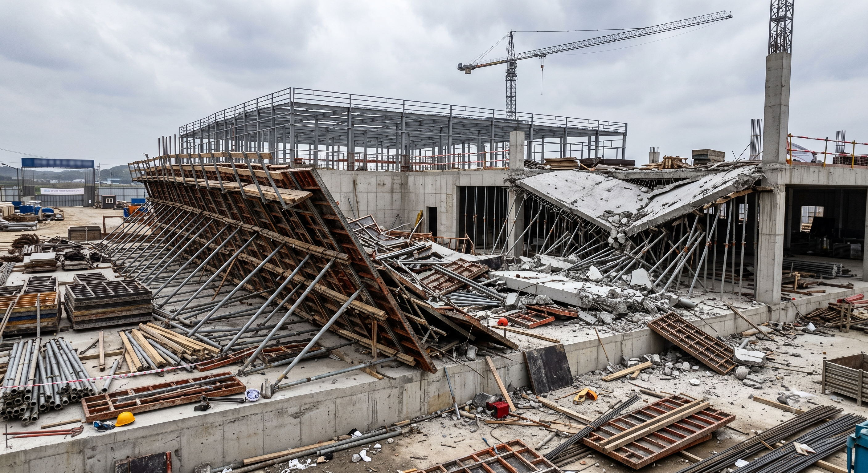
The original educational image is retained. It is not evidence of an actual incident or site suitability.
The scenario and record comparisons are fictional teaching examples, not records of real incidents, measurements, inspections, signatures or approvals.
| Item | Fictional scenario |
|---|---|
| Initial situation | Fictional example: a wall panel is held by a crane while the crew positions its braces. |
| Changed condition | The crew wants the hook released before the base anchors and braces are secured. |
| Failure path | The broad panel receives wind load without its designed independent restraint. |
| Possible outcome | It may overturn, damaging edge protection and exposing people on more than one level. |
| Prevention barrier | Keep the lifting operation controlled until the specified restraints are secured and checked; manage wind and the exclusion area throughout. |
Failure mechanisms
A wall form needs a stable load path in each erection stage, not only after both faces and ties are complete. Panel weight and friction at the base do not demonstrate resistance to wind, impact or erection loads. The lifting arrangement is not a substitute for the designed permanent temporary restraint before release.
Fresh concrete pressure depends on the design assumptions, including placement rate, temperature, mix and vibration. Self-compacting concrete or a mix change can invalidate the assumed pressure. A simple hydrostatic model is not a universal pour-rate calculator, and pressure does not invariably grow exponentially. Stop and review changes before loading the forms.
Stripping changes how the slab and lower floors carry self-weight and construction loads. Surface dryness, elapsed days or a generic percentage of specified strength cannot establish capacity. Evidence must represent the concrete and loading in question and be assessed with the removal and reshoring plan.
Decision sequence
| Decision stage | What to verify |
|---|---|
| Known facts | The panel has been positioned but not independently restrained. |
| Unresolved matters | Anchor capacity, installed brace connections and the wind condition are unresolved. |
| Reason to hold | Hook release would remove the current support before the next load path is established. |
| Required evidence | Check the current drawing, installed anchors and braces, permitted wind conditions and exclusion boundary. |
| Restart decision | The designated person verifies the evidence and authorises release only within the agreed lifting and erection method. |
5. Conditional decisions and common errors
| Condition | Action | Evidence | Proceed when |
|---|---|---|---|
| Brace incomplete | Retain controlled support; secure designed restraint | Drawing, anchors and installed braces | Restraint checked |
| Mix or rate changed | Hold the pour; reassess design assumptions | Mix details, rate and pressure basis | Pour plan released |
| Movement detected | Stop loading; evacuate affected zone | Defect and stability assessment | Stability confirmed |
| Strength unresolved | Retain support; review removal and reshoring | Strength evidence and load assessment | Removal released |
Similar situations, different decisions
The scenario and record comparisons are fictional teaching examples, not records of real incidents, measurements, inspections, signatures or approvals.
| Comparison | Situation A | Situation B |
|---|---|---|
| Erection | Panel upright with crane support: restraint still unresolved | Independent braces checked: hook release can be considered |
| Concrete | Specified mix and planned rate: monitor the agreed limits | Changed mix, temperature or rate: design review before continuing |
| Removal | Representatively verified strength plus a compatible load plan | Dry surface or elapsed days alone: retain support and investigate |
6. Roles and responsibilities
| Role | Responsibility |
|---|---|
| Work supervisor | Design basis → delivery → restraint → pre-pour inspection → placement → strength and reshoring → controlled removal |
| Technical reviewer | Current drawings, component compatibility, load paths, base support, anchors, ties and erection stages. For Ontario systems within section 89(1), the design and pre-pour inspection requirements of section 89 apply, including the written inspection statement and retention of drawings. Reshoring is separately designed under section 90. Section 88 addresses adequate concrete capacity or adequate reshoring. The original national 75% threshold, 1:500 tolerance and fixed bracing angle were unsupported and are not retained. |
| Work crew | Mix, temperature, consistency, admixtures, placement rate, vibration and construction loads used in the design. |
| Inspector / assessor | Competent personnel, pre-pour checks, safe observation positions, stop signals and defect resolution. |
| Release / handover authority | Specified strength evidence, loads above and below, removal order, reshoring and written release arrangements. |
Supervision, records, handover
| Job stage | Technical and procedural controls | Site verification |
|---|---|---|
| Scope and authority | 1. Issue current design2. Assign load control3. Coordinate trades | 1. Drawing revision2. Load owner3. Work boundaries |
| Erection release | 1. Record restraint check2. Agree lift signals3. Name release authority | 1. Anchors and braces2. Lift communication3. Release record |
| Pour readiness | 1. Close inspection items2. Record defect actions3. Confirm mix and rate | 1. Pre-pour statement2. Defect closure3. Pour parameters |
| Watch and stop | 1. Set protected position2. Test stop signal3. Record changes | 1. Observer location2. Stop arrangements3. Change record |
| Stripping decision | 1. Link element evidence2. Review actual loads3. Release removal plan | 1. Strength reference2. Load review3. Reshore plan |
| Handover | 1. Mark retained supports2. Quarantine defects3. Hand over load limits | 1. Remaining supports2. Open defects3. Receiving person |
7. Hold points and record comparison
| Hold point | Evidence before release | Confirmation / approval |
|---|---|---|
| Start | Delivery, wall and column form erection, slab falsework and decking, concrete placement surveillance, stripping, reshoring and material recovery for conventional cast-in-place work. | |
| HP-1 Delivery and storage | Lift plan · Gear condition · Stack support · Storage position | |
| HP-2 Wall form erection | Brace connections · Anchor evidence · Release check · Access protection | |
| HP-3 Pre-pour release | Inspection record · Tie arrangement · Pour parameters · Open defects | |
| HP-4 Strip and reshore | Strength evidence · Load assessment · Reshore arrangement · Exclusion zone |
Complete after actual checks. Recheck after changes, defects or shift handover.
Record comparison examples
The scenario and record comparisons are fictional teaching examples, not records of real incidents, measurements, inspections, signatures or approvals.
The boxes are static record prompts, not interactive or saved approvals. A tick does not establish suitability or permission to restart. Record the evidence, person, time and unresolved issues; retain the change history.
| Record type | Insufficient record | Record checklist |
|---|---|---|
| Restraint | Panel looks stable | □ Drawing revision□ Anchor evidence□ Brace connections□ Release authority |
| Placement | Pour checked | □ Mix and rate□ Observation position□ Movement/defects□ Stop and restart record |
| Strength | Concrete hard | □ Element and date□ Test/evidence reference□ Required capacity□ Removal decision |
| Handover | Area finished | □ Remaining reshores□ Permitted loads□ Open defects□ Receiving person |
8. Site checklist and emergency response
| Check item | Result | Person / action |
|---|---|---|
| □ Design and method: Drawing revision | ||
| □ Delivery and storage: Lift plan | ||
| □ Wall form erection: Brace connections | ||
| □ Falsework and deck: Bases and heads | ||
| □ Pre-pour release: Inspection record | ||
| □ Placement watch: Rate and sequence | ||
| □ Strip and reshore: Strength evidence | ||
| □ Recover and hand over: Clear access | ||
| □ Release / handover authority |
Stop work
Stop placing or moving materials when braces, ties or shores move, the base settles, the planned rate is exceeded, an exclusion zone is entered or the approved configuration changes. Withdraw from the potential collapse area; do not send a person below unstable falsework to tighten it under load.
Emergency response
Stop concrete supply from a safe position, evacuate the affected area and adjacent load paths, and call site emergency responders. Do not enter a collapse zone for improvised recovery. A competent technical review must establish stability and the recovery method before anyone approaches or loading resumes.
9. Sources and review limits
2026-10-05
| Source | Scope and limitations |
|---|---|
| Ontario O. Reg. 213/91, ss. 87–92 | Ontario construction requirements only. Section 89 has specified system triggers; sections 88 and 90 address removal and engineered reshoring. Check the actual jurisdiction before use. |
This is reference content written and revised with AI. It has not been verified or approved by a professional. Review by a suitably qualified professional and site authorisation are required before use.
10. PDF guidance and FAQ
PDF A covers basic task controls; B focuses on technical failures; C covers supervision, records and handover. The article has eight stages with four items per main cell; each PDF has six key stages with three items per main cell. P/S/R/A, measurements, confirmations and signatures remain blank for actual site assessment.
Content group ID
jsa-form-work
Is bracing at 2 m a universal rule?
No. The approved system and design determine the spacing, connections and permissible extension. A repeated spacing in a template is not a design.
Does 75% concrete strength permit stripping?
No universal percentage is provided here. The concrete must meet the applicable removal criteria for actual self-weight, imposed loads and reshoring arrangements.
Should the form watcher stand beneath the pour?
Observation must be planned from a protected position with a way to stop supply. Do not place a watcher inside a potential collapse or falling-material zone.
Are nets and harnesses interchangeable with guardrails?
No. Select collective protection first where practicable, then assess residual exposure, suitable anchors, clearance and rescue. A debris net is not automatically a person-catching safety net.
Has a professional verified or approved this document?
No. Public sources and editorial, layout and consistency checks were reviewed using AI. No site inspection or professional technical approval has been performed. Obtain appropriate professional review before use.
11. Revision history and authorship
This is reference content written and revised with AI. It has not been verified or approved by a professional. Review by a suitably qualified professional and site authorisation are required before use.
| Date | Version | Change | Review status |
|---|---|---|---|
| 2026-09-13 | Original version unmarked | Original preserved | No professional approval |
| 2026-10-05 | 1.1 | Decisions, records, JSA and PDFs revised | No professional approval |
Unverified incident locations, injuries and regulator investigations were replaced with an explicitly fictional scenario. Generic 2 m bracing, fixed setbacks, automatic 100% tie-off, exponential-pressure claims and claims that the platform calculates or guarantees compliant engineering parameters were removed. Valid controls for lifting, immediate restraint, planned placement, strength assessment, controlled stripping and housekeeping were retained.