This is reference content written and revised with AI. It has not been verified or approved by a professional. Review by a suitably qualified professional and site authorisation are required before use.
Revision: the master JSA is organised into eight stages with four prompts in each main cell. Short conditional release criteria and sixteen record prompts separate evidence from approval. Three six-stage PDFs use task, technical-failure and supervision viewpoints; actual evaluation fields remain blank. Valid prior explanations, sources and history are retained. This is an editorial revision, not professional technical verification.
1. Legal and technical scope
Review update, 12 October 2026: the entries below identify the official material rechecked for this revision and its specific scope. Earlier source notes and dates are retained as revision history; they do not mean that every cited provision was reverified today. Full paid standards, actual equipment manuals, site calculations and approvals were not supplied or verified. Resolve their current applicability with a qualified reviewer before use.
| Source | Scope and limitations |
|---|---|
| WorkSafeBC — Part 20 | Sections 20.78–20.83 concern qualified professional/engineering instructions and staged excavation protection. Assess water, vibration, structures and actual conditions; nominal depth alone does not establish a suitable support arrangement. |
A. British Columbia jurisdiction
This guide addresses installation of engineered steel walers, brackets, struts and associated bracing for excavation support at construction workplaces under WorkSafeBC jurisdiction in British Columbia, Canada. “H-beam shoring” is used as a practical search term; actual member sections and connection details are project-specific.
• The Workers Compensation Act and BC Occupational Health and Safety Regulation provide the principal occupational safety requirements.
• Confirm jurisdiction before applying this guide to federally regulated activities, mines or other workplaces with a different regulatory framework.
• Confirm municipal excavation, street-use, utility and fire requirements for the actual location.
B. Excavation and engineering requirements
OHS Regulation section 20.78 requires certified professional instructions for specified excavations, including those deeper than 6 m, those adjacent to structures or improvements, and specified ground-movement hazards. Where those excavations use support structures, the instructions must be from a professional engineer.
• Sections 20.81 and 20.83 address protective arrangements and shoring installation.
• For the custom steel support system described here, obtain project-specific engineering instructions covering every construction stage.
• Do not treat the prescriptive trench-support tables as a design for an arbitrary deep, wide excavation.
Legal reference: WorkSafeBC OHS Regulation, Part 20
C. Falls and work access
Under section 11.2, fall protection is required where a fall of 3 m or more could occur, and at lesser heights where the injury risk exceeds that of falling onto a flat surface. Follow the hierarchy favouring guardrails or similar restraint where practicable. Section 11.3 requires a written plan where its conditions apply, including possible falls of 7.5 m or more without permanent guardrails.
• A harness alone does not provide protection: the complete system, clearance and rescue arrangements must be suitable.
• Part 13 governs work platforms. Section 13.33 includes a specific conditional exemption for scissor lifts; requirements must be checked for the actual platform.
• A MEWP is an access option, not a universal requirement for every connection.
Fall protection: Part 11
Work platforms: Part 13
D. Lifting, rigging and referenced standards
Sections 15.2 and 15.3 address qualified rigging work and safe support before unhooking. A blanket requirement for a particular “certified rigger” credential is not substituted for the actual BC wording.
• Section 15.40(2) specifies a double-wrap arrangement for qualifying multi-piece loads over 3 m long; it is not a universal instruction for every individual H-beam.
• Part 14 governs applicable cranes and hoists. Equipment type, operator requirements, load charts and certification records must be checked separately from rigging competence.
• Section 15.30 references ASME B30.9-2006 for the listed sling types, subject to the Regulation. Section 12.112 references CSA W117.2-94 for welding and allied processes. These are regulatory references, not claims that these are the newest commercially published editions.
• Generic references to CSA Z150, CSA B354 or CSA Z259 do not establish compliance with every applicable requirement. Record the actual standard, edition and basis for its application.
• CSA S269.1 is not used here as blanket authority for excavation-support design or mandatory clamps at every strut intersection. Its applicability to a particular component must be established separately.
Cranes and hoists: Part 14
Rigging: Part 15
Welding: Part 12
E. JSA and permit status
A job safety analysis, also called a job hazard analysis, organizes task hazards and controls. The high-risk work permit in this guide is a proposed site authorization process, not a universal BC shoring permit prescribed under that name.
• Separate statutory requirements still apply. For example, section 9.13 requires a confined-space entry permit in its specified circumstances.
• An excavation is not automatically a confined space solely because it is deep. Assess the actual configuration and hazards.
• A JSA, permit or favourable risk score cannot waive legislation, engineering instructions, equipment limitations, inspections or an unresolved Hold Point.
Confined spaces and entry permits: Part 9
2. Scope and required inputs
A. Work covered
This JSA covers planning, staged excavation interfaces, unloading, safe access, bracket and waler installation, strut placement, connection completion, specified hydraulic preloading, bracing, inspection and handover.
• Soldier piles, retaining panels or other primary wall elements are assumed to have been installed and accepted for the relevant stage under a separate work package.
• Pile driving, drilling, ground anchors, underwater work, demolition and shoring removal require additional task-specific assessments.
• A raker system needs its own checks for foundations, thrust blocks and reaction paths; it must not be treated as a horizontal strut system.
B. Engineering package
Before release, assemble a coordinated package identifying:
• Excavation geometry, soil profile, groundwater assumptions and nearby structures or utilities.
• Wall and member identification, material grades, support elevations, connection details and permitted tolerances.
• Excavation increments, installation sequence, temporary stability measures and restrictions on unsupported excavation.
• Crane and equipment surcharge locations, stockpile limits and any access loads carried by the shoring.
• Preload requirements, where specified, including target force, sequence, acceptable movement, lock-off and pressure-release arrangements.
• Monitoring locations, baseline readings, alert and stop thresholds, reporting intervals and response responsibilities.
• Inspection requirements, engineering field reviews and criteria for releasing the next stage.
C. Equipment and personnel records
Keep the applicable documents available to the work team:
• Lift plan, load information, rigging configuration and crane setup assessment.
• Equipment manuals, identification, inspection records and required certification.
• Access plan, fall protection plan where required, anchor information and rescue arrangements.
• Hydraulic equipment ratings and the calibration or verification records required by the specified jacking procedure.
• Welding procedures, welder qualifications where required, bolt installation method and connection inspection plan.
• Training, demonstrated competence, required licences or certificates, and employer authorization for assigned tasks.
D. Notifications and related permits
Check Notice of Project requirements before mobilization. Section 20.2 includes triggers relevant to engineered construction and excavation; where required, normal notification is at least 24 hours before work, with posting requirements and a defined emergency exception. Notification is not design approval.
• Coordinate excavation authorization, utility-owner conditions, lifting controls and hot-work authorization.
• Assess whether confined-space permits, traffic arrangements or local permits apply.
• Resolve missing design values before work. Do not replace them with generic internet values.
3. Eight-stage JSA
| Job stage | Hazards and effects | Failure factors | Technical and procedural controls | Site verification | P | S | R | A |
|---|---|---|---|---|---|---|---|---|
| 1. Plan and ground | 1. Ground collapse2. Water or base failure3. Service strike4. Adjacent settlement | 1. Wrong ground model2. Excavation too deep3. Unknown services4. Surcharge omitted | 1. Check staged design2. Verify ground and water3. Locate and protect services4. Set monitoring triggers | 1. Design and stage revision2. Ground and water record3. Service clearance4. Baseline and triggers | ||||
| 2. Lift and access | 1. Dropped steel2. Crane or platform overturns3. Fall from access4. Crushing by load | 1. Wrong mass or rigging2. Weak plant support3. Unreachable sling release4. Shared lifting zone | 1. Verify actual lift setup2. Provide checked plant base3. Plan protected access4. Exclude load movement zone | 1. Mass and rigging check2. Plant support assessment3. Access and rescue plan4. Signalling and exclusion | ||||
| 3. Seats and walers | 1. Falling bracket2. Waler rotation3. Weld burn or fire4. Wall connection failure | 1. Wrong bearing detail2. Early hook release3. Uncontrolled hot work4. Unapproved attachment | 1. Match seats to design2. Secure before hook release3. Apply hot-work controls4. Inspect required connections | 1. Seat and bearing check2. Erection release record3. Hot-work and fume controls4. Weld and bolt evidence | ||||
| 4. Place struts | 1. Strut rolls or slips2. Hand crushed at joint3. Fall from bare beam4. Temporary instability | 1. Missing erection restraint2. Hands in bolt holes3. No protected work position4. Wrong member or length | 1. Fit designed restraints2. Use alignment tools3. Keep off bare flanges4. Verify member and seating | 1. Member identification2. Restraint inspection3. Protected access check4. Load-transfer release | ||||
| 5. Connect and brace | 1. Member buckling2. Connection failure3. Dropped tools4. Welding fume exposure | 1. Brace has no load path2. Wrong bolt or weld3. Tools unsecured4. Poor source extraction | 1. Complete load-path details2. Apply connection procedure3. Secure tools and lower zone4. Control fumes at source | 1. Brace and reaction check2. Bolt and weld acceptance3. Tool and zone check4. Exposure-control evidence | ||||
| 6. Preload and lock | 1. Jack or plate ejects2. Hydraulic injection3. Support overload4. Load lost at lock-off | 1. Eccentric jack reaction2. Damaged pressure line3. Wrong force conversion4. Unverified retaining system | 1. Use engineered procedure2. Keep clear of release paths3. Monitor force and movement4. Verify retained load transfer | 1. Jack and gauge records2. Preload and movement log3. Lock-off acceptance4. Leak and pressure checks | ||||
| 7. Inspect and access | 1. Unaccepted support loaded2. Fall from walkway3. Added load overstresses strut4. Unresolved defect | 1. Inspection incomplete2. Missing edge protection3. Walkway load omitted4. Paint mark treated as proof | 1. Close stage defects2. Check walkway and guards3. Verify added loads by design4. Record acceptance evidence | 1. As-built support record2. Walkway and guard check3. Added-load approval basis4. Closed inspection issues | ||||
| 8. Handover and monitor | 1. Next excavation collapses2. Movement goes unnoticed3. Unsafe alteration4. Rescuer exposed | 1. Stage not released2. Monitoring unavailable3. Strut removed for access4. Rescue improvised | 1. Release next stage explicitly2. Maintain trigger response3. Control all support changes4. Use planned protected rescue | 1. Stage and limits handover2. Monitoring status3. Change-control record4. Emergency readiness |
PDF A covers basic task controls; B focuses on technical failures; C covers supervision, records and handover. The article has eight stages with four items per main cell; each PDF has six key stages with three items per main cell. P/S/R/A, measurements, confirmations and signatures remain blank for actual site assessment.
4. Fictional scenario and failure mechanisms
A. Simulation notice and illustration
The following case is a hypothetical simulation for training and risk assessment. It does not describe an actual accident, a government investigation or an incident involving a particular company.
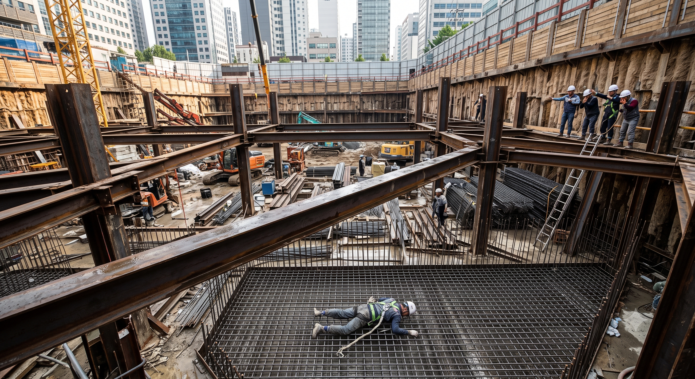
The original image is retained for discussion. Its provenance and structural accuracy have not been independently established. Do not use it as evidence of an actual accident, a fabrication detail or an approved work method.
B. Initial conditions
Consider a fictional urban excavation in British Columbia with a third level of internal steel bracing being installed above an excavation approximately 14 m deep. A crane places a strut between opposing walers. The member is resting on temporary seats, but the specified restraint and connection checks are incomplete.
• The 14 m depth is a scenario assumption, not an operating limit or an actual project measurement.
• No particular beam size, crane capacity or preload is assumed to be suitable. Those require project calculations and equipment data.
• The planned access platform cannot reach the rigging attachment without repositioning.
C. Changing weather and work conditions
Rain increases seepage and leaves the exposed steel wet. Congestion restricts the access route, and the crew feels pressure to release the crane. No documented reassessment confirms that the changed access and ground conditions remain acceptable.
• Moisture increases the likelihood of slipping.
• Water ingress may also affect the excavation, but increased structural loading cannot be quantified from this narrative.
• A delayed lift does not justify changing the access method without reassessment.
D. Plausible initiating event and consequences
A worker leaves the protected work position and attempts to cross the unsecured strut to disconnect the rigging. The worker slips and falls into the excavation, potentially suffering fatal injuries.
• The fall can occur without any structural failure of the strut.
• A loose member might also roll or shift, depending on seat geometry, restraints and load conditions. The worker's slip alone does not prove that rotation occurred or caused the fall.
• Uncontrolled movement could strike another worker, dislodge adjacent components or damage installed support.
E. Separate hydraulic failure branch
In a separate scenario, a crew begins preloading before the reaction-seat connection and required bracing are accepted. The jack is not properly aligned with its designed reaction path.
• Eccentric reaction, inadequate bearing or defective restraint could produce local damage or jack displacement.
• A hose or seal failure could cause pressure loss, fluid injection or sudden load redistribution.
• Violent member movement is possible in some configurations, but a seal failure does not automatically produce structural whipping or collapse. The actual consequences depend on stored energy, restraints and load-retention arrangements.
F. Structural and mechanical interpretation
The following relationships explain possible mechanisms. They are not design calculations or acceptance criteria.
Earth and water actions
• Use a site-specific lateral pressure distribution that accounts for soil behaviour, groundwater, surcharge, wall stiffness and construction sequence. A fully mobilized active-pressure triangle is not a universal model for a restrained, multilevel excavation.
• For a vertical face with a triangular hydrostatic pressure distribution, zero pressure at the water surface and no balancing pressure on the opposite side, the water resultant per unit wall length is:
P_w = ½ γ_w H_w²
• Here, γ_w is water unit weight and H_w is water depth. The original expression omitted the one-half factor for this particular hydrostatic resultant. Where water acts on both sides, evaluate the net pressure distribution.
• A general resultant per unit wall length may be expressed as:
P_total = integral from 0 to H of [p′h(z) + u_net(z) + p_surcharge(z)] dz
• This expression does not determine individual strut loads. Those depend on wall behaviour, support spacing and the staged structural model. Avoid double-counting surcharge or water when using an adopted pressure envelope.
Member stability
• For an ideal elastic column, Euler's relationship illustrates sensitivity to unbraced length:
N_cr = π² E I / (K L)²
• Actual resistance also depends on imperfections, local buckling, section properties, eccentricity, restraint stiffness, connection behaviour and applicable design factors.
• A compression strut may be governed by flexural or other instability modes. “Lateral-torsional buckling” is not an adequate universal description of every strut failure.
• A crossing member does not reduce effective length unless its connection and supporting load path provide the required restraint.
Preload and stored energy
• For an ideal prismatic, linearly elastic member under concentric axial load, shortening magnitude and elastic strain energy are:
ΔL = N L / (A E); U = N² L / (2 A E)
• These relationships omit joint seating, slip, wall movement and hydraulic-system compliance.
• Jack force may be estimated from pressure and effective piston area only within an appropriate equipment-specific calibration or verification method. Gauge pressure alone does not establish strut force, alignment or structural adequacy.
• The original generic 500–1,000 kN preload range is not retained as an instruction or a verified characteristic of this system.
Interpretation limits
• No site investigation, structural calculations, equipment records or forensic evidence were supplied.
• The order of failures and the governing cause remain hypotheses.
• Technical background on staged earth-pressure behaviour is available in FHWA Geotechnical Engineering Circular No. 4, Chapter 5. This is explanatory engineering literature, not BC legislation or a substitute for the project design.
G. Failed protective barriers
| Protective barrier | Hypothetical failure | Potential consequence | Required restoration before restart |
|---|---|---|---|
| Protected work access |
|
|
|
| Fall protection |
|
|
|
| Temporary stability and load transfer |
|
|
|
| Hydraulic reaction and load retention |
|
|
|
| Change control and monitoring |
|
|
|
H. Key lessons
• Resolve connection access before lifting the member.
• Separate structural stability, fall protection and lifting release checks; one does not prove the others.
• Preloading is a controlled load-transfer operation, not an improvised stability test.
• After abnormal movement, evacuate the affected area and obtain an engineered recovery plan. Do not approach the loaded assembly to adjust bolts, welds or hydraulic fittings.
5. Conditional decisions and common errors
| Condition | Action | Evidence | Proceed when |
|---|---|---|---|
| Rain or seepage changes | Hold the affected excavation; assess drainage and support response. | Water observations, movement trends and engineering disposition. | Water and support conditions accepted. |
| Rigging point unreachable | Stop unhooking; revise the protected access and lifting arrangement. | Access reach check, support assessment and lifting-team briefing. | Protected access and stable seating confirmed. |
| Unexpected preload response | Keep people clear; obtain the engineered response without uncontrolled unloading. | Force/movement log, equipment checks and revised load-transfer instruction. | Cause resolved; load retention accepted. |
| Next excavation stage | Close support defects and check monitoring before releasing the next cut. | As-built acceptance, stage drawing and current monitoring. | Required support accepted; monitoring active. |
A. Staged support and groundwater
• Identify the load path from retained ground through the wall, walers, connections and struts to the resisting support.
• Install shoring from the top down as required by section 20.83, coordinated with the engineered excavation sequence.
• Manage seepage, surface runoff and pumping under the site plan. Unplanned drawdown may affect nearby ground and structures.
• Do not assume a trench box restrains ground movement outside the excavation or supports neighbouring foundations.
B. Lifting and landing
• Select lifting points and rigging for member geometry, weight, centre of gravity and the actual hitch.
• Do not regard a generic double-choke instruction as a substitute for checking the load configuration.
• Define the support condition required before transferring load from the crane. “Keep tension until everything is welded” is not a universal sequence.
• Keep lifting and jacking operations separate unless their interaction is explicitly engineered. Do not use the crane to counteract preload or force a misaligned member into place.
C. Access and fall prevention
• Provide protected access that remains usable as the excavation and bracing geometry change.
• Treat walkways attached to shoring as additional structural loads requiring design consideration.
• Check that a fall protection anchorage is suitable for the actual construction stage. An unfinished strut is not an assumed anchor.
• For MEWPs, verify ground support, reach, entrapment exposure and the manufacturer's operating limitations.
D. Connections and cross-bracing
• Specify the bolt grade, assembly, installation method and inspection criteria for each connection. Torque is not a universal proxy for bolt tension.
• Use paint marks only as supplementary identification or movement indicators. They do not establish bolt pretension or connection capacity.
• Do not add U-bolts, welds, stiffeners, holes or clamps without confirming the design detail and material suitability.
• Complete the restraints needed for each stage before imposing the corresponding load.
E. Hydraulic preloading
• Use preload only where the engineered procedure calls for it. Record both the target and its basis.
• Confirm jack capacity, effective area, stroke limits, bearing alignment, hose compatibility and the specified force-verification method.
• Define the exclusion area from credible jack, member and hose movement. A narrow zone along the jack axis may be inadequate.
• Establish stop criteria for unexplained pressure change, load loss, excessive stroke, leakage, seat movement and monitoring exceedance.
• Do not tighten a leaking fitting under pressure, inspect a leak with a hand, improvise packing or modify relief settings.
• Transfer load and release pressure only through the approved sequence. Use the designed retention arrangement; do not assume every system has the same lock nut, pin or mechanical lock.
F. Welding, exposure and fire
• Identify the base metal, consumables and coatings before assessing exposure. Manganese, chromium compounds, zinc oxide and other contaminants depend on the materials and process; they are not identical in every weld.
• Provide effective local exhaust at fixed welding workstations as required by section 12.114. Assess other welding locations for effective exposure control.
• Select respiratory protection through the required programme. A P100 particulate filter does not supply oxygen or, by itself, remove hazardous gases and vapours.
• Use hot-work authorization to document combustible-material protection, suitable extinguishers, surveillance and final inspection responsibilities.
• Determine the fire-watch duration and inspection arrangement from the applicable fire code, referenced requirements and site conditions. Do not use the original “30–60 minutes” statement as a verified BC rule.
• The National Fire Code 2020, Division B, Article 5.2.3.1 contains conditional fire-watch and final-inspection provisions. Confirm the BC adoption amendments and any local requirements before incorporating its numerical provisions into a site permit.
Respiratory protection requirements: Part 8
BC Fire Code adoption information
National Fire Code 2020, Division B, Section 5.2
G. Operating limits and stop-work decisions
• Record wind, visibility, precipitation and other relevant limits from the actual crane, MEWP, lift plan and engineering instructions. No universal wind limit is assigned here.
• Where compatible limits govern the same operation, remain within the most restrictive applicable condition. Resolve contradictory requirements before work.
• Stop and reassess following unexpected ground movement, significant water changes, plant impact, loss of monitoring, equipment defects or altered access.
• A permit issuer cannot authorize exceeding an equipment limit or bypassing an engineering Hold Point.
6. Roles and responsibilities
A. Owner and prime contractor
Provide relevant site information and coordinate interacting employers, access, emergency arrangements and work sequencing within their respective duties. Confirm who controls excavation release and restrictions affecting other trades.
B. Employer and site supervisor
Provide competent personnel, suitable equipment and effective procedures. Brief the crew, confirm field conditions, maintain the permit system and stop work when the approved conditions are not met.
C. Responsible professional engineer
Use an engineer authorized to practise in BC and competent in the relevant work. Define the engineering scope, construction stages, connection criteria, monitoring limits and required field reviews. A review of one detail does not imply acceptance of the entire excavation.
D. Lifting and installation team
The crane operator, rigging personnel, signaller, connectors and access-equipment operators must understand their assigned tasks and communication arrangements. The person authorized to release rigging must be identified before the lift.
E. Specialist reviewers and emergency personnel
Assign connection inspection, welding inspection, exposure assessment, survey monitoring, fire watch and rescue responsibilities according to the project needs. Record competence and the limits of each assignment.
F. Qualification distinctions
• Training attendance does not by itself demonstrate competence.
• Employer authorization does not replace a required licence, certificate or professional registration.
• Professional registration does not automatically establish competence in every discipline.
• Medical suitability, including assessment for respirator use where required, is separate from task authorization.
Workers Compensation Act, Part 2, sections 21–25
Supervision, records, handover
| Job stage | Technical and procedural controls | Site verification |
|---|---|---|
| Plan ownership | 1. Verify assigned authority2. Check staged design3. Set monitoring triggers | 1. Design and stage revision2. Ground and water record3. Service clearance |
| Team and equipment | 1. Record equipment evidence2. Verify actual lift setup3. Exclude load movement zone | 1. Mass and rigging check2. Plant support assessment3. Access and rescue plan |
| Stage release | 1. Hold stage release2. Fit designed restraints3. Verify member and seating | 1. Member identification2. Restraint inspection3. Protected access check |
| Energy control | 1. Record energy controls2. Use engineered procedure3. Verify retained load transfer | 1. Jack and gauge records2. Preload and movement log3. Lock-off acceptance |
| Inspection closure | 1. Close inspection defects2. Close stage defects3. Record acceptance evidence | 1. As-built support record2. Walkway and guard check3. Added-load approval basis |
| Shift handover | 1. Transmit limits and issues2. Release next stage explicitly3. Use planned protected rescue | 1. Stage and limits handover2. Monitoring status3. Change-control record |
7. Hold points and record comparison
A. Permit content
Record the site, excavation zone, support level, drawing revision, authorized activities, responsible persons, validity period, linked permits and conditions requiring suspension. Each release needs the applicable evidence, the authorized person's name, and the date and time.
B. Proposed release schedule
These Hold Points are proposed project controls. Assign the final signatories in the engineering and site-management plans.
| Hold Point | Release required before | Evidence required | Proposed release responsibility |
|---|---|---|---|
| HP1 — Engineering and coordination | Starting the installation package |
|
|
| HP2 — Ground and excavation stage | Entering the installation area or positioning plant |
|
|
| HP3 — Access and rescue | Starting elevated connection work |
|
|
| HP4 — Member support | Detaching lifting rigging |
|
|
| HP5 — Jacking readiness | Applying hydraulic preload |
|
|
| HP6 — Load retention | Removing jacks or releasing temporary load support |
|
|
| HP7 — Stage completion | Further excavation or new loading |
|
|
| HP8 — Change or restart | Resuming after a material change or stop event |
|
|
C. Related permit gates
• Authorize hot work before welding or cutting begins, including during bracket installation.
• Complete a statutory confined-space entry permit when applicable; the general shoring permit does not replace it.
• Suspend the affected authorization if the drawing revision, support condition, access method, equipment or environmental conditions change materially.
• A verbal assurance or a low risk score does not release a Hold Point.
Record comparison examples
The scenario and record comparisons are fictional teaching examples, not records of real incidents, measurements, inspections, signatures or approvals.
The boxes are static record prompts, not interactive or saved approvals. A tick does not establish suitability or permission to restart. Record the evidence, person, time and unresolved issues; retain the change history.
| Record type | Insufficient record | Record checklist |
|---|---|---|
| Plan and ground | “OK” | □ Design and stage revision□ Ground and water record□ Service clearance□ Baseline and triggers |
| Place struts | “OK” | □ Member identification□ Restraint inspection□ Protected access check□ Load-transfer release |
| Preload and lock | “OK” | □ Jack and gauge records□ Preload and movement log□ Lock-off acceptance□ Leak and pressure checks |
| Handover and monitor | “OK” | □ Stage and limits handover□ Monitoring status□ Change-control record□ Emergency readiness |
8. Site checklist and emergency response
A. Documents and people
• ☐ Current drawings and stage-specific instructions are available and understood.
• ☐ Required notices and linked permits are in place.
• ☐ Roles, communication signals and release authorities are assigned.
• ☐ Training, task competence and required credentials have been checked.
B. Ground, wall and monitoring
• ☐ The exposed ground and wall condition match the permitted stage.
• ☐ Utility controls and adjacent-structure restrictions are confirmed.
• ☐ Groundwater, drainage and monitoring readings are acceptable.
• ☐ Plant positions and stored materials comply with the assessed loading arrangement.
C. Steel, lifting and connections
• ☐ Member IDs, material condition and connection components match the drawings.
• ☐ Lifting weight, configuration, rigging and receiving supports are verified.
• ☐ The load path and exclusion areas are clear.
• ☐ The rigging-release criteria are understood.
D. Access, falls and emergency readiness
• ☐ Each connection can be reached from the planned protected work position.
• ☐ Fall protection and anchor arrangements suit the actual stage.
• ☐ Rescue access, equipment and communication are available.
• ☐ No one is using unsecured steel as a walkway.
E. Hot work and hydraulic operations
• ☐ Required hot-work, exposure and fire controls are ready.
• ☐ Respirators, where needed, are selected and used through the applicable programme.
• ☐ Jacking targets, equipment records, retention method and stop criteria are confirmed.
• ☐ Required preloading connections and bracing are accepted.
F. Final release
• ☐ Applicable Hold Points are signed by the assigned authorities.
• ☐ Outstanding defects are closed or the affected work remains on hold.
• ☐ Weather, ground conditions and simultaneous operations remain within the approved conditions.
• ☐ The crew knows when to stop, where to withdraw and whom to contact.
An unchecked critical item means the affected operation remains on hold. Completing this checklist does not establish structural capacity.
9. Sources and review limits
Review update, 12 October 2026: the entries below identify the official material rechecked for this revision and its specific scope. Earlier source notes and dates are retained as revision history; they do not mean that every cited provision was reverified today. Full paid standards, actual equipment manuals, site calculations and approvals were not supplied or verified. Resolve their current applicability with a qualified reviewer before use.
| Source | Scope and limitations |
|---|---|
| WorkSafeBC — Part 20 | Sections 20.78–20.83 concern qualified professional/engineering instructions and staged excavation protection. Assess water, vibration, structures and actual conditions; nominal depth alone does not establish a suitable support arrangement. |
A. Legislation and regulator sources
• BC Laws — Occupational Health and Safety Regulation, B.C. Reg. 296/97
• WorkSafeBC — Workers Compensation Act, Part 2
• WorkSafeBC — Part 20, Construction, Excavation and Demolition
• WorkSafeBC — Guidelines Part 20, including G20.78 and G20.81
• WorkSafeBC — Part 11, Fall Protection
• WorkSafeBC — Part 13, Ladders, Scaffolds and Temporary Work Platforms
• WorkSafeBC — Part 14, Cranes and Hoists
• WorkSafeBC — Part 15, Rigging
• WorkSafeBC — Part 12, including Welding, Cutting and Allied Processes
• WorkSafeBC — Part 8, Personal Protective Clothing and Equipment
• WorkSafeBC — Part 9, Confined Spaces
• Province of British Columbia — BC Fire Code
B. Application priority
• Meet applicable legislation, enforceable orders and legally incorporated requirements.
• Implement the certified engineering instructions and equipment-specific requirements that apply to the work.
• Apply contractual or project standards where specified, without reducing statutory protection.
• Use regulator guidelines to understand application; distinguish guidance from the legislative text.
• Resolve conflicting instructions through the appropriate authority before work. A site permit cannot resolve a technical conflict by selecting a convenient value.
C. Editions, amendments and verification limits
• A standard's newest publication date is not necessarily the edition incorporated into legislation. Record both where relevant.
• The standard references in this guide were checked against publicly accessible regulatory text. Full paid standards and all of their technical clauses were not independently reviewed.
• Project-specific steel design standards, welding acceptance standards and equipment manuals were not supplied. Their applicability and editions remain part of the engineering release.
• BC Fire Code adoption information and national hot-work provisions were reviewed. A complete project-specific check of provincial amendments, local fire requirements and permit conditions remains necessary before hot-work authorization.
• WorkSafeBC's update notice dated September 17, 2026 distinguishes current guidance from respiratory-protection amendments taking effect November 6, 2026. This draft does not treat the future wording as already effective.
• Exposure-limit updates effective September 3, 2026 were identified. Use the current substance-specific limits in the exposure assessment; this guide assigns no generic welding-fume limit.
WorkSafeBC — Regulatory and guideline updates
WorkSafeBC — Respiratory protection guidance
10. PDF guidance and FAQ
PDF A covers basic task controls; B focuses on technical failures; C covers supervision, records and handover. The article has eight stages with four items per main cell; each PDF has six key stages with three items per main cell. P/S/R/A, measurements, confirmations and signatures remain blank for actual site assessment.
The three PDF sheets are complementary extracts, not a complete work sequence. Apply all eight body stages and the applicable site procedure. PDF HP-0 to HP-4 are worksheet labels: match each to its event, evidence and responsible authority, not to the same number in a different permit or table. An omitted PDF stage is not permission to omit its controls.
A. Proposed project data
The following fields are proposed for a Smart JSA Bridge workflow. Their availability, validation logic and automation have not been verified in the platform.
• Country: Canada; province: British Columbia; jurisdiction code: CA-BC; language: en-CA.
• Project, excavation zone, support level, work dates and responsible employer.
• Drawing references, revisions, engineering scope and designated reviewers.
• Member, connection, crane, rigging, platform and hydraulic-equipment identifiers.
B. Proposed technical inputs
• Installation sequence and permitted excavation stage.
• Design-based preload targets, tolerances and load-retention method, where applicable.
• Monitoring baseline, alert limits, stop limits and notification responsibilities.
• Lifting configuration, access method and applicable equipment limits.
• Connection inspections, hot-work controls, respiratory-protection assessment and rescue arrangements.
C. Proposed authorization records
• JSA revision and crew briefing record.
• Linked permit references, validity and suspension conditions.
• Hold Point evidence, reviewer identity, release time and unresolved actions.
• Actual field risk assessment and acceptance decisions, entered by authorized personnel.
D. Proposed blocking rules
If implemented and validated, the workflow could prevent an authorization request from advancing when:
• A required drawing revision or inspection record is missing.
• Required pre-jacking connections or monitoring inputs are unaccepted.
• A linked permit has expired or changed conditions require reassessment.
• A recorded value exceeds an approved limit.
• Required engineering review or Hold Point release is absent.
E. Limits of automation
Software can organize records and highlight incomplete fields. It cannot observe hidden defects, establish ground stability or infer that uploaded documents are authentic and technically adequate. Automated checks must not create an engineering approval or release a Hold Point without the required authorized review.
Which rules apply to H-beam excavation shoring in British Columbia?
For work under WorkSafeBC jurisdiction, use the Workers Compensation Act and applicable parts of the BC Occupational Health and Safety Regulation, especially Part 20. The engineered excavation and support arrangements must meet the requirements applicable to the site and construction stage.
Can a JSA or high-risk work permit replace an engineered shoring design?
No. A JSA records task hazards and controls, and a site work permit coordinates authorization. Neither replaces required engineering instructions, inspections, equipment limits or unresolved hold points. Separate statutory permits may also apply.
Must every H-beam be lifted with a double-wrap choke hitch?
No universal rule applies to every individual beam. Select rigging for the actual load, geometry and working load limits. BC OHS Regulation section 15.40(2) contains a specific double-wrap requirement for qualifying loads consisting of two or more pieces of material over 3 metres long.
Is a mobile elevating work platform mandatory for every shoring connection?
Select safe access for the task, using a suitable work platform, scaffold or other compliant arrangement. A MEWP is one option, not a universal requirement. Do not use unsecured struts as walkways, and meet the applicable fall protection requirements.
What determines hydraulic strut preload and permission to continue excavation?
Use the project engineer's specified sequence, load targets, tolerances and acceptance criteria together with the equipment manufacturer's limits. Record load-transfer and monitoring results. Further excavation remains on hold until the designated reviewers release the relevant stage.
Has a professional verified or approved this document?
No. Public sources and editorial, layout and consistency checks were reviewed using AI. No site inspection or professional technical approval has been performed. Obtain appropriate professional review before use.
11. Revision history and authorship
A. Document status
This document is an automatically generated technical draft prepared within the Smart JSA Bridge engineering-content workflow. It is intended for editorial publication and subsequent project-specific review. Publication does not authorize field work.
B. No implied professional approval
No verifiable signed engineering review, manufacturer acceptance, safety-professional approval or government approval record was supplied for this document. It must not be described as having been prepared, reviewed, certified or approved by those parties.
C. No physical inspection
The system has not physically inspected the excavation, ground, structures, steel members, connections, lifting equipment, hydraulic equipment or actual work conditions. Descriptions, images and uploaded records cannot establish their condition or suitability.
D. Documents this draft does not replace
This draft is not a substitute for legal advice, manufacturer procedures, engineering calculations, required inspection reports, qualification records, a site risk assessment or work authorization. Illustrative equations and proposed controls are not approved construction instructions.
E. Review before actual use
Before field use, appropriately qualified and authorized persons must adapt and review the document for the BC workplace, actual equipment and current conditions. Missing engineering values, unresolved jurisdiction questions and unreleased Hold Points must be addressed before the affected work starts.
F. Actual professional review record
Any review actually performed must be recorded separately with:
• Reviewer name and organization.
• Qualifications and formal assignment of authority.
• Review scope.
• Equipment and documents reviewed.
• Review date and signature.
• Limitations and exclusions.
• Required revisions.
• Conditions under which approval remains valid.
G. Source-check date and revalidation
Legal and source verification date: 19 September 2026.
Recheck legislation, commencement dates, applicable transitional provisions, referenced standards and project requirements before use. Review this document again when the respiratory-protection amendments scheduled for 6 November 2026 take effect, or earlier if the work scope, equipment, design or site conditions change.
2026-10-12 · v2026.10.12
Revision: the master JSA is organised into eight stages with four prompts in each main cell. Short conditional release criteria and sixteen record prompts separate evidence from approval. Three six-stage PDFs use task, technical-failure and supervision viewpoints; actual evaluation fields remain blank. Valid prior explanations, sources and history are retained. This is an editorial revision, not professional technical verification.
This is reference content written and revised with AI. It has not been verified or approved by a professional. Review by a suitably qualified professional and site authorisation are required before use.